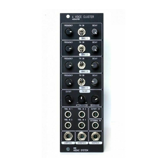
Summary of Contents for ADDAC System ADDAC105
- Page 2 ADDAC105 Assembly Guide March.2020 ADDAC SYSTEM page 2...
- Page 3 ADDAC105 Assembly Guide STEP 1: Start by locating all 6 10uF capacitors and solder them like shown below, notice the orientation on the pcb. Tip: soldering these caps is easy, just place a dab of solder on the pad on your right (left pad if you’re left handed) and then, with the help of a tweezer, put the capacitor in place and reflow the previously tinned pad to reflow the solder while pushing the capacitor down.
- Page 4 ADDAC105 Assembly Guide STEP 2: Next proceed to locate the male and female pinheaders and solder them like shown below. ADDAC SYSTEM page 4...
- Page 5 ADDAC105 Assembly Guide STEP 3: Next locate the 2x5 power header and solder it like shown below. STEP 4: Next locate a screw and the metal spacer and place attach them like shown below. ADDAC SYSTEM page 5...
- Page 6 ADDAC105 Assembly Guide STEP 5: Next locate all trim pots and flatten out their legs with the help of some pliers, like shown below. Notice there are 2 pot values: 2x B103 and 9x B104. Also notice that one of the B103 has a mid stop point.
- Page 7 ADDAC105 Assembly Guide STEP 6: Next locate and place all the front panel parts, notice the 2 different pot placement. B103 B103 Middle Stop B104 B103 B103 - Middle Stop ADDAC SYSTEM page 7...
- Page 8 ADDAC105 Assembly Guide STEP 7: After all parts are in place, fit the frontpanel in and tighten all the nuts. Proceed by soldering all pads in the back. ADDAC SYSTEM page 8...
- Page 9 ADDAC105 Assembly Guide STEP 8: Next locate and solder the 90 degree 3 pin header like shown below. STEP 9: Next locate and solder the loose wire flush to the pcb like shown below. ADDAC SYSTEM page 9...
- Page 10 ADDAC105 Assembly Guide STEP 10: Next attach the back pcb in place and solder the other end of the loose wire to the back pcb. STEP 11: Next attach the back screw. ADDAC SYSTEM page 10...
- Page 11 ADDAC105 Assembly Guide You’re done! Happy Patching! ADDAC SYSTEM page 11...
-
Page 12: Assembly Guide
For feedback, comments or problems please contact us at: addac@addacsystem.com ADDAC105 ASSEMBLY GUIDE Revision.01 March.2020...


Need help?
Do you have a question about the ADDAC105 and is the answer not in the manual?
Questions and answers