Advertisement
Quick Links
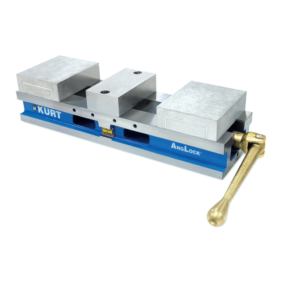
Remove, repair, and reassemble the nut and screw assembly in your HDL
series double lock vise.
In these instructions when we refer to the "front" of the vise or nut/screw
assembly, we mean the end that has the hex for the handle and is closest to
the operator. The end that is farthest from the operator is considered the
"rear".
(Numbers in parentheses reference the mechanical drawing on the last page.)
Removing the nut and screw assembly from your vise
1. Remove the rear moveable jaw from your vise.
2. Remove the button head cap screw (#28) from the front end of the
vise body.
3. Place a spacer block between the stationary jaw and the front
moveable of the vise. Place your handle on the hex end of the lead
screw (#7) and turn clockwise to draw the jaws together. As the front
jaw tightens on the block, continue turning. This will push the holding
block (#17) out of the vises center channel
load block (#34) and steel wedge friction clamp (#33) will fall out of
the holding block (#17) when it is clear of the vise.
4. Once the holding block (#17) is free of the vise remove your spacer
block, the remaining moveable jaw, and the stationary jaw.
5. Remove the chip guards (#46 & 47)
6. Slide the nut and screw assembly toward you until it is all the way out
of the vise body.
HDL(M)6 Nut/Screw Assembly
A small rubber spring pre-
.
Advertisement

Related Manuals for Kurt HDL6


Summary of Contents for Kurt HDL6
- Page 1 HDL(M)6 Nut/Screw Assembly Remove, repair, and reassemble the nut and screw assembly in your HDL series double lock vise. In these instructions when we refer to the “front” of the vise or nut/screw assembly, we mean the end that has the hex for the handle and is closest to the operator.
- Page 2 Disassembling the nut and screw assembly 1. Remove the small spiral retaining ring (#6) from the rear nut. This ring has a small tab on the end of it that can be hooked and pried inward then lifted up until it is out of the snap ring groove. 2.
- Page 3 6. Place the clutch (#13) in a vise with non marring jaws or wrap a rag around the clutch to prevent the clutch from being damaged. Apply only enough pressure to prevent the clutch from turning when you turn the lead screw using the hex handle. Do not apply so much pressure that you crush or oblong the clutch.
- Page 4 Disassembling the holding block 1. Remove set screw (#25) and set aside 2. Using a spanner wrench turn the threaded collar (#23) counter clockwise and remove it from the holding block. 3. Turn the holding block upside down and gently tap it until remaining items slide out of holding block.
- Page 5 5. Place the threaded collar (#23) on top and compress the springs while threading the collar into the holding block. The threaded collar has two holes for the spanner wrench and two half moon slots ¾ of the way down the side making an intermittent thread. Looking through the tapped hole where the set screw was (#25), continue to screw the collar into the holding block until you can see one of the slots appear.
- Page 6 6. Place three springs (#11) into the slot standing them up vertically, one spring in each hole 7. Lay the pin (#12) on top of the 3 springs holding them in place with your hand. Use a pliers to compress and hold down the pin while you slide the clutch over the top of the pin.
- Page 7 12. Stand the screw on a soft surface with the threaded end down. Use a small screw driver to push the o-ring (#15) down into the recess of the nut. 13. Slide the spiral retaining ring down using a small screw Driver.
- Page 8 20. Slide the spiral retaining ring down and thread it into the retaining ring groove of the nut in the same manner as you did in step 12 for the front nut. 21. Turn the rear nut counter clock wise until you can feel resistance. Do not force the nut any further than the point you feel resistance or it will force the seal and retainer out of place.
- Page 9 Continue to close the jaws of the vise until both the front and rear moveable contact the stationary. Replace the button head cap screw (#28) 31.Your vise is now ready for use.
Need help?
Do you have a question about the HDL6 and is the answer not in the manual?
Questions and answers