Table of Contents
Advertisement
Quick Links
Advertisement
Table of Contents

Related Manuals for Kurt HDL6


Summary of Contents for Kurt HDL6
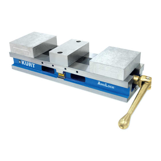
- Page 1 HDL6 MANUAL ASSEMBLY Operating Instruction Manual HDL6 (English) & HDLM6 (Metric)
-
Page 2: Table Of Contents
TABLE OF CONTENTS Introduction ...................... 3 Setup Instructions ................... 4 Vise Installation Instructions ................ 5 Operating Instructions ................6-14 HDL6 Parts List ....................15 HDL6 Mechanical Drawing ................16 Maintenance Schedule ................17-18 Troubleshooting Tips ..................19 Maintenance Log/Notes ................20 Warranty ......................21 VISE DATA Use this to fill out information about your vise for quick reference. -
Page 3: Introduction
INTRODUCTION Thank you for purchasing a Kurt HDL6 vise. You have just purchased one of the best machine vises in the industry. The outstanding accuracy of this product is second to none. Backed by a lifetime warranty against workmanship and material defects, this product is built to last when used and maintained properly. -
Page 4: Setup Instructions
SET-UP INSTRUCTIONS Now that you have your new Kurt Vise, it’s time to set-up and begin using it. You will see that your new vise comes with a Kurt swivel handle. The handle is specifically designed to provide maximum torque to your vise (clamping force provided below). -
Page 5: Vise Installation Instructions
VISE INSTALLATION INSTRUCTIONS Do not attempt to lift the vise by attaching to any of the jaws or injury may result. Always attach lifting CAUTION devise to the vise base frame. 1. Position vise on your machine table, pallet or tombstone using the .625 or 16 MM (.6299”) locating holes found on the bottom of the vise. -
Page 6: Operating Instructions
One-Sided Clamping: To properly clamp a part in your Kurt double-station vise, you should place the parts in the center of the jaws resting on the ways of the vise. - Page 7 Fig.2 Sketch #2A Incorrect part clamping. Vise width centerline Sketch #2B Correct part clamping Sketch #2C Correct part clamping Sketch #2D Correct part clamping Dummy spacer OPERATING INSTRUCTIONS...
- Page 8 OPERATING INSTRUCTIONS Clamping with Different Sized Parts: If clamping parts of different sizes, place the smaller part in the front station and the larger part in the back station as shown in Fig. 3 below. Fig.3 Back Station: Larger Part Front Station: Smaller Part...
- Page 9 Converting to a Single Station Vise: If desiring to convert your double station vise to a single station, you will TOOL NAME KURT need to get a Kurt conversion kit through our website, kurtworkholding. TOLERANCES UNLESS NOTED INCHES TITLE DECIMAL ±...
- Page 10 Standard J-Style Hard Jaws: The standard J-style hard jaws are made of ductile iron and are paired with Kurt standard jaw plates. For dimensional information and jaw positioning, see Fig. 7 and Fig. 8 on pages 11-12. Aluminum Carvable/Machinable Jaws: The Aluminum Carvable jaws come in two different jaw heights - 1.728”...
- Page 11 JAW POSITIONING Fig.7 Note: Dimensions below are in inches unless specified. 4.00 4.00 4.00 8.72 8.72 8.72 5.96 5.96 5.96 DD 10.69 DD 10.69 10.69 Q:\ENGINEERING\ENGINEERS FILES\LEVI T\RENDERING PROJECTS\REFERENCE MODELS\ OPERATING INSTRUCTIONS...
- Page 12 SIDE & END VIEW Fig.4 Note: Dimensions below are in inches unless specified. 3.125 P [TYP] 6.000 21.00 2.690 10.187 1.450 1.485 4.00 1.735 0.725 3.875 1/2 -13 1.300 3.300 4.00 OPERATING INSTRUCTIONS...
- Page 13 MOUNTING LOCATIONS Fig.9 Note: Dimensions below are in inches unless specified. 1.45 1.000 25 mm 75 mm 3.19 5.000 7.000 175 mm 2.000 50 mm M12 SHCS 1/2 SHCS 0.625 (5/8) 3.918 OPERATING INSTRUCTIONS...
- Page 14 2 per package. English Mounting: The HDL6 can be properly located using (2) of the four English sine key holes indicated by dimension QQ in Fig. 9 above. The HDL6 can be bolted down using the four English 1/2” bolt holes indicated in Fig. 9 above by dimension PP.
-
Page 15: Hdl6 Parts List
SHCS M5 X .8 X 6MM LG 26-0232 SHCS M10 X 1.5 X 45MM LG 29-0218 SBHCS M10 X 1.5 X 12 28-1122 SET SCREW, M5 X .8 X 6MM LG 04-0030 DOWEL PIN, 3/16 X .75 LG HDL6 PARTS LIST... -
Page 16: Hdl6 Mechanical Drawing
HDL(M)6 MECHANICAL DRAWING Fig.11 HDL6 MECHANICAL DRAWING... -
Page 17: Maintenance Schedule
MAINTENANCE SCHEDULE It is very important to perform regular maintenance on your Kurt vise to ensure proper operation. Improper maintenance will result in poor vise performance and may void your warranty. Daily/ Weekly 1. Remove chips from surface of vise. - Page 18 MAINTENANCE SCHEDULE 3. Place a 3.25” thick spacer in the front station, and start closing the vise and this will drive the holding block (#27 in Fig. 11) out of the vise body. 4. Once the holding block is clear of the body, reverse the screw rotation, so the spacer can be removed.
-
Page 19: Troubleshooting Tips
TROUBLESHOOTING TIPS If properly maintained, the Kurt HDL6 Series vise will operate trouble free for many years. In some cases it will be necessary to troubleshoot. Use the information below to help in the process. Problem: My vise turns hard. -
Page 20: Maintenance Log/Notes
MAINTENANCE LOG/NOTES: MAINTENANCE LOG/NOTES... -
Page 21: Warranty
The sole obligation of Kurt Manufacturing Company, Inc. (Kurt) and the purchaser’s SOLE AND EXCLUSIVE REMEDY hereunder, shall be limited to the replacement or repair of any Kurt product or part (by an authorized Kurt technician) which are returned to Kurt Manufacturing Company’s... - Page 22 If you have any feedback or questions please contact us at. Kurt Industrial Products // A Division Of Kurt Manufacturing 9445 East River Road NW | Mpls, MN 55433 Phone 763-574-8309 | Toll Free 877-226-7823 Fax 763-574-8318 | Toll Free Fax 877-226-7823 Manual Revision: kurtworkholding.com | workholding@kurt.com...
Need help?
Do you have a question about the HDL6 and is the answer not in the manual?
Questions and answers