
Related Manuals for Kurt CROSSOVER ANGLOCK VISE DX6


Summary of Contents for Kurt CROSSOVER ANGLOCK VISE DX6
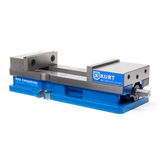
- Page 1 CROSSOVER ™ ™ ANGLOCK VISE ® BASE ASSEMBLY Operating Instruction Manual DX6/DX6R ENGLISH...
-
Page 2: Table Of Contents
TABLE OF CONTENTS Introduction ......................... 3 Setup Instructions ......................4 Operating Instructions ..................... 5-10 DX6 Parts List....................... 11 DX6 Mechanical Drawing ................... 12 DX6R Parts List......................13 DX6R Mechanical Drawing ..................14 Maintenance Schedule ..................15-17 Troubleshooting Tips ....................18 Maintenance Log/Notes .................... -
Page 3: Introduction
Introduction INTRODUCTION Thank you for purchasing a Kurt DX6 vise. You have just purchased one Thank you for purchasing a Kurt DX6 vise. You have just purchased one of the best machine vises in the industry. The outstanding accuracy of this product is second to none. Backed by a lifetime warranty, this of the best machine vises in the industry. -
Page 4: Setup Instructions
SET-UP INSTRUCTIONS Now that you have your new Kurt Vise, it’s time to set-up and begin using it. You will see that your new vise comes with a Kurt swivel handle and chip guard in the shipping carton (instruction manual available online at www.kurtworkholding.com). -
Page 5: Operating Instructions
If you need more clamping force you may require a larger vise. To properly clamp a part in your Kurt vise, you should place the part in the center of the jaws resting on the ways of the vise. Clamping only on one side or above the movable and stationary jaws can result in jaw lift or loss of accuracy. - Page 6 Fig.2 Sketch #2A Incorrect part clamping. Vise width centerline Sketch #2B Correct part clamping. Sketch #2C Correct part clamping. Sketch #2D Correct part clamping. Non- machined spacer OPERATING INSTRUCTIONS...
- Page 7 JAW POSITIONING Fig.3 Fig.3 Note: Dimensions below are in inches unless specified. OPERATING INSTRUCTIONS...
- Page 8 SIDE & END VIEW Fig.4 Note: Dimensions below are in inches unless specified. OPERATING INSTRUCTIONS...
- Page 9 MOUNTING LOCATIONS Fig.5 Note: Dimensions below are in inches unless specified. OPERATING INSTRUCTIONS...
- Page 10 SURFACE MOUNT USING SINE KEYS Mounting the new DX6 with keys requires the use of sine keys instead of standard keys. They are available in several different sizes that are listed on our website at www.kurtworkholding.com. The keys are sold in sets of 2 per package.
-
Page 11: Dx6 Parts List
3600V-8 2-piece Retaining Nut D60-9 Segment D80-41 Thrust Bearing 3600V-42 Thrust Bearing Washer WSRL46 WorkStop O-ring #117 3600V-99 Kurt Logo Label DX6-111 3600V-128 O-ring #129 3600V-147 Spiral Retaining Ring DX6-169 Wave Spring 3600V-191-SA Protective Cap Internal Brush Seal D688-211 DX6-223... -
Page 12: Dx6 Mechanical Drawing
DX6 Mechanical Drawing DX6 Mechanical Drawing Fig.7 DX6 Mechanical Drawing | ENLGISH DX6 MECHANICAL DRAWING... -
Page 13: Dx6R Parts List
3610V-8 2-Piece Retaining Nut, Reverse D60-9 Segment D80-41 Thrust Bearing 3600V-42 Thrust Bearing Washer 3600V-99 O-ring #117 DX6-111 Kurt Logo Label 3600V-128 O-ring #129 DX6-169 Wave Spring 3600V-191-SA Protective Cap WSRL46-SA Workstop Assembly (NOT SHOWN) Internal Brush Seal D688-211 DX6-223... -
Page 14: Dx6R Mechanical Drawing
DX6R Mechanical Drawing Fig.8 DX6R MECHANICAL DRAWING... -
Page 15: Maintenance Schedule
Maintenance Schedule It is very important to perform regular maintenance on your Kurt vise to ensure proper operation. Improper maintenance will result in poor vise performance and may void your warranty. Daily/ Weekly Remove chips from surface of vise. Visually inspect seals for damage and cleanliness. - Page 16 Tip the jaw so the front of the jaw (the side with the jaw plate) is on the vise bed. Lower the jaw on to the bed so that the segment contacts the hook part of the nut and rest the jaw on to the vise bed. Tighten the setscrew to firmly contact the nut.
- Page 17 3 to 6 months Open vise to maximum opening. Loosen the set-screw and remove the movable jaw. Remove spiral-retaining ring from handle end of the vise screw. Remove the screw support from the vise body. Remove the two-piece locking collar by removing the four SHCS. With one screw still half-way out spin off the first collar.
-
Page 18: Troubleshooting Tips
Troubleshooting Tips If properly maintained, The Kurt DX6 Series vise will operate trouble free for many years. In some cases, it will be necessary to troubleshoot. Use the information below to help in the process. Problem: My vise turns hard. -
Page 19: Maintenance Log/Notes
MAINTENANCE LOG/NOTES: MAINTENANCE LOG/NOTES... -
Page 20: Warranty
The sole obligation of Kurt Manufacturing Company, Inc. (Kurt) and the purchaser’s SOLE AND EXCLUSIVE REMEDY hereunder, shall be limited to the replacement or repair of any Kurt product or part (by an authorized Kurt technician) which are returned to Kurt Manufacturing Company’s place of business, transportation, shipping and postal charges prepaid,... - Page 21 Kurt Industrial Products // A Division Of Kurt Manufacturing 9445 East River Road NW | Mpls, MN 55433 | workholding@kurt.com Phone 763-574-8309 | Toll Free 877-226-7823 Fax 763-574-8318 | Toll Free Fax 877-226-7823 Manual Revision:...
Need help?
Do you have a question about the CROSSOVER ANGLOCK VISE DX6 and is the answer not in the manual?
Questions and answers