Chapters
Table of Contents

Related Manuals for HYDAC FILTER SYSTEMS MFU-15E


Summary of Contents for HYDAC FILTER SYSTEMS MFU-15E
- Page 1 MFU-15E / MFU-15S MobileFiltration Unit Operating and Maintenance Instructions English • (Translation of original instructions) Document No. : 4391552a • 8/28/2019 Follow these instructions for proper and safe use. Keep for future reference.
-
Page 2: Table Of Contents
Table of Contents HYDAC FILTER SYSTEMS GMBH Table of Contents 1 General ........................ 5 Imprint ...................... 5 Documentation Representative................ 5 Purpose of this manual .................. 6 Target group of the manual................ 6 Illustrations in the manual ................ 7 1.5.1 Illustration on the title page.............. 7 1.5.2... - Page 3 HYDAC FILTER SYSTEMS GMBH Table of Contents Technical Data .................... 28 Drawings / dimensions / hydraulic diagram............ 30 3.7.1 MFU-15E9-... Economy .............. 30 3.7.1.1 MFU-15E9 - Dimensions / hydraulic diagram ...... 31 3.7.2 MFU-15S9-... Standard .............. 34 3.7.2.1 MFU-15S9 - Dimensions / hydraulic diagram ...... 35 Operating elements on the filter unit ..............
- Page 4 Table of Contents HYDAC FILTER SYSTEMS GMBH 7 Rectifying errors ...................... 64 8 Performing maintenance .................. 67 Maintenance table.................. 68 Changing the filter element ................ 69 Removing/installing the quick coupling ............ 76 Removing/installing the protective screen............ 78 8.4.1 Removing/installing the push-in protective screen ...... 80 8.4.2...
-
Page 5: General
HYDAC FILTER SYSTEMS GMBH General | 1 1 General In this chapter, you will find helpful notes on handling these in- structions. 1.1 Imprint Manufacturer / publisher and responsible for the content: Address of the manufacturer Contact address HYDAC FILTER SYSTEMS... -
Page 6: Purpose Of This Manual
1 | General HYDAC FILTER SYSTEMS GMBH 1.3 Purpose of this manual Before you use this product for the first time or if you have been asked to carry out other work on the product, please read this manual. The use and the handling of the product described in the fol-... -
Page 7: Illustrations In The Manual
HYDAC FILTER SYSTEMS GMBH General | 1 1.5 Illustrations in the manual You will find illustrations in this manual. You can find details re- garding these in the following chapters. 1.5.1 Illustration on the title page You will find the following information on the title page of this... -
Page 8: Representation Of Requirements
1 | General HYDAC FILTER SYSTEMS GMBH The document no. with the index (4) is meant for identifying and reordering the manual. The index is incremented every time the manual is revised or changed. The manual contains a table of contents, a list of tables and figures, an index and a glossary. -
Page 9: Representation Of Intermediate Results/Results
HYDAC FILTER SYSTEMS GMBH General | 1 An example of a procedural instruction with a random se- quence: – Clean the display. – Rinse the product. 1.5.4 Representation of intermediate results/results In the case of some activities, it is necessary to carry out work steps with intermediate results and end results. -
Page 10: Representation Of Warning/General Safety Information
1 | General HYDAC FILTER SYSTEMS GMBH 1.5.5 Representation of warning/general safety information All the warning / general safety information in this manual are highlighted with pictograms and signal words. The pictogram and the signal word give you an indication of the severity of the danger. -
Page 11: Signal Words And Their Meaning In The General Safety Information
HYDAC FILTER SYSTEMS GMBH General | 1 1.5.6 Signal words and their meaning in the general safety information In these instructions you will find the following signal words: DANGER DANGER – The signal word indicates a hazardous situation with a high level of risk, which, if not avoided, will result lethal or serious injury. -
Page 12: Hazard Symbols / Pictograms
1 | General HYDAC FILTER SYSTEMS GMBH 1.6 Hazard symbols / pictograms The following are the safety symbols / pictograms in this man- ual. They indicate specific dangers to persons, property or to the environment. Observe these safety symbols / pictograms and act with particular caution in such cases. - Page 13 HYDAC FILTER SYSTEMS GMBH General | 1 Other symbols used These signs are listed for the general safety instructions in these operating instructions, for example, which indicate a par- ticular danger to persons, property or the environment. Exposed electrical components...
-
Page 14: Supplementary Symbols
1 | General HYDAC FILTER SYSTEMS GMBH Specialist personnel - Service / Administrator These persons have been trained by the manu- facturer and are authorized to perform service. 1.7 Supplementary symbols You will find the following symbols in the manual as additional... -
Page 15: Notes On Copyright
HYDAC FILTER SYSTEMS GMBH General | 1 rial contractual obligation, our liability shall be limited to fore- seeable damage. Claims due to the Product Liability shall re- main unaffected. 1.9 Notes on copyright All copyrights for this manual lies with the manufacturer. No... -
Page 16: General Safety Information
2 | General safety information HYDAC FILTER SYSTEMS GMBH 2 General safety information Residual risks in the case of proper/designated use The following residual risks can occur through intended use: DANGER Dangerous electrical voltage warning Danger of fatal injury u All electrical jobs must be carried out by specialists with the respective knowledge for the job. - Page 17 HYDAC FILTER SYSTEMS GMBH General safety information | 2 NOTICE Impermissible operating media The filter unit will be damaged. u Use the filter unit only in connection with: - Mineral oils in accordance with DIN 51524 and HLPD - Mineral oil-based fluids that are biologically degradable HETG, …...
- Page 18 2 | General safety information HYDAC FILTER SYSTEMS GMBH NOTICE High solid particle contamination in the fluid / at the bottom of the tank The pump will be damaged / destroyed u Do not prime fluid directly at the bottom of the tank.
-
Page 19: Observe Regulatory Information
HYDAC FILTER SYSTEMS GMBH General safety information | 2 NOTICE Damaged protective screen The filter unit will be damaged or destroyed u Never operate the filter unit with a damaged or defective protective screen. Residual risks in the case of improper use or use... -
Page 20: Wear Suitable Clothing
2 | General safety information HYDAC FILTER SYSTEMS GMBH 2.2 Wear suitable clothing Loose-fitting clothing increases the danger of being caught or being drawn in on rotating parts, and the risk of getting caught on protruding parts. You can be severely injured or killed in these cases. -
Page 21: Fig. 3 Minimum Distance For Fire Fighting
HYDAC FILTER SYSTEMS GMBH General safety information | 2 Fig. 3: Minimum distance for fire fighting BeWa MFU-15E_S 4391552a en-us lq 21 / 100... -
Page 22: Overview Of The Filtration Unit
3 | Overview of the filtration unit HYDAC FILTER SYSTEMS GMBH 3 Overview of the filtration unit The MFU is a mobile filter unit and is especially suitable for fill- ing hydraulic units, for flushing small hydraulic units, e.g. when commissioning, for offline filtration of mineral oil in hydraulic units and for recirculation with / without simultaneous filtration. -
Page 23: Proper/Designated Use
HYDAC FILTER SYSTEMS GMBH Overview of the filtration unit | 3 3.2 Proper/designated use Use the filter unit only for the application described in the fol- lowing. The filter unit MFU is a service unit for filling hydraulic systems, flushing small hydraulic systems, cleaning in the bypass flow and recirculation with / without simultaneous filtration, depend- ing on the filter cartridge. -
Page 24: Improper Use Or Use Deviating From Intended Use
The filter unit is to be used only with permissible operating media. Any use extending beyond this or deviating therefrom shall not be considered intended use. HYDAC FILTER SYSTEMS GMBH will assume no liability for any damage resulting from such use. This risk is borne solely by the owner. -
Page 25: Checking The Scope Of Delivery
HYDAC FILTER SYSTEMS GMBH Overview of the filtration unit | 3 3.4 Checking the scope of delivery The filter unit is supplied without either filter element or attach- ment parts installed. Check the scope of delivery for complete- ness prior to start up. -
Page 26: Decoding The Type Label
3 | Overview of the filtration unit HYDAC FILTER SYSTEMS GMBH 3.5 Decoding the type label Identification details of the filter unit can be found on the name plates on the filter unit and the components. Always mention the part no. and the serial no. when contacting HYDAC. -
Page 27: Model Code
HYDAC FILTER SYSTEMS GMBH Overview of the filtration unit | 3 3.5.1 Model code The filter unit is defined by the following model code: MFU - 15 E 9 - S M - F E / - Series MFU = Mobile Filter Unit... -
Page 28: Technical Data
3 | Overview of the filtration unit HYDAC FILTER SYSTEMS GMBH 3.6 Technical Data The filter unit has the following technical data: MFU-15E MFU-15S Permissible viscosity range 5 … 350 mm²/s 5 … 650 mm²/s Empty weight ≈ 14.5 kg ≈ 17 kg Flow 5 … 15 l/min Electrical power consump-... -
Page 29: Tab. 5 Technical Data
HYDAC FILTER SYSTEMS GMBH Overview of the filtration unit | 3 MFU-15E MFU-15S Before the unit is started up again after being stored for more than 2 years, we recommend re- placing all seals and especially the hoses. Degree of protection... -
Page 30: Drawings / Dimensions / Hydraulic Diagram
3 | Overview of the filtration unit HYDAC FILTER SYSTEMS GMBH 3.7 Drawings / dimensions / hydraulic diagram The drawings/dimensions and hydraulic diagram of the various product variants can be found below. Check the model code on the name plate of the filter unit. -
Page 31: Mfu-15E9 - Dimensions / Hydraulic Diagram
HYDAC FILTER SYSTEMS GMBH Overview of the filtration unit | 3 3.7.1.1 MFU-15E9 - Dimensions / hydraulic diagram The filter unit with AC electric motor has the following dimen- sions: Fig. 6: 4155968 - EBZ MFU-15E9-Sx-FE - AC All dimensions in mm. -
Page 32: Fig. 7 4155968 - Ebz Mfu-15E9-Sx-Fe - Dc
3 | Overview of the filtration unit HYDAC FILTER SYSTEMS GMBH The filter unit with DC electric motor has the following dimen- sions: Fig. 7: 4155968 - EBZ MFU-15E9-Sx-FE - DC All dimensions in mm. 32 / 100 BeWa MFU-15E_S 4391552a en-us lq... -
Page 33: Fig. 8 Hydraulic Diagram Mfu-15E
HYDAC FILTER SYSTEMS GMBH Overview of the filtration unit | 3 Hydraulic circuit: Fig. 8: Hydraulic diagram MFU-15E BeWa MFU-15E_S 4391552a en-us lq 33 / 100... -
Page 34: Mfu-15S9
3 | Overview of the filtration unit HYDAC FILTER SYSTEMS GMBH 3.7.2 MFU-15S9-... Standard The drawings/dimensions of the units of the MFU-15S9-… type with AC electric motor are given below. 34 / 100 BeWa MFU-15E_S 4391552a en-us lq... -
Page 35: Mfu-15S9 - Dimensions / Hydraulic Diagram
HYDAC FILTER SYSTEMS GMBH Overview of the filtration unit | 3 3.7.2.1 MFU-15S9 - Dimensions / hydraulic diagram The filter unit with AC electric motor has the following dimen- sions: Fig. 9: 4263428 - EBZ MFU-15S9-Sx-FE All dimensions in mm. BeWa MFU-15E_S 4391552a en-us lq... -
Page 36: Fig. 10 Hydraulic Diagram Mfu-15S
3 | Overview of the filtration unit HYDAC FILTER SYSTEMS GMBH Hydraulic circuit: Fig. 10: Hydraulic diagram MFU-15S 36 / 100 BeWa MFU-15E_S 4391552a en-us lq... -
Page 37: Operating Elements On The Filter Unit
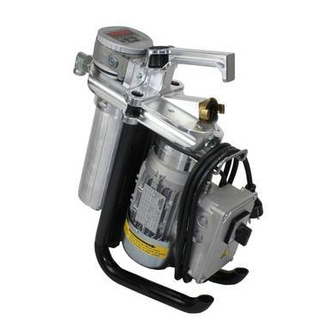
HYDAC FILTER SYSTEMS GMBH Overview of the filtration unit | 3 3.8 Operating elements on the filter unit The following operating elements can be found on the filter unit: Fig. 11: Components MFU-15 E / MFU-15 S IN Inlet OUT Outlet... - Page 38 3 | Overview of the filtration unit HYDAC FILTER SYSTEMS GMBH 30 Name plate of filter unit 110 Connector head 111 Transport handle 115 Vane pump 132 Cable holder 133 Clogging indicator / back-pressure indicator 140 Pressure relief valve 310 Electric motor...
-
Page 39: Filter Unit Working Principle
HYDAC FILTER SYSTEMS GMBH Overview of the filtration unit | 3 3.9 Filter unit working principle Fig. 12: The filter unit has a motor-pump assembly (310) for which the vane pump is integrated directly in the connector head (110). The drive motor (310) is, depending on the version, either an electric motor with direct current or alternating current or an air motor. - Page 40 3 | Overview of the filtration unit HYDAC FILTER SYSTEMS GMBH – A pressure relief valve (140) between the suction and pressure sides of the vane pump with ≈ 4 bar to protect against overpressure. – A protective screen (710) in the suction port. Access via the quick coupling (700).
-
Page 41: Transporting/Storing The Filter Unit
HYDAC FILTER SYSTEMS GMBH Transporting/storing the filter unit | 4 4 Transporting/storing the filter unit Fully empty the filter unit before transporting it or putting it into storage. Remove the used filter element and clean the inside of the filter bowl. -
Page 42: Storing The Filter Unit With Hoses Including Lances
4 | Transporting/storing the filter unit HYDAC FILTER SYSTEMS GMBH 4.1 Storing the filter unit with hoses including lances Is the filter unit equipped with the hoses including lances from Accessories. Plug the two lances into one another in the holder on the filter unit. -
Page 43: Setting Up / Assembly / Integration Of The Filter Unit
HYDAC FILTER SYSTEMS GMBH Setting up / assembly / integration of the filter unit | 5 5 Setting up / assembly / integration of the filter unit Observe the following notices for setting up the unit. NOTICE There is a risk of the unit falling over or slipping away due to vi-... -
Page 44: Fig. 15 Increasing The Stability / Adjusting The Feet
5 | Setting up / assembly / integration of the filter unit HYDAC FILTER SYSTEMS GMBH Fig. 15: Increasing the stability / adjusting the feet NOTICE Feet in other positions such as 0° or 44° The feet twist / the filter unit tips u To shift both feet, only use the intended positions for the feet and lock them subsequently. -
Page 45: Fig. 16 Adjusting The Feet 0°->44
HYDAC FILTER SYSTEMS GMBH Setting up / assembly / integration of the filter unit | 5 Fig. 16: Adjusting the feet 0°->44° To adjust the two feet from 0° to 44°, proceed as follows: 1. Fully unscrew both screws counterclockwise with an Allen key. -
Page 46: Fig. 17 Adjusting The Feet 44°->0
5 | Setting up / assembly / integration of the filter unit HYDAC FILTER SYSTEMS GMBH Fig. 17: Adjusting the feet 44°->0° To adjust the two feet from 44° to 0°, proceed as follows: 4. Fully unscrew both screws counterclockwise with an Allen key. -
Page 47: Avoiding Siphoning
HYDAC FILTER SYSTEMS GMBH Setting up / assembly / integration of the filter unit | 5 5.2 Avoiding siphoning If there is a height difference (ΔH) between the suction side and pressure side container/system, the lower line can develop a suction effect and trigger the siphoning effect between the communicating containers/systems. -
Page 48: Avoiding The Mixing Of Oils - Emptying The Filter Unit
5 | Setting up / assembly / integration of the filter unit HYDAC FILTER SYSTEMS GMBH 5.3 Avoiding the mixing of oils - Emptying the filter unit If you want to use the same oil for operation as in the previous operation, it is not serious if the oils are mixed. -
Page 49: Making The Electrical Connections
HYDAC FILTER SYSTEMS GMBH Setting up / assembly / integration of the filter unit | 5 5.4 Making the electrical connections Depending on the version, the filter unit has different drive mo- tors (different voltage / output / number of phases, etc.). Follow the instructions in the next section to electrically connect the fil- ter unit. - Page 50 5 | Setting up / assembly / integration of the filter unit HYDAC FILTER SYSTEMS GMBH 3. Check that the voltage and frequency are correct. You will find the filter unit's electrical data on the electric mo- tor's name plate.
-
Page 51: Connecting Filter Units With 400 V Ac, 3 Phase
HYDAC FILTER SYSTEMS GMBH Setting up / assembly / integration of the filter unit | 5 5.4.2 Connecting filter units with 400 V AC, 3 phase The 400 V AC, 3 phase version of the filter unit is equipped with an on/off switch, motor protection and connection plug;... -
Page 52: Connecting The Signal Cable (Only Mfu-15S9
5 | Setting up / assembly / integration of the filter unit HYDAC FILTER SYSTEMS GMBH 5.5 Connecting the signal cable (only MFU-15S9-...) The filter unit has a signal cable with plug (AMP T 3360 001) for signaling to the remote control. The relay in the connection terminal box has floating contacts to signal Voltage present and Pump switched on. - Page 53 HYDAC FILTER SYSTEMS GMBH Setting up / assembly / integration of the filter unit | 5 L Phase conductors M Electric motor W Neutral wire PE Protective conductor X1 Signal cable with plug connector BN Brown, code for color identification marking according to DIN IEC 60757...
-
Page 54: Connecting Pneumatically (Option - Compressed Air Motor)
5 | Setting up / assembly / integration of the filter unit HYDAC FILTER SYSTEMS GMBH 5.6 Connecting pneumatically (Option - Compressed air motor) When using the design with compressed air motor, connect the compressed air line to the filter unit. To ensure a constant flow, ensure that the compressed air supply is at 5 … 7 bar. -
Page 55: Connecting The Suction/Pressure Port
HYDAC FILTER SYSTEMS GMBH Setting up / assembly / integration of the filter unit | 5 5.7 Connecting the suction/pressure port Take into account the pressure loss when connecting suction/ pressure hoses. The suction / pressure hoses from the filter unit Accessories list [} 91] are matched to the filter unit. - Page 56 5 | Setting up / assembly / integration of the filter unit HYDAC FILTER SYSTEMS GMBH – Note that the nominal size of the connected hose/piping must correspond to the cross-section of the connection thread. – Make sure that the connection hoses/piping (suction side/ pressure side) do not cause any tension or vibrations to be carried over to the filter unit.
-
Page 57: Attaching / Connecting The Suction / Pressure Hoses (Accessories)
HYDAC FILTER SYSTEMS GMBH Setting up / assembly / integration of the filter unit | 5 5.8 Attaching / connecting the suction / pressure hoses (Accessories) Take into account the pressure loss when connecting suction/ pressure hoses. The suction / pressure hoses from the filter unit Accessories list [} 91] are matched to the filter unit. -
Page 58: Commissioning
5 | Setting up / assembly / integration of the filter unit HYDAC FILTER SYSTEMS GMBH 5.9 Commissioning Please follow the following steps for commissioning: 1. Insert a filter or empty element in the filter bowl. NOTICE! Operation without a filter element or empty element leads to leaks at the filter bowl. - Page 59 HYDAC FILTER SYSTEMS GMBH Setting up / assembly / integration of the filter unit | 5 10. Switch the filter unit on and monitor the suction action via the transparent suction hose. If the filter unit does not pump any fluid after a max. of 5 minutes of opera- tion, switch the filter unit off.
-
Page 60: Operation
6 | Operation HYDAC FILTER SYSTEMS GMBH 6 Operation To monitor the service life of the filter element during opera- tion, the filter unit is equipped with a contamination display (op- tical clogging pressure indicator). Visually check the optical clogging indicator daily. See chapter Observe the optical clogging indicator [} 60]... -
Page 61: Selecting Operating Modes
HYDAC FILTER SYSTEMS GMBH Operation | 6 6.2 Selecting operating modes On the filter unit, select the operating modes by using either a filter element (900) or an empty element (910). 900 Filter element 901 Empty element 6.2.1 Circulation pumping with filtration / filtration with dewatering For the "Circulation pumping with filtration"... -
Page 62: Circulation Pumping Without Filtration
6 | Operation HYDAC FILTER SYSTEMS GMBH 6.2.2 Circulation pumping without filtration Replace the filter element (900) with an empty element (910) for the "Circulation pumping without filtration" operating mode. A suitable empty element (910) can be found in Section Find- ing spare parts / accessories [} 88]... -
Page 63: Operation With Pump Nozzle (Optional)
HYDAC FILTER SYSTEMS GMBH Operation | 6 6.3 Operation with pump nozzle (optional) Observe the limited operating time during operation with the optional pump nozzle. NOTICE Continuous operation with closed pump nozzle The pump will be damaged. u Operate the filter unit with closed pump nozzle for a maxi- mum of 5 minutes. -
Page 64: Rectifying Errors
7 | Rectifying errors HYDAC FILTER SYSTEMS GMBH 7 Rectifying errors The following errors may occur during handling or operation of the filter unit: Malfunction Cause(s) Rectification No oil flow. The vane pump Make sure that is pumping the the vane pump... - Page 65 HYDAC FILTER SYSTEMS GMBH Rectifying errors | 7 Malfunction Cause(s) Rectification The viscosity of Check the vis- the fluid is too cosity of the high. fluid. Heat the fluid to achieve the per- missible viscos- ity. The is no power...
-
Page 66: Tab. 7 Error / Cause / Rectification
7 | Rectifying errors HYDAC FILTER SYSTEMS GMBH Malfunction Cause(s) Rectification Heat the fluid to achieve the per- missible viscos- ity. Leaks in the Wrong, missing, Check the filter unit / filter hous- or defective cartridge's seal- ing. sealing ring. -
Page 67: Performing Maintenance
HYDAC FILTER SYSTEMS GMBH Performing maintenance | 8 8 Performing maintenance In this chapter, you will find the description of the required maintenance activities and the qualifications of the staff needed to carry out these tasks. WARNING The hydraulic system is under pressure during operation... -
Page 68: Maintenance Table
8 | Performing maintenance HYDAC FILTER SYSTEMS GMBH 8.1 Maintenance table Additional infor- mation Observe the opti- cal clogging indi- cator Checking/clean- ing the protective screen Removing/in- stalling the pro- tective screen 8.4.1 Removing/in- stalling the push- in protective screen 8.4.2 Removing/in-... -
Page 69: Changing The Filter Element
HYDAC FILTER SYSTEMS GMBH Performing maintenance | 8 Additional infor- mation Checking/clean- ing the protective screen Changing the fil- ter element Changing the fil- ter element Checking/clean- ing the protective screen 1 - Operating personnel; 2 - Maintenance personnel; 3 - Spe- cialist personnel –... -
Page 70: Tab. 8 Overview Of The Filter Element / Type Of Operation
8 | Performing maintenance HYDAC FILTER SYSTEMS GMBH Filter element Operating mode NX9AM… AQUAMICRON Circulation pumping with filtra- tion and dewatering NX9-xxxxx-F empty element Circulation pumping without fil- tration Tab. 8: Overview of the filter element / type of operation NOTICE Missing filter element/empty element... - Page 71 HYDAC FILTER SYSTEMS GMBH Performing maintenance | 8 Filter element Empty element Proceed as follows to replace the filter element: 1x Wrench = 24 mm 1. With the filter unit switched on, remove the suction hose from the housing and aspirate air.
- Page 72 8 | Performing maintenance HYDAC FILTER SYSTEMS GMBH 4. Switch off the filter unit at the main switch and unplug the power connector. 5. Loosen the filter bowl (600) by turning it counterclock- wise. If required, use a wrench = 24 mm.
- Page 73 HYDAC FILTER SYSTEMS GMBH Performing maintenance | 8 7. Remove the used filter element. 8. Dispose of the used filter element and the residual oil volume in an environmentally friendly manner in accor- dance with the applicable guidelines and regulations.
- Page 74 8 | Performing maintenance HYDAC FILTER SYSTEMS GMBH 11. Check the O-rings on the filter element for damage. 12. Moisten the threaded connection on the filter bowl and the O-rings on the filter element lightly with fluid. NOTICE! Damaged O-rings cause leaks at the filter bowl.
- Page 75 HYDAC FILTER SYSTEMS GMBH Performing maintenance | 8 15. Rotate the filter bowl into the connector head by hand in clockwise direction and tighten it with a wrench = 24 mm with ≈ 40 Nm. 16. Remove and clean the protective screen (710)/(711) ac- cording to the description in Chapter Removing/in- stalling the protective screen [} 78].
-
Page 76: Removing/Installing The Quick Coupling
8 | Performing maintenance HYDAC FILTER SYSTEMS GMBH 8.3 Removing/installing the quick coupling For transportation or for cleaning/changing the protective screen, the suction hose must be removed. In the following, you can read about the procedure for the disassembly / as- sembly of the quick coupling at the suction connection. -
Page 77: Fig. 23 Removing/Installing The Hose Coupling
HYDAC FILTER SYSTEMS GMBH Performing maintenance | 8 Fig. 23: Removing/installing the hose coupling 700 Quick coupling on the filter unit 951 Quick coupling for suction hose 952 Clamping ring For removal, proceed as follows: 1. Switch the filtration unit off. -
Page 78: Removing/Installing The Protective Screen
8 | Performing maintenance HYDAC FILTER SYSTEMS GMBH Proceed as follows to install: 5. Attach the quick coupling (951) to the mating piece on the filter unit (700) and rotate the quick coupling (952) by ≈ 90° in clockwise direction. 6. Pull the clamping ring (952) at the quick coupling (951) by hand clockwise. - Page 79 HYDAC FILTER SYSTEMS GMBH Performing maintenance | 8 The two versions of the protective screens require different procedures for disassembly/assembly. You will find details on this in the subsequent chapters. BeWa MFU-15E_S 4391552a en-us lq 79 / 100...
-
Page 80: Removing/Installing The Push-In Protective Screen
8 | Performing maintenance HYDAC FILTER SYSTEMS GMBH 8.4.1 Removing/installing the push-in protective screen No tools are required. For removal, proceed as follows: ü Switch off the filtration unit and remove the lance from the reservoir and/or close the shut-off device in order to prevent any subsequent flow of the medium. - Page 81 HYDAC FILTER SYSTEMS GMBH Performing maintenance | 8 3. Reinstall the quick coupling, see Removing/installing the quick coupling [} 76]. O The assembly of the protective screen is complete. BeWa MFU-15E_S 4391552a en-us lq 81 / 100...
-
Page 82: Removing/Installing The Push-In Protective Screen
8 | Performing maintenance HYDAC FILTER SYSTEMS GMBH 8.4.2 Removing/installing the push-in protective screen 1x screwdriver = 2x16 mm For removal, proceed as follows: ü Switch off the filtration unit and remove the lance from the reservoir and/or close the shut-off device in order to prevent any subsequent flow of the medium. - Page 83 HYDAC FILTER SYSTEMS GMBH Performing maintenance | 8 6. Use the screwdriver = 2x16 to screw the protective screen (711) into the connector in the clockwise direc- tion. 7. Install the suction hose. O The assembly of the protective screen is complete.
-
Page 84: Checking/Cleaning The Protective Screen
8 | Performing maintenance HYDAC FILTER SYSTEMS GMBH 8.5 Checking/cleaning the protective screen To protect the pump from large contaminant particles there is a protective screen in the suction port. Clean the protective screen regularly. CAUTION Sharp-edged metallic chips / metallic particles in the protective... - Page 85 HYDAC FILTER SYSTEMS GMBH Performing maintenance | 8 NOTICE Damaged protective screen The filter unit will be damaged or destroyed u Never operate the filter unit with a damaged or defective protective screen. BeWa MFU-15E_S 4391552a en-us lq 85 / 100...
-
Page 86: Removing / Disposal
9 | Removing / Disposal HYDAC FILTER SYSTEMS GMBH 9 Removing / Disposal – Empty the product completely, including all of its compo- nents, before decommissioning. Disconnect or remove the electric, pneumatic or hydraulic connections. – Dispose of the packaging material in an environmentally friendly manner. -
Page 87: Appendix
HYDAC FILTER SYSTEMS GMBH Appendix | Appendix In this annex, you will find supplementary information on the product. Finding a Customer Service team The contact data such as the telephone numbers, e-mail and mailing addresses for the hotline, product support, customer... -
Page 88: Finding Spare Parts / Accessories
Use only original spare parts and accessories. When ordering spare parts and accessories make sure to always indicate the exact unit designation and the serial number. The following spare parts are available for the product: Fig. 24: Spare parts MFU-15E / MFU-15S / MFU-10P Item Qty. Tool Auxiliary Part no. -
Page 89: Tab. 10 Spare Parts List
HYDAC FILTER SYSTEMS GMBH Appendix | Item Qty. Tool Auxiliary Part no. Connector set consisting of: - supports and elbow connector at the outlet - screw plugs including seals (FKM) Dry-running protection consisting of: - hose including hose nipple Set of feet consisting of:... -
Page 90: Finding The Filter Elements
| Appendix HYDAC FILTER SYSTEMS GMBH Finding the filter elements The following filter elements with different functions are avail- able. Item Qty. Tool Part no. Filter element, 2 µm DIMICRON NX9DM002-F 4265955 Filter element, 5 µm DIMICRON NX9DM005-F 4265956 Filter element, 10 µm DIMICRON... -
Page 91: Accessories List
HYDAC FILTER SYSTEMS GMBH Appendix | Accessories list The following accessories are available for the filter unit: Item Qty. Tool Auxiliary Part no. Suction/pressure hose with lances, PVC / PVC 4270478 hose length: 2.5 m/2.5 m, lance length: 0.25 m... -
Page 92: Tab. 14 Accessories List
| Appendix HYDAC FILTER SYSTEMS GMBH Item Qty. Tool Auxiliary Part no. Counter 4270518 Pump nozzle 4270561 Pump nozzle + counter Only for viscosity 4270519 < 200 mm²/s Tab. 14: Accessories list 92 / 100 BeWa MFU-15E_S 4391552a en-us lq... - Page 93 Pressure loss formula................Fig. 20 Optical clogging indicator ................. Fig. 21 Filter element.................... Fig. 22 Empty element ..................Fig. 23 Removing/installing the hose coupling ............. Fig. 24 Spare parts MFU-15E / MFU-15S / MFU-10P.......... BeWa MFU-15E_S 4391552a en-us lq 93 / 100...
- Page 94 Index of Tables HYDAC FILTER SYSTEMS GMBH Index of Tables Tab. 1 Impressum....................Tab. 2 Documentation Representative ..............Tab. 3 Target group ..................... Tab. 4 Scope of delivery ..................Tab. 5 Technical Data ..................Tab. 6 Loading of the relay contacts ..............
-
Page 95: Glossary
HYDAC FILTER SYSTEMS GMBH Glossary Glossary General Terms and Conditions The 1 SN high-pressure hose has a The General Terms and Conditions steel mesh insert and, on the inside, are available at our home page is is made of oil-resistant synthetic www.hydac.com ->... -
Page 96: Index
Index HYDAC FILTER SYSTEMS GMBH Index Servicepartners 87 siphoning effect 47 Branches 87 stability 43 Support 87 calculating pressure loss 55 Terms and Conditions 14 Terms of Delivery 14 decommissioning 86 disposal 86 warranty 14 exclusion of liability 14 Hotline 87...
Need help?
Do you have a question about the MFU-15E and is the answer not in the manual?
Questions and answers