
Related Manuals for Keba KeDrive D3-DA 3 Series


Summary of Contents for Keba KeDrive D3-DA 3 Series
- Page 1 KeDrive D3-DA 3xx/x Axis module Project engineering manual V 1.07 Translation of the original manual...
- Page 2 Specifications are subject to change due to further technical developments. Details presented may be subject to correction. All rights reserved. Gewerbepark Urfahr, 4041 Linz, Austria, Phone: +43 732 7090-0, KEBA AG Headquarters: Fax: +43 732 7309-10, keba@keba.com For information about our subsidiaries please look at www.keba.com.
- Page 3 EG directives and 1.05 07-2017 UL added hasl standards Several corrections (Type plate, Mounting, tech. 1.06 04-2018 Various chapter hasl data, ...) 1.07 10-2018 Various chapter Several updates (Mounting, Tech. data, ...) hasl, hli Project engineering manual V1.07 © KEBA...
- Page 4 D3-DA 3xx/x Project engineering manual V1.07 © KEBA...
-
Page 5: Table Of Contents
EMC requirements ................... 5.1.1 Requirements to the connectors ............Space requirements..................Mounting the module ..................5.3.1 For wall mounting ................5.3.2 For cooling element ................Dismantling of the module ................Air conditioning and ventilation ................ Project engineering manual V1.07 © KEBA... - Page 6 Example: STO and SBC control via light grid ........8.4.4 Example: STO and SBC control directly via supply module ....Validation of safety functions ................Validation of STO safety function..............Validation of SBC safety function..............Project engineering manual V1.07 © KEBA...
- Page 7 Environmental and surrounding conditions........104 13.3 CE marking ...................... 104 13.4 UL certification ....................104 13.5 Loads on the mains due to harmonics ............. 105 14 Declaration of conformity..................106 14.1 With safety ....................... 106 Project engineering manual V1.07 © KEBA...
- Page 8 Connection cable XW H0x-xxx ............115 16.3.3 Signal cable XW E10-xxx ..............116 16.3.4 Signal cable XW R10-xxx ..............117 16.3.5 Signal cable XW 020 ................. 117 16.3.6 Signal cable XW 021 ................. 118 Index ..........................120 Project engineering manual V1.07 © KEBA...
-
Page 9: Introduction
Basic technical training (technical college, engineer training or corresponding professional experience). Knowledge about: ● current valid safety regulations, Project engineer ● fundamental validation concepts according to EN ISO 13849, ● method of operation of a PLC, ● the application. Project engineering manual V1.07 © KEBA... -
Page 10: Intended Use
● diagnostic options, ● systematic fault analysis and remedial action. Intended use The D3-DA 3xx/x is intended for installation in stationary electrical systems or machines and was developed for controlling of drives. Project engineering manual V1.07 © KEBA... -
Page 11: Notes On This Document
D3-DU 3x5/x. Caution Also take care of the information in the safety manual "Functional safety" provided by KEBA. Information The compliance of EMC directives can only be assumed under attention of chapter "CE Certification" as well as the information of cahpter "Connection and wiring", also the cable and additional components are used as speci-... -
Page 12: Content Of This Document
D3-DA 3xx/x. Because of the fact that customer variants may differ in their appearance (e.g. with a different front cover) from the KEBA standard variant, the pic- tured devices used in this manual may differ in their appearance from the devices used by you. -
Page 13: Ethercat Declaration
D3-DA 3xx/x Introduction Doc.No. Name Target group ● Safety engineer for "functional safety" ● Project engineer DE: 1008535 ● Electrician KEBA - Functional safety safety manual ● Programmer EN: 1008536 ● Start-up operator ● Service technician ● Electrician DE: 1008773 ●... -
Page 14: Safety Notes
Safety information Describes important safety-related requirements or informs about essential safety-related coherences. Information Identifies practical tips and useful information. No information that warns about potentially dangerous or harmful functions is contained. Project engineering manual V1.07 © KEBA... -
Page 15: General Safety Instructions
● Commissioning is only permitted for persons, who understand the lan- guage of the enclosed product documentation. ● All work concerning transportation, installation and commissioning as well as repair and maintenance must only be carried out by qualified ex- pert personnel. Project engineering manual V1.07 © KEBA... - Page 16 ● The D3-DA 3xx/x contains safety-relevant functions (e.g. STO). For safety-relevant control tasks and personnel security a control of KEBA in the variant D3-DU 3x5/x with correspondent safety related peripheral de- vices must be used. Details can be found in the safety manual "Func- tional safety".
- Page 17 KEBA, report these promptly to KEBA. Furthermore, it is asked to send all safety-oriented products that have failed due to a defect for purposes of analysis to KEBA, even if they are consid- ered as non-repairable.
-
Page 18: Safety Instructions For Personal Safety
● The device must only be opened by trained specialized personnel. They must only carry out maintenance work that is explicitly permitted by KEBA (see chapter "Maintenance"). Project engineering manual V1.07 © KEBA... -
Page 19: Esd Information
...). ● Use ESD protection even for defective modules. Generally avoid, for modules which are mounted in an enclosure, direct con- tact with any accessible electronic components, such as non-equipped ter- minals. Project engineering manual V1.07 © KEBA... -
Page 20: Description Of Module
... EtherCAT interface ... Digital inputs ... Encoder interface ... Digital inputs safety function Bottom view The following graphic shows the full expansion of each size, depending on variant less interfaces can be on the module. Project engineering manual V1.07 © KEBA... -
Page 21: Type Plate
Type plate on left side of module Fig. 3-3: Type plate 1 ... Manufacturer and manufacturer ad- ... Product group dress ... Material name ... Technical data ... Material number/revision number ... Serial number ... Country of origin Project engineering manual V1.07 © KEBA... -
Page 22: Overview D3-Da 3Xx/X Variants
... Data matrics code ... Production date (month/year) Overview D3-DA 3xx/x variants Example: DA 3 1 0 / A - 01 0 0 - 00 Products and series DA 3 Axis Single axis Double axis Project engineering manual V1.07 © KEBA... -
Page 23: Accessories
Accessories 3.5.1 Connector set Caution Only compatible mating connectors that are approved by KEBA must be used. The technical data for the terminals are contained in the technical data sheet of the manufacturer of the female connectors. Project engineering manual V1.07... - Page 24 Description of module D3-DA 3xx/x Connector set suitable Connector set Order number KEBA. For control cable X25/A, X26/ D3-XT 230/A 94801 D3-XT 231/A Motor connector X31/x 94503 *) *) The connector set fits for single axis module. For double axis or tripple axis the connector set must ordered proportionally.
-
Page 25: Displays And Operating Elements
At the EtherCAT connectors are the following LEDs. Fig. 4-7: EtherCAT connections (X40A / X40B) ... Link/Acitivty LED ... RUN LED ... ERR LED Link/Activity LED Indication Meaning Dark No connection Green flashing Transmission of data Project engineering manual V1.07 © KEBA... - Page 26 Indication of the EtherCAT operating state OPERATIONAL ERR LED Indication Meaning Dark No EtherCAT error Indication of an EtherCAT error according to "ETG.1300 Red flashing EtherCAT Indicator and Labeling Specification" (Table "ERR Indicator States") Project engineering manual V1.07 © KEBA...
-
Page 27: Mounting And Installation Instructions
Max. pollution severity 2 to EN 606641. (See 12.6 Ambient conditions). Adding and orientation The modules must be mounted side by side directly without distance. Con- necting power supply connects the modules (see chapter "Connection of supply voltages via busbars"). Project engineering manual V1.07 © KEBA... - Page 28 Fig. 5-8: Mounting order ... D3-DU 3xx/x control module ... D3-DP 3xx/x supply module ... D3-DA 3xx/x axis module ... Further D3-DA 3xx/x axis module Project engineering manual V1.07 © KEBA...
-
Page 29: Emc Requirements
● Use shielded cables: In capt. "Connection technology" are all cables lis- tet, which are available at KEBA. It is recommended to use this cables, because all EMC tests were executed with this cables and so they are tested accordingly. -
Page 30: Requirements To The Connectors
(lower end of the front plate) again. The following (RT-)Ethernet connectors can be affected: Fig. 5-9: Cable shield ... Cable shield with shield clamp ... Control module ... Supply module ... Cabinet Project engineering manual V1.07 © KEBA... - Page 31 For connecting third-party motors, equivalent cables must be used. Connectors for the motor All motor cables must be shielded. All available cables from KEBA are listed in the appendix. For connecting third-party motors, equivalent cables must be used.
- Page 32 The reason for this is, that because of switching processes and indi- rect lightning strikes low-frequency high compensating currents can be cre- ated, which may be too high for shieldings and especially for the shield con- nectors and can so damage the shield connection. Project engineering manual V1.07 © KEBA...
-
Page 33: Space Requirements
Fig. 5-11: Mounting clearances (in mm) The bend radius of the connecting cables must be taken into account. (Up to 3 x 10 mm ca. 48 - 98 mm depending on the cable version.) Project engineering manual V1.07 © KEBA... - Page 34 3 x 16 mm ca. 150 - 200 mm depending on the cable version.) KeDrive D3 example (with control module with safety functionality and with supply module) Example with one axis module size 1 (BG1) Project engineering manual V1.07 © KEBA...
- Page 35 D3-DA 3xx/x Mounting and installation instructions Fig. 5-13: Dimension with size 1 Dimensions Height: 310 mm Width: 165 mm Depth: 241 mm Example with one axis module size 1 (BG1) and size 2 (BG2) each Project engineering manual V1.07 © KEBA...
-
Page 36: Mounting The Module
Depth: 241 mm Mounting the module The D3-DA 3xx/x is exclusively intended for the vertical installation on a plane, stable, conductive and grounded mounting plate by means of bolted connections. Position of mounting holes: Project engineering manual V1.07 © KEBA... -
Page 37: For Wall Mounting
Align all the devices along the top edge of the device. 4) Mount the devices successively on the cooling plate. Tighten the screws evenly so that the thermal resistance remains as low as possible. The contact area must be metallic, bare and conductive. Project engineering manual V1.07 © KEBA... -
Page 38: Dismantling Of The Module
In this case the cooled rear panel for mounting the module is called as cooler. Dismantling of the module During the disassembly of the module it needs to be ensured and checked that it is absolutely de-energized (see chap. "Power supply"). Project engineering manual V1.07 © KEBA... -
Page 39: Air Conditioning And Ventilation
(= heat loss is discharged to the out- side via the cabinet walls), always fit an internal air circulation fan. The spec- ified environmental conditions must to be adhered mandatorily indepen- dently of this. Project engineering manual V1.07 © KEBA... -
Page 40: Connections And Wiring
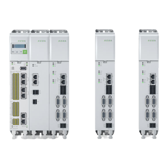
The following pages contain detailed layout diagrams on the D3-DA 3xx/x single-axis, double-axis and triple-axis modules. Fig. 6-15: Overview D3-DA 3xx/x axis modules ... Status axis 1 ... Status axis 2 ... Status axis 3 Project engineering manual V1.07 © KEBA... - Page 41 For variants with Hipferface DSL motor temperature mon- X31C Power connection motor 3 itoring happen via Hiperface DSL signales D3-DA 3xx/x single-axis mod- D3-DA-310/x D3-DA 3xx/x double-axis D3-DA-320/x module D3-DA 3xx/x triple-axis mod- D3-DA-330/x Project engineering manual V1.07 © KEBA...
-
Page 42: Single-Axis Module
X48B ... Additional encoder connection (axis 1) For informations about the status LEDs of the axes see 4.1 Status LEDs of axis. Single-axis module encoder axis 1 Fig. 6-17: Pin assignment connector X48A single-axis module Project engineering manual V1.07 © KEBA... - Page 43 + SIN S2 / SIN+ (B+) - Safety Sense + Safety Sense - CLK + CLK - Fig. 6-18: Pin assignment connector X48B single-axis module SinCos and TTL max. +5.4 V / max. 250 mA Project engineering manual V1.07 © KEBA...
-
Page 44: Double-Axis Module
... LED red (State axis 2 ERR LED red) X48D ... Additional encoder connection ... LED green (axis 2) For informations about status LEDs of the axes see 4.1 Status LEDs of the axis. Project engineering manual V1.07 © KEBA... - Page 45 R2 (resolver excit. -) R1 (resolver excit. +) + SIN S2 / SIN+ (B+) - Safety Sense + Safety Sense - CLK + CLK - Fig. 6-21: Pin assignment connector X48B double-axis module SinCos and TTL Project engineering manual V1.07 © KEBA...
- Page 46 S1 / COS+ (A + COS max. +5.4 V / max. 250 mA Data + Data - REFSIN S4 / SIN- (B-) 10 V / 110 mA R2 (resolver excit. -) R1 (resolver excit. +) Project engineering manual V1.07 © KEBA...
- Page 47 + SIN S2 / SIN+ (B+) - Safety Sense + Safety Sense - CLK + CLK - Fig. 6-23: Pin assignment connector X48D double-axis module SinCos and TTL max. +5.4 V / max. 250 mA Project engineering manual V1.07 © KEBA...
-
Page 48: Triple-Axis Module
X26A ... Digital inputs safety function ... LED green Axis 1 ... LED yellow For informations about the status LEDs of the axes see 4.1 Status LEDs of axis. Triple-axis module encoder axis 1 Project engineering manual V1.07 © KEBA... - Page 49 + SIN S2 / SIN+ (B+) - Safety Sense + Safety Sense - CLK + CLK - Fig. 6-26: Pin assignment connector X48B triple-axis module SinCos and TTL max. +5.4 V / max. 250 mA Project engineering manual V1.07 © KEBA...
- Page 50 +5.4 V / max. 250 mA Data + Data - REFSIN S4 / SIN- (B-) 10 V / 110 mA R2 (resolver excit. -) R1 (resolver excit. +) + SIN S2 / SIN+ (B+) - Safety Sense + Project engineering manual V1.07 © KEBA...
-
Page 51: Grounding
Connect the PE connections (screw socket M4) on the supply module, the axis modules and the controller in series with the PE connections (profile 16 mm²) included in the delivery as shown in the following figure Project engineering manual V1.07 © KEBA... - Page 52 Protective earth conductor with mains cable crosssection ≥ 10 mm² Fig. 6-29: Protective earth conductor ... D3-DU 3xx/x control module ... D3-DP 3xx/x supply module ... D3-DA 3xx/x axis module size 1 ... D3-DA 3xx/x axis module size 2 Project engineering manual V1.07 © KEBA...
- Page 53 Protective earth conductor with mains cable crosssection < 10 mm² Fig. 6-30: Double protective earth conductor ... D3-DU 3xx/x control module ... D3-DP 3xx/x supply module ... D3-DA 3xx/x axis module ... Mains choke (optional) Project engineering manual V1.07 © KEBA...
-
Page 54: Electrical Isolation Method
Low voltage = AC: U ≤ 1000 V Simple isolation low voltage to PELV PELV (Protective Extra Low Voltage) = DVC A according to EN 61800-5-1 max. 25 V AC or 60 V DC Project engineering manual V1.07 © KEBA... - Page 55 The inputs SDI00/SDI01/GND are isolated against SDI02/SDI03/GND. ● All inputs are isolated against 24 V power supply. ● All inputs are isolated against PE. ● Maximum allowed isolation voltage: PELV ● Maximum allowed input voltage: -60 V ... 60 V Project engineering manual V1.07 © KEBA...
-
Page 56: Connection Of Supply Voltages Via Busbars
(2.1 Nm / 18.5 lb-in) that they cannot come loose. On the usage of connection elements that do not meet the requirements, KEBA does provide any guarantee for stable, reliable op- eration. Also expires certification marks and CE conformity. -
Page 57: Voltage Supply
The busbars supplied are to be used for the electrical coupling of the de- vices. On the usage of connection elements that do not meet the require- ments, KEBA does provide any guarantee for stable, reliable operation. Fig. 6-33: D.c. link ●... -
Page 58: Overview Busbars
They can be programmed individually via the EtherCAT bus system. The in- puts DI09 and DI10 are suitable for touch probe applications due to their fast signal processing. The axis assignment can also be programmed via the EtherCAT bus system. Project engineering manual V1.07 © KEBA... - Page 59 At the digital inputs only PNP sensors are allowed to be connected. Selection list, function of the control inputs Pos. limit switch Neg. Limit switch Axis 1/2/3 No function (LimP) (LimN) DI01 LimP(1) LimN(2) DI02 LimP(1) LimN(2) DI03 LimP(1) LimN(2) Project engineering manual V1.07 © KEBA...
-
Page 60: Safe Digital Input (Terminal X26A)
D3-DA 3xx/x... -
Page 61: Motor Connection
4) If fitted, connect the motor brake to X31/A / X31/B / X31/C -1, 2. The mo- tor cables from KEBA have a shielded wire pair for motor brake inte- grated and the shield has contact with the connectors on both sides Motor cable All motor cables must be shielded. - Page 62 Fig. 6-38: Connection of a servomotor with motor holding brake ... Control motor brake ... Brake (+) ... Brake (-) ... Supply for brake The temperature sensor connection is shown in the version with "standard encoder interface". Project engineering manual V1.07 © KEBA...
-
Page 63: Monitoring Output Motor Holding Brake
7.5 ms (depending on the load) and a minimum time window of 1.5 ms. Information Due to this brief shutdown, on high impedance loads the "Time window ex- ceeded" error may be triggered. Project engineering manual V1.07 © KEBA... -
Page 64: Specification Of Motor Connections
It cannot be excluded that switching in the motor cable will result in the de- struction of the axis module. To interrupt the supply of power to the servo motor, the safety function STO is available (See 8 Safety functions). Project engineering manual V1.07 © KEBA... -
Page 65: Specification Of Ethercat Connection Interface
They can be used for a connection to the left, nearby module. 6.9.1 Pin assignment Fig. 6-41: RJ45 plug Pin-No. Signal designation Input/Output Tr. Data+ Transmit Data + Output Tr. Data- Transmit Data - Output Project engineering manual V1.07 © KEBA... -
Page 66: Encoder Connections
6.10 Encoder connections All encoder connections are located on the front of the device. All encoder cables must be shielded. The cables available from KEBA are listed in chap- 16.3 Connection technology. Equivalent shielded cables must be used for the connection of motors from other manufacturers. -
Page 67: Connection For High-Resolution Encoder
Single- and multiturn encoder, e.g. SRS50, FACE® Interface SRM50 The usage of encoders not included in the range supplied by KEBA requires special approval by KEBA. The maximum signal input frequency is 500 kHz. Encoders with a supply voltage of 5 V ± 5 % must use the supply voltage from pin 3 (max. 5.4 V). -
Page 68: Operation On Special Systems
6.12 DIP-Switch (S-ADR) The DIP-Swith S-ADR is located on the bottom side of the module and serves for configuration of the safety functions of the D3-DA 3xx/x. For more details see 8 Safety functions. Project engineering manual V1.07 © KEBA... -
Page 69: Configuration
The configuration of the D3-DA 3xx/x is done via configuration tools inte- grated in the delivery. For information to configuration see online help of D3-DA 3xx/x. For informa- tion of parametrization of a drive see functional description "KeDrive D3 - Firmware for axis controller devices". Project engineering manual V1.07 © KEBA... -
Page 70: Safety Functions
The logic interrupts the supply voltage for the pulse amplifier for the operation of the power stage. By means of two inputs the motor is prevented from generating torque using a two-channel process. Project engineering manual V1.07 © KEBA... -
Page 71: Configuration Of Sto Safety Function
STO1: Axis 1 Separate switching of all existing axis STO2: Axis 2 (Default setting) Axis 3 STO1: Axis 1 Axis 2 Axis 3 Common switching of all existing axis STO2: Without function Project engineering manual V1.07 © KEBA... -
Page 72: Sbc (Safe Brake Control)
EN 61800-5-2, EN, EN ISO 13849-1 „PL d“ category 3 and EN 61508 / EN 62061 „SIL 2“. You will find the safety-related characteristics in chapter „Technical Data“. The SBC shutdown takes place within 3 ms. Project engineering manual V1.07 © KEBA... -
Page 73: Configuration Sbc Safety Function
STO. Settings Description Function affect to STO1: STO axis 1-3 SBC deactivated SBC deactivated (Default setting) STO2: Without function STO1: STO axis 1-3 SBC axis 1-3 SBC activated STO2: Without function Project engineering manual V1.07 © KEBA... -
Page 74: Diagnosis Via Cross Circuit Test
All other combinations on the DIP switch are invalid and lead at the latest on demand of safety function (e.g. validating of safety function) to an error message and the system changes into safe state. Project engineering manual V1.07 © KEBA... -
Page 75: Recommended Connection Examples
The control of safety function STO is done via corresponding logical pro- cessing of the safety control, whereby the safety function STO and SBC of the single axis modules are controlled from the safety control via separate outputs Project engineering manual V1.07 © KEBA... - Page 76 Should safety functions STO and SBC of the single axis modules controlled via same outputs of the safety control, the wiring can be copied as shown below: Fig. 8-44: STO and SBC control ... D3-DU 3x5/x ... D3-DA 3xx/x Project engineering manual V1.07 © KEBA...
-
Page 77: Example: Sto Without Sbc Control Via Safety Control
DIP switch, because SBC is always released with STO1. Otherwise no SBC is released on the requested STO2 or SBC will be activated on all axes with the requested STO1, although axis 2 and 3 have no STO! Project engineering manual V1.07 © KEBA... -
Page 78: Example: Sto And Sbc Control Via Light Grid
The cross circuit test must be configured suitable via the DIP switch. Information It is recommended to use a safety control and use prefered one of the above mentioned connection examples! Project engineering manual V1.07 © KEBA... -
Page 79: Validation Of Safety Functions
Motor axis coasts down or STO input becomes "inac- Test step 1 there is no torque and no er- tive". ror message occurs. Axis module can apply Test step 2 STO input becomes "active". torque. Project engineering manual V1.07 © KEBA... -
Page 80: Validation Of Sbc Safety Function
The safety system switchs off One of the testoutputs is break and torque after max. Test step 1 shorting against 24 V 2,4 s and an error message occures. Only applies in case SBC is active. Project engineering manual V1.07 © KEBA... - Page 81 D3-DA 3xx/x Safety functions Information A restart is necessary to start the system again. Project engineering manual V1.07 © KEBA...
-
Page 82: Diagnosis
Axis ready to switch on Axis switched on Operation enabled Quickstop Error code Fault reaction active Error code Error (Fault) LED green long = Operation with real motor LED green short = Operation with simulated motor Project engineering manual V1.07 © KEBA... -
Page 83: Maintenance
The D3-DA 3xx/x is basically maintenance free, however, the fundamental, cyclical validation of safety functions needs to be considered. In case of er- ror replace the device. It is asked to send back defect devices to KEBA. 10.1 Update firmware The firmware can be updated via the tool DriveManager, included in the de- livery. -
Page 84: Disposal
● The materials are recyclable in accordance with their labeling. You can make an important contribution to protecting our envi- ronment by reusing, renewing and recycling materials and old appliances. Project engineering manual V1.07 © KEBA... -
Page 85: Technical Data
For Variants with limitation of output frequency the max. output frequency is limited to 599 Hz. Axis module Dissipation @ (400 V / 4 kHz / I ) in the interior: ● D3-DA 310/A-01xx: 60.5 W Project engineering manual V1.07 © KEBA... -
Page 86: Current Data D3-Da 3X0/X-01Xx
1.5 A 1.3 A 0.7 A 0.3 A Maximum current for 10 s: 2.6 A 1.4 A 0.6 A Maximum current for 500 ms: 4.5 A 4.0 A 2.6 A 1.8 A 1.4 A Project engineering manual V1.07 © KEBA... -
Page 87: Current Data D3-Da 3X0/X-03Xx
● D3-DA 310/x-06xx: 0.5 A ● D3-DA 310/x-12xx: 0.5 A ● D3-DA 320/x-06xx: 0.7 A ● D3-DA 320/x-12xx: 0.8 A ● D3-DA 330/x-06xx: 0.9 A ● D3-DA 330/x-12xx: Project engineering manual V1.07 © KEBA... - Page 88 D3-DA 320/A-12xx: 118 W ● D3-DA 330/A-06xx: 98.8 W ● D3-DA 330/A-12xx: 141 W ● D3-DA 310/B-06xx: 32 W ● D3-DA 310/B-12xx: 64 W ● D3-DA 320/B-06xx: 47 W ● D3-DA 320/B-12xx 85 W Project engineering manual V1.07 © KEBA...
-
Page 89: Current Data D3-Da 3X0/X-06Xx
10.2 A 6.6 A 4.6 A 3.5 A 12.2.2 Current data D3-DA 3x0/x-12xx Information Current data per axis in the axis module 230/400/480 V AC refers to the supply voltage for the supply module. Project engineering manual V1.07 © KEBA... -
Page 90: D3-Da 320/X-16Xx, D3-Da 310/X-18Xx
15.5 A 12.4 A Maximum current at F = 0 Hz: 36 A 26 A 14.4 A 10.7 A 8.5 A 12.3 D3-DA 320/x-16xx, D3-DA 310/x-18xx Control section Control voltage: 24 V DC ±10 % Project engineering manual V1.07 © KEBA... - Page 91 ● D3-DA 320/B-16xx: 95 W ● D3-DA 310/B-18xx: 66 W Dissipation @ (400 V / 4 kHz / P ) via cooling element/cold plate: ● D3-DA 320/x-16xx: 233 W ● D3-DA 310/x-18xx: 120 W Project engineering manual V1.07 © KEBA...
-
Page 92: Current Data D3-Da 320/X-16Xx
31.4 A 20.3 A 15.8 A 12.3 A At U = 480 V supply 2 kHz 4 kHz 8 kHz 12 kHz 16 kHz Nominal current: 18 A 18 A 13.2 A 9.2 A Project engineering manual V1.07 © KEBA... -
Page 93: D3-Da 310/X-24Xx, D3-Da 310/X-32Xx
599 Hz. Axis module Dissipation @ (400 V / 4 kHz / I ) in the interior: ● D3-DA 310/A-24xx 103 W ● D3-DA 310/A-32xx 112 W ● D3-DA 310/B-24xx: 78 W Project engineering manual V1.07 © KEBA... -
Page 94: Current Data D3-Da 310/X-24Xx
37.4 A Maximum current for 500 ms: 100 A 100 A 74.8 A 50.8 A 37.4 A Maximum current at F = 0 Hz: 64 A 64 A 51.4 A 35 A 25.7 A Project engineering manual V1.07 © KEBA... -
Page 95: General Safety Specifications
"high demand" according to EN 61508 (high Dimensioning the operating mode: demand rate) Reaction time: 3 ms 12.6 Ambient conditions According to EN 61800-1 and the included and referenced environment clas- sifying of standards IEC 60421-3. Project engineering manual V1.07 © KEBA... - Page 96 The absolute humidity is limited to max. 60 g/m³. This means, at 70 °C for example, that the relative humidity may only be max. 40 %. Mounting height higher than 2,000 m is possible under the following condi- tions: Project engineering manual V1.07 © KEBA...
-
Page 97: Safe Digital Inputs
Duration of the test pulses between 0.75 ms and 2 ms results an unwanted shutdown after unpredictable time. This information applies irrespective of wheter the monitoring of external test pulses is switched off or on. Project engineering manual V1.07 © KEBA... -
Page 98: Digital Inputs
0 V ≤ UL ≤ 5 V Galvanic isolation toward the control elec- tronics: Galvanic isolation of the inputs: Reaction time HIGH: < +/- 0.75 us Reaction time LOW: < +/- 5.5 us Wiring: Sink Project engineering manual V1.07 © KEBA... -
Page 99: Dimensions, Weight
D3-DA 3xx/x Technical data 12.9 Dimensions, weight Size 1 Dimensions with cooling element Fig. 12-48: Dimensional drawing, measures in mm Project engineering manual V1.07 © KEBA... - Page 100 Technical data D3-DA 3xx/x Dimensions with cold plate Fig. 12-49: Dimensional drawing, measures in mm Project engineering manual V1.07 © KEBA...
- Page 101 D3-DA 3xx/x Technical data Size 2 Dimensions with cooling element Fig. 12-50: Dimensional drawing, measures in mm Project engineering manual V1.07 © KEBA...
- Page 102 188.5 mm / 170 mm Weight: ● D3-DA 3x0/A (Size 1): 2,650 g ● D3-DA 3x0/B (Size 1): 2,300 g ● D3-DA 3x0/A (Size 2): 5,100 g ● D3-DA 3x0/B (Size 2): 3,700 g Project engineering manual V1.07 © KEBA...
-
Page 103: Ec Directives And Standards
Safety of machinery - Electrical equipment of EN 60204-1:2006 + A1:2009 machines - Part 1: General requirements Adjustable speed electrical power drive sys- EN 61800-5-1:2007 tems - Part 5-1: Safety requirements - Elec- trical, thermal and energy Project engineering manual V1.07 © KEBA... -
Page 104: Environmental And Surrounding Conditions
Use the following UL-certified device wiring (mains, motor and control ca- bles) only: ● Copper conductors rated min. 75 °C. ● Recommended terminal connectors and specified tightening torques for terminals (see "Connections and wiring") Project engineering manual V1.07 © KEBA... -
Page 105: Loads On The Mains Due To Harmonics
If you use our drives as a compo- nent in your machine / system, the directive of the standards must be checked for the entire machine / system. Project engineering manual V1.07 © KEBA... -
Page 106: Declaration Of Conformity
Declaration of conformity D3-DA 3xx/x Declaration of conformity 14.1 With safety Project engineering manual V1.07 © KEBA... - Page 107 D3-DA 3xx/x Declaration of conformity Project engineering manual V1.07 © KEBA...
- Page 108 Declaration of conformity D3-DA 3xx/x Project engineering manual V1.07 © KEBA...
-
Page 109: Appendix: Estimation Of System Performance
A supply module with 10 kW supplies a triple axis module with 12 A. With sufficient DC link capacity, the supply module can provide permanently up to 10 kW effective power at the DC link. Module Power DC link capacity Supply module 10 kW 330 μF Project engineering manual V1.07 © KEBA... - Page 110 AC, the effective power of the DC link is 1 kW. The peak power is limited to 2 kW. For 1 kW effective power, additional DC link capacitiy of 900 µF is nec- cessary. Project engineering manual V1.07 © KEBA...
-
Page 111: Appendix: Further Components
The following cooling plates and cooling elements are available: Designation Material number Cooling element D3-XM 310-055 95179 Cooling plate D3-XM 300-060 95521 Cooling plate D3-XM 300-080 102204 16.1.1 Cooling Element D3-XM 310-055 Fig. 16-52: Dimensions of cooling element D3-XM 310-055, dimensions in mm Project engineering manual V1.07 © KEBA... -
Page 112: Cooling Plate D3-Xm 300-060
Appendix: Further components D3-DA 3xx/x 16.1.2 Cooling plate D3-XM 300-060 Fig. 16-53: Dimensions of cooling plate D3-XM 300-060, dimensions in mm ... all thread M4 passage Project engineering manual V1.07 © KEBA... -
Page 113: Cooling Plate D3-Xm 300-080
D3-DA 3xx/x axis module (for use on the D3-DP 3xx/x supply module) ● Brake resistor - converts surplus regenerated energy into heat and in this way permits an even more dynamic movement process (for usage on theD3-DP 3xx/x supply module). Project engineering manual V1.07 © KEBA... -
Page 114: Connection Technology
Caution If D3-DA 3xx/x connection cables are equipped with an user specific con- nector and not with KEBA proposed connector, reduced electromagnetic im- munity is possible. In this case the user has to ensure that the requirements of the EMC directive are met. -
Page 115: Connection Cable Xw H0X-Xxx
... Cable of length L ... Not connected Pin assignment at connection cable XW H0x-xxx Connector S2 Connector S1 Color of wires / Signal (Axis module- (Motor-sided) identification sided) Black, white imprint U U Green-yellow n.c. Project engineering manual V1.07 © KEBA... -
Page 116: Signal Cable Xw E10-Xxx
Color of wires / Signal (Drive control (Motor-sided) identification system-sided) White Brown Ref Sin Blue Ref Cos Green Data + Data - Black Sin + Purple Cos + Brown n.c. n.c. n.c. n.c. n.c. n.c. n.c. n.c. Project engineering manual V1.07 © KEBA... -
Page 117: Signal Cable Xw R10-Xxx
Brown Brown-Red n.c. n.c. n.c. n.c. n.c. n.c. Brown-Blue n.c. n.c. 16.3.5 Signal cable XW 020 The signal cable XW 020 serves as connection within a drive block (D3-DU 3xx/x, D3-DP 3xx/x, D3-DA 3xx/x). Project engineering manual V1.07 © KEBA... -
Page 118: Signal Cable Xw 021
DU 3xx/x, D3-DA 3xx/x, D3-DP 3xx/x). It is to connect the last axis module of the drive block with the supply module of the next drive block. Fig. 16-60: Structure of the signal cable XW 021 ... Connector device 1 ... Connector device 2 ... Cable of length L Project engineering manual V1.07 © KEBA... - Page 119 D3-DA 3xx/x Appendix: Further components Color of wires / Signal Connector S1 Connector S2 identification Tr. Data + White-Orange Tr. Data - Orange Re. Data + White-green n.c. n.c. Re. Data - Green n.c. n.c. Project engineering manual V1.07 © KEBA...
-
Page 120: Index
Cold plate.......... 37 Encoder interface Wall mounting ........ 37 Position .......... 20 EtherCAT interface Pin assignment Pin assignment ........ 65 EtherCAT interface ...... 65 Position .......... 20 Status-LED axis Position .......... 20 Position .......... 21 Project engineering manual V1.07 © KEBA...
Need help?
Do you have a question about the KeDrive D3-DA 3 Series and is the answer not in the manual?
Questions and answers