
Subscribe to Our Youtube Channel
Related Manuals for Keba Kemro K2


Summary of Contents for Keba Kemro K2
- Page 1 Kemro K2 SANMOTION C FM 299/A GA1060 Field bus master module Project Engineering Manual V 1.1...
- Page 2 KEBA GmbH Automation, Leonhard-Weiss-Straße 40, D-73037 Göppingen, Tel.: +49 7161 9741-0, Fax: +49 7161 9741-40, E-Mail: keba@keba.com US: KEBA Corp., 100 West Big Beaver Road, Troy, MI 48084, US,Tel.: +1 248 526-0561, Fax: +1 248 526-0562, E-Mail: usa@keba.com CN: KEBA Ltd., Unit 2107 Air China Plaza, Xiaoyun Road 36 #, Chaoyang District, Beijing, 100027, China, Tel.: +86 10 8447-5861, Fax: +86 10 8447-5871, E-Mail: china@keba.com...
- Page 3 Contents History Modification Date Modified Description Author from / to pages V1.0 / 100106 meis V1.0 / V1.1 030806 10, 11 Changes to chapter "Creation of cfg-file" meis Project Engineering Manual, version: 1.1 / article no.: 1000296 © KEBA 2006...
- Page 4 Contents SANMOTION C FM 299/A Project Engineering Manual, version: 1.1 / article no.: 1000296 © KEBA 2006...
-
Page 5: Table Of Contents
Cable routing ........................13 Bus topology ........................13 Schematic diagram of the bus topology bus terminating board........14 Operation and displays ....................15 Status LED........................15 GA1060 Bus Status LEDs ....................15 Technical data........................16 Project Engineering Manual, version: 1.1 / article no.: 1000296 © KEBA 2006... - Page 6 Contents SANMOTION C FM 299/A Project Engineering Manual, version: 1.1 / article no.: 1000296 © KEBA 2006...
-
Page 7: Brief Description
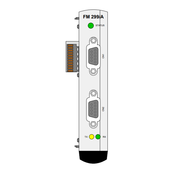
The FM 299/A module is a K2-200 field bus master module for the Sanyo Denki drive bus. FM 299/A STATUS Front view FM 299/A module Two FM 299/A modules can be operated on one control CPU. Project Engineering Manual, version: 1.1 / article no.: 1000296 © KEBA 2006... -
Page 8: General Safety Instructions
Turn off the power supply before inserting or removing the module. Otherwise, the module can be destroyed or undefined signal states can lead to damage of the control system. Project Engineering Manual, version: 1.1 / article no.: 1000296 © KEBA 2006... -
Page 9: Configuration
Once all modules have been specified in the system and after all parameters have been adjusted the Kemro.manager creates the necessary cfg-files. Project Engineering Manual, version: 1.1 / article no.: 1000296 © KEBA 2006... -
Page 10: Creation Of Cfg-File
= 10 periodDenom = 200 traceWord = -1 [IO.ONBOARD.KBUS:0.FM299:0.GA1060B:0.QSE:0.BANK1] DAT2 = 16#0001 DAT3 = 16#0001 DAT4 = 16#0005 DAT5 = 16#0000 DAT6 = 16#0032 DAT7 = 16#0090 Project Engineering Manual, version: 1.1 / article no.: 1000296 © KEBA 2006... -
Page 11: Setting The K-Bus Address
The K-Bus plug is located underneath the upper cover. ADR0 ADR1 Position of the address switch On leaving the factory the FM 299/A module is set to address 0 and both covers are closed. Project Engineering Manual, version: 1.1 / article no.: 1000296 © KEBA 2006... -
Page 12: Connections, Wiring
A multi-core twisted cable can also be used. Attention must be paid that the GA1060 Bus+ and the GA1060 bus-lines are guided in a common twisted pair of wires. Project Engineering Manual, version: 1.1 / article no.: 1000296 © KEBA 2006... -
Page 13: Cable Routing
The total bus length must not exceed 10 meters, whereby the gaps between the individual participants can be freely selected. Drive controls FM 299/A STATUS Drive controls FM 299/A STATUS Drive controls BT … bus terminating board Project Engineering Manual, version: 1.1 / article no.: 1000296 © KEBA 2006... -
Page 14: Schematic Diagram Of The Bus Topology Bus Terminating Board
120 Ω in between the Pins 1 and 2 (GA1060 Bus). 120 Ω GA1060 Bus+ GA1060 Bus- n.c. GA1060-Bus interface with activated bus terminating board Project Engineering Manual, version: 1.1 / article no.: 1000296 © KEBA 2006... -
Page 15: Operation And Displays
After switch-on -> module faulty In cyclical mode -> Communication error, no communication possible GA1060 Bus Status LEDs LED color Labeling Function yellow Indicates transmission activity green Indicates receiving activity Project Engineering Manual, version: 1.1 / article no.: 1000296 © KEBA 2006... -
Page 16: Technical Data
130 g Standards: The module conforms to the following standards: General information UL 508 UL – listed Product standard for programmable controllers: IEC 61131-1:2003 General information IEC 61131-2:2003 Hardware Project Engineering Manual, version: 1.1 / article no.: 1000296 © KEBA 2006...
Need help?
Do you have a question about the Kemro K2 and is the answer not in the manual?
Questions and answers