
Related Manuals for Kramer FC-18


Summary of Contents for Kramer FC-18
- Page 1 USER MANUAL MODEL: FC-18 Display Controller P/N: 2900-301044 Rev 1 www.kramerAV.com...
-
Page 2: Table Of Contents
Typical Applications Defining FC-18 Display Controller Mounting FC-18 Connecting FC-18 Connecting Remote Control Switches Connecting to FC-18 via RS-232 Connecting to FC-18 via Ethernet Controlling the FC-18 Controlling the Display via FC-18 Controlling the Display via HDMI OUT Port (CEC) -
Page 3: Introduction
Kramer Electronics Ltd. Introduction Welcome to Kramer Electronics! Since 1981, Kramer Electronics has been providing a world of unique, creative, and affordable solutions to the vast range of problems that confront the video, audio, presentation, and broadcasting professional on a daily basis. In recent years, we... -
Page 4: Overview
European Advanced Recycling Network (EARN) and will cover any costs of treatment, recycling and recovery of waste Kramer Electronics branded equipment on arrival at the EARN facility. For details of Kramer’s recycling arrangements in your particular country go to our recycling pages at www.kramerav.com/support/recycling. -
Page 5: Typical Applications
3 units in a 1U rack space with the recommended rack adapter. FC-18 supports CEC functionality and has been tested and verified with many display models. Kramer cannot guarantee CEC compatibility with all CEC displays due to command variations and proprietary commands implemented by some manufacturers in some of their displays. -
Page 6: Defining Fc-18 Display Controller
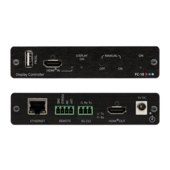
Kramer Electronics Ltd. Defining FC-18 Display Controller This section defines FC-18. Figure 1: FC-18 Display Controller Front Panel Feature Function PROG USB Connector Connect to update the firmware. HDMI™ IN Connector Connect to an HDMI source. Lights green when a valid HDMI signal is detected. Detection is based on the presence of 5V and a clock signal on the HDMI input. - Page 7 Kramer Electronics Ltd. Figure 2: FC-18 Display Controller Rear Panel Feature Function Ethernet RJ-45 Port Connect to a PC via a LAN to control the device, send commands to the display, or tunnel RS-232 data to the display. Also use for firmware upgrade.
-
Page 8: Mounting
Kramer Electronics Ltd. Mounting FC-18 This section provides instructions for mounting FC-18. Before installing, verify that the environment is within the recommended range: • Operation temperature – 0 to 40C (32 to 104F). • Storage temperature – -40 to +70C (-40 to +158F). -
Page 9: Connecting
Kramer Electronics Ltd. Connecting FC-18 Always switch off the power to each device before connecting it to your FC-18. After connecting your FC-18, connect its power and then switch on the power to each device. Figure 3: Connecting to FC-18... -
Page 10: Connecting Remote Control Switches
(i.e., constant contact connection rather than momentary connection), allowing, for example, connection to an occupancy sensor that triggers the toggle commands. Connecting to FC-18 via RS-232 You can connect to the FC-18 via an RS-232 connection using, for example, a PC. -
Page 11: Connecting To Fc-18 Via Ethernet
FC-18 with the factory configured default IP address. Press the front panel ON and OFF buttons simultaneously to show the current device IP address on the display connected to the HDMI output of the FC-18. After connecting the FC-18 to the Ethernet port, configure your PC as follows: 1. - Page 12 (TCP/IPv4) depending on the requirements of your IT system. 5. Click Properties. The Internet Protocol Properties window relevant to your IT system appears as shown in Figure 5 Figure Figure 5: Internet Protocol Version 4 Properties Window FC-18 – Connecting FC-18...
- Page 13 Ethernet port on a network hub or using a straight-through cable with RJ-45 connectors. Configuring the Ethernet Port You can set the Ethernet parameters via the embedded webpages (see Using the Embedded Web Pages on page 36). FC-18 – Connecting FC-18...
-
Page 14: Controlling The
Using the Embedded Web Pages on page 36). Control FC-18 by connecting a laptop or controller to the RS-232 port. Figure 8: Controlling FC-18 via RS-232 Port To control the device: 1. Connect a controller to the FC-18 RS-232 port to control the device. -
Page 15: Controlling The Display Via
To control the display via FC-18: 1. Choose the FC-18 connection to the display. 2. Choose the user control method via FC-18. 3. Wire and configure the system according to the appropriate configuration in the table below: FC-18 Controls Display Using... -
Page 16: Controlling The Display Via Hdmi Out Port (Cec)
• Controlling Via Ethernet (FC-18 Sends CEC to HDMI OUT) on page 16. • Controlling Via Front Panel Buttons (FC-18 Sends CEC to HDMI OUT) on page 16. • Controlling Via REMOTE ON/OFF Pins (FC-18 Sends CEC to HDMI OUT) on page 17. - Page 17 Kramer Electronics Ltd. Figure 10: RS-232 & Remote Page 3. Check Port Definition to FC-18 Control. Figure 11: RS-232 & Remote Page – RS-232 Controls FC-18 4. Send the CEC protocol command to control the display (see Protocol 3000 Commands on page 63).
- Page 18 Protocol 3000 Commands on page 63). The display is controlled by Ethernet via the HDMI port. Controlling Via Front Panel Buttons (FC-18 Sends CEC to HDMI OUT) You can turn the display on or off using the front panel buttons.
- Page 19 For further details, see Configuring CEC Commands on page 50. Controlling Via REMOTE ON/OFF Pins (FC-18 Sends CEC to HDMI OUT) You can turn the display on or off via the contact closure REMOTE ON and OFF pins or TOGGLE pin.
- Page 20 For further details, see Configuring CEC Commands on page 50. Controlling Via REMOTE TOGGLE Pin (FC-18 Sends CEC to HDMI OUT) You can turn the display on or off via the REMOTE contact closure TOGGLE pin that is connected, for example, to an occupancy sensor.
- Page 21 CEC OFF command (\xe06). When the unit detects that the HDMI signal (clock) returns, it turns the display on by sending the CEC ON command (\xe0\x04). FC-18 – Controlling the Display via FC-18...
- Page 22 2. In the Navigation pane, click Video & Audio. The Video & Audio page appears. Figure 21: Video & Audio Page – Setting 5V Off Signal-Loss Delay Time 3. Enter the 5V powering off delay time and click Set. FC-18 – Controlling the Display via FC-18...
-
Page 23: Controlling The Display Via Its Rs-232 Port
• Controlling the Display using Ethernet (Sending to the Display’s RS-232 Port) on page 22. • Controlling the Display via FC-18’s Front Panel Buttons (Sending to the Display’s RS- 232 Port) on page 23. • Controlling the Display via FC-18’s REMOTE ON/OFF Pins (Sending to the Display’s RS-232 Port) on page 24. - Page 24 4. Under Settings, enter the communication settings of the connected display. 5. Send display commands via Ethernet through the RS-232 port to the display. The display RS-232 commands are tunneled from the Ethernet to the display via the RS-232 port. FC-18 – Controlling the Display via FC-18...
- Page 25 Kramer Electronics Ltd. Controlling the Display via FC-18’s Front Panel Buttons (Sending to the Display’s RS-232 Port) You can control a display via the FC-18 RS-232 port using the front panel buttons. To control the display using the ON/OFF buttons via RS-232 port: 1.
- Page 26 5. Press ON/OFF on the front panel to turn the display on or off. The display is controlled via ON and OFF buttons on the front panel. Controlling the Display via FC-18’s REMOTE ON/OFF Pins (Sending to the Display’s RS-232 Port)
- Page 27 5. Check Enable next to the Button On and Button Off commands, and click Add. 6. Press ON/OFF on the front panel to turn the display on or off. The display is controlled via ON and OFF buttons on the front panel via RS-232. FC-18 – Controlling the Display via FC-18...
- Page 28 Kramer Electronics Ltd. Controlling the Display via FC-18’s REMOTE TOGGLE Pin (Sending to the Display’s RS-232 Port) You can turn the display on or off via the contact closure TOGGLE pin that is connected, for example, to an occupancy sensor.
- Page 29 2. In the Navigation pane, click Video & Audio. The Video & Audio page appears. Figure 35: Video & Audio Page – Setting 5V Off Signal-Loss Delay Time 3. Enter the 5V powering off delay time and click Set. FC-18 – Controlling the Display via FC-18...
-
Page 30: Controlling The Display Via The Network (Ethernet)
• Controlling Via Ethernet (FC-18 Sends CEC to HDMI OUT) on page 16. • Controlling Via Front Panel Buttons (FC-18 Sends CEC to HDMI OUT) on page 16. • Controlling Via REMOTE ON/OFF Pins (FC-18 Sends CEC to HDMI OUT) on page 17. - Page 31 Display) You can send a CEC command to the display via the network by connecting a laptop or controller to the Ethernet port on FC-18. To control the display by Ethernet via the Network: 1. Connect a controller to the...
- Page 32 8. Press ON/OFF on the front panel to turn the display on or off. The display is controlled via ON and OFF buttons on the front panel. For further details, see Controlling an External Device via Ethernet on page 52. FC-18 – Controlling the Display via FC-18...
- Page 33 (see Setting the Toggle Pin Function on page 45). 2. In the Navigation pane, click Ethernet. The Ethernet page appears. Figure 42: Ethernet Page – Remote On and Remote Off Command Configuration FC-18 – Controlling the Display via FC-18...
- Page 34 Ethernet port and HDMI port to the Ethernet-controlled display. Figure 44: Sending Occupancy-Sensor Triggered Commands via Ethernet Port 2. In the Navigation page, click RS-232 & Remote. The RS-232 & Remote page appears. FC-18 – Controlling the Display via FC-18...
- Page 35 8. Click TCP or UDP to select the protocol mode. 9. Configure the Toggle On and Toggle Off commands. 10. Check Enable next to the Toggle On and Toggle Off commands, and click Add. FC-18 – Controlling the Display via FC-18...
- Page 36 2. In the Navigation pane, click Video & Audio. The Video & Audio page appears. Figure 49: Video & Audio Page – Setting 5V Off Signal-Loss Delay Time 3. Enter the 5V powering off delay time and click Set. FC-18 – Controlling the Display via FC-18...
- Page 37 10. If required, configure the other commands, and add them to the Ethernet command list. The display is triggered to turn on and off automatically via 5V/No 5V/Clock/No Clock commands via the Ethernet port. For further details, see Controlling an External Device via Ethernet on page 52. FC-18 – Controlling the Display via FC-18...
-
Page 38: Using The Embedded Web Pages
Kramer Electronics Ltd. Using the Embedded Web Pages Use the embedded web pages to configure and control FC-18. The web pages are accessed using a Web browser and an Ethernet connection. Before attempting to connect: • Perform the procedures in (see Connecting to FC-18 via Ethernet on page 9). - Page 39 Configuring CEC Commands on page 50. • Controlling an External Device via Ethernet on page 52. • Setting Web Page Access Permission on page 54. • Viewing About Us Page on page 56. FC-18 – Using the Embedded Web Pages...
-
Page 40: Viewing General Information
Changing Device Settings Use the Device Settings page to perform the following operations: • Changing the Network Settings on page 39. • Upgrading the Firmware on page 40. • Soft Factory Reset on page 41. FC-18 – Using the Embedded Web Pages... - Page 41 Static IP Address is the actual IP address when operating in non-DHCP mode and is also the fallback IP address, auto-acquired after no DHCP server detection. Default is set to 192.168.1.39. 3. Click Set. The confirmation window appears: Figure 56: Device Settings Page – Changing to DHCP Mode FC-18 – Using the Embedded Web Pages...
- Page 42 2. Click Choose File next to Firmware Update. An Open window appears. 3. Select the correct firmware file. 4. Click Open. The selected file appears next to Firmware Update. Figure 58: Device Settings Page – Firmware File Uploaded FC-18 – Using the Embedded Web Pages...
- Page 43 3. Click OK and wait for the web page to reload following soft factory reset. Default Communication Parameters on page to view other factory reset procedures. Device is reset to its factory default parameters, excluding network parameters. FC-18 – Using the Embedded Web Pages...
-
Page 44: Defining Video And Audio Settings
To set video and audio parameters: 1. In the Navigation pane, click Video & Audio. The Video & Audio settings page appears. Figure 62: FC-18 Video & Audio Page 2. Set 5V power-off delay time upon signal loss and click Set. -
Page 45: Managing Edid
Kramer Electronics Ltd. Managing EDID Read the EDID from the output, from the default or from a custom file to the FC-18. You can read the EDID only when EDID mode is set to User (see Defining Video and Audio Settings on page 42). - Page 46 2. In the File area, click Choose a file to browse for the custom EDID file location. 3. Open the custom EDID file. 4. Click Copy and follow the instructions on-screen. The custom EDID is copied to the input. FC-18 – Using the Embedded Web Pages...
-
Page 47: Setting Rs-232 Port And Toggle Remote Switch Functions
Kramer Electronics Ltd. Setting RS-232 Port and Toggle Remote Switch Functions Define the function of the RS-232 port and the TOGGLE remote switch on the FC-18, using the RS-232 & Remote page. Setting the Toggle Pin Function To set the Toggle pin function: 1. - Page 48 2. Check RS-232 port function from the Port Definition list: ▪ FC-18 Control – The RS-232 port is connected to an external controller and is configured to control the FC-18. It accepts RS-232 commands to control the unit (for example, instructing it to send a CEC command to send “turn the display on or off), Controlling FC-18 via RS-232 on page 47).
- Page 49 Kramer Electronics Ltd. Controlling FC-18 via RS-232 Control FC-18 by connecting a laptop or controller to the RS-232 port. Figure 69: Controlling FC-18 via RS-232 Port To control the device: 1. Connect a controller to the FC-18 RS-232 port to control the device.
- Page 50 5V, No 5V, Button On, Button Off, Remote On, Remote Off, Toggle On or Toggle Off). ▪ Enter a delay time, if required. ▪ Check Hex for command Hex format, if required. ▪ Check Enable to enable the command. Figure 71: RS-232 – Creating a Command FC-18 – Using the Embedded Web Pages...
- Page 51 1. In the Navigation pane, click RS-232 & Remote. The RS-232 & Remote page appears. 2. Check Ethernet Tunneling. Figure 73: RS-232 Page – Tunneling via Ethernet 3. Enter the display communication settings (to enable communication with the display). FC-18 – Using the Embedded Web Pages...
-
Page 52: Configuring Cec Commands
1. In the Navigation pane select CEC. The CEC Configuration page appears. Figure 74: CEC Configuration Page 2. Enable (default) or Disable CEC control. 3. Enter the CEC logical address (14, by default) and click Set. FC-18 – Using the Embedded Web Pages... - Page 53 Click Test to test the command. ▪ Change any of the command configurations. ▪ Enable or disable the command. The display ON/OFF commands are listed by default. CEC commands are sent to the display via the HDMI port. FC-18 – Using the Embedded Web Pages...
-
Page 54: Controlling An External Device Via Ethernet
5V, No 5V, Button On, Button Off, Remote On, Remote Off, Toggle On or Toggle Off). ▪ Enter a delay time, if required. ▪ Check Hex for command Hex format, if required. ▪ Check Enable to enable the command. Figure 78: Configuring an External Device Command FC-18 – Using the Embedded Web Pages... - Page 55 10. Repeat the previous steps to add any other commands to the command list: Figure 80: Ethernet Page – Unmute Display Command Added The enabled command is sent to the display via the Ethernet. FC-18 – Using the Embedded Web Pages...
-
Page 56: Setting Web Page Access Permission
This section describes how to change the password and disable/enable access permission. To change the password: 1. In the Navigation pane, click Security. The Security page appears. Figure 81: Security Page 2. Enter the new password. FC-18 – Using the Embedded Web Pages... - Page 57 2. Uncheck Authenticate Web pages Access. Current credentials are grayed out. 3. Click Set changes The following message appears: Figure 84: Security – Security Disable Confirmation 4. Click OK. Authentication is not required. FC-18 – Using the Embedded Web Pages...
-
Page 58: Viewing About Us Page
4. Click OK. appears, and authentication is now required. Viewing About Us Page In the Navigation pane, click About to view the FC-18 webpage version and Kramer Electronics Ltd details. Figure 86: About Us Page FC-18 – Using the Embedded Web Pages... -
Page 59: Firmware Upgrade
40) or by connecting a memory stick to the PROG USB port To upgrade the firmware via a memory stick: 1. Save the new firmware file to an empty memory stick. 2. Connect power to FC-18. 3. Plug the memory stick into the PROG USB port on the FC-18 front panel. -
Page 60: Technical Specifications
Screen size....360 x 290 mm (18.2 in) Power management..Standby, Suspend, Active off/sleep Extension blocs..1 (CEA-EXT) ------------------------- DDC/CI....n/a Color characteristics Default color space..Non-sRGB Display gamma.... 2.40 Red chromaticity..Rx 0.611 - Ry 0.329 FC-18 – Technical Specifications... - Page 61 NB: NTSC refresh rate = (Hz*1000)/1001 CE audio data (formats supported) LPCM 2-channel, 16/20/24 bit depths at 32/44/48 kHz CE speaker allocation data Channel configuration..2.0 Front left/right..Yes Front LFE....No Front center..... No Rear left/right..No FC-18 – Technical Specifications...
- Page 62 CEC physical address..1.0.0.0 Maximum TMDS clock..165MHz Report information Date generated... 05/03/2020 Software revision..2.60.0.972 Data source....File - NB: improperly installed Operating system..6.2.9200.2 Raw data 00,FF,FF,FF,FF,FF,FF,00,2D,B2,1D,03,31,00,00,00,13,1A,01,03,80,24,1D,8C,EA,9C,20,9C,54,4F,8F,26, 21,52,56,2F,CF,00,A9,40,81,80,90,40,D1,C0,31,59,45,59,61,59,81,99,02,3A,80,18,71,38,2D,40,58,2C, 45,00,10,09,00,00,00,1E,9E,20,00,90,51,20,1F,30,48,80,36,00,10,0A,00,00,00,1C,00,00,00,FC,00,46, 43,2D,31,38,0A,20,20,20,20,20,20,20,00,00,00,FD,00,17,55,1B,5B,11,00,0A,20,20,20,20,20,20,01,C4, 02,03,20,F3,4D,90,1F,04,13,05,14,02,11,06,15,22,21,20,23,09,07,07,83,01,00,00,65,03,0C,00,10,00, 9A,29,A0,D0,51,84,22,30,50,98,36,00,10,0A,00,00,00,1C,66,21,56,AA,51,00,1E,30,46,8F,33,00,10,09, 00,00,00,1E,28,3C,80,A0,70,B0,23,40,30,20,36,00,10,0A,00,00,00,1A,30,2A,40,C8,60,84,64,30,18,50, 13,00,10,09,00,00,00,1E,21,39,90,30,62,1A,27,40,68,B0,36,00,10,0A,00,00,00,1C,00,00,00,00,00,08 FC-18 – Technical Specifications...
-
Page 63: Default Communication Parameters
TCP Port #: 5001 UDP Port #: 50001 Factory Reset Embedded web pages Go to: Device Settings-> Soft factory reset Full Factory Reset Press and hold OFF button for 3 seconds. Protocol 3000 #FACTORY<CR> Security Security User/Password admin/admin FC-18 – Technical Specifications... -
Page 64: Protocol 3000
(<…>) and must be separated by a period (.). The command framing varies according to how you interface with the FC-18. The following figure displays how the # command is framed using terminal communication software (such as Hercules): FC-18 –... -
Page 65: Protocol 3000 Commands
FEEDBACK ~nn@ECHOstatus<CR><LF> – TCP/UDP portType ETH-PORT Set Ethernet port protocol. COMMAND Set the Ethernet port protocol 0 – TCP #ETH-PORTportType,ETHPort<CR> for TCP to port 12457: 1 – UDP #ETH-PORT0,12457<CR> FEEDBACK ETHPort – TCP/UDP port number ~nn@ETH-PORTportType,ETHPort<CR><LF> FC-18 – Protocol 3000... - Page 66 Length (data length + 2 for CRC) – (2 bytes in length) Data (data length -2 bytes) CRC – 2 bytes Packet ID Length Data Response: ~nnnnok<CR><LF> (Where NNNN is the received packet ID in ASCII hex digits.) FC-18 – Protocol 3000...
- Page 67 Set the IP address to #NET-IPip_address<CR> 192.168.1.39: xxx.xxx.xxx.xxx For proper settings #NET- FEEDBACK consult your network IP192.168.001.039<CR> ~nn@NET-IPip_address<CR><LF> administrator. – Format: ip_address NET-IP? Get IP address. COMMAND Get the IP address: #NET-IP?<CR> #NET-IP?<CR> xxx.xxx.xxx.xxx FEEDBACK ~nn@NET-IPip_address<CR><LF> FC-18 – Protocol 3000...
- Page 68 Disable the video on the flag – Video Mute on output. #VMUTEoutput_id,flag<CR> output: 0 – Video enabled #VMUTE1,1<CR> FEEDBACK Video mute parameter 1 – Video disabled ~nn@VMUTEoutput_id,flag<CR><LF> 2 (blank picture) is not 2 – Blank picture supported. FC-18 – Protocol 3000...
- Page 69 VMUTE? Get video on output COMMAND status. #VMUTE?output_id_<CR> outputs flag – Video Mute FEEDBACK Video mute parameter 0 – Video enabled ~nn@VMUTEoutput_id,flag<CR><LF> 2 (blank picture) is not 1 – Video disabled supported. 2 – Blank picture FC-18 – Protocol 3000...
-
Page 70: Result And Error Codes
(Reserved) ERR_RESERVED_8 (Reserved) ERR_RESERVED_9 (Reserved) ERR_RESERVED_10 (Reserved) ERR_RESERVED_11 (Reserved) ERR_RESERVED_12 (Reserved) ERR_EDID_CORRUPTED EDID corrupted ERR_NON_LISTED Device specific errors File has the same CRC – no changed ERR_SAME_CRC ERR_WRONG_MODE Wrong operation mode ERR_NOT_CONFIGURED Device/chip was not initialized FC-18 – Protocol 3000... - Page 71 Kramer Electronics will not be responsible for any costs related to the removal or re- installation of this product from or into any installation. Kramer Electronics will not be responsible for any costs relat ed to any setting up this product, any adjustment of user controls or any programming required for a specific installation of this product.
- Page 72 SAFETY WARNING Disconnect the unit from the power supply before opening and servicing For the latest information on our products and a list of Kramer distributors, visit our website where updates to this user manual may be found. We welcome your questions, comments, and feedback.
Need help?
Do you have a question about the FC-18 and is the answer not in the manual?
Questions and answers