Kramer FC-28 User Manual
Hide thumbs
Also See for FC-28:
- User manual (68 pages) ,
- User manual (79 pages) ,
- Quick start manual (2 pages)

Related Manuals for Kramer FC-28


Summary of Contents for Kramer FC-28
- Page 1 USER MANUAL MODEL: FC-28 Ethernet Controller P/N: 2900-300539 Rev 5 www.kramerAV.com...
-
Page 2: Table Of Contents
Getting Started Overview Typical Applications Defining FC-28 Ethernet Controller Initial Configuration and Use Overview Configuring the FC-28 Ethernet Controller Configuring a Virtual Port on the PC Setting Up an Ethernet Connection on the PC Mounting FC-28 Connecting FC-28 Connecting via Ethernet... -
Page 3: Introduction
Kramer Electronics Ltd. Introduction Welcome to Kramer Electronics! Since 1981, Kramer Electronics has been providing a world of unique, creative, and affordable solutions to the vast range of problems that confront the video, audio, presentation, and broadcasting professional on a daily basis. In recent years, we... -
Page 4: Overview
European Advanced Recycling Network (EARN) and will cover any costs of treatment, recycling and recovery of waste Kramer Electronics branded equipment on arrival at the EARN facility. For details of Kramer’s recycling arrangements in your particular country go to our recycling pages at www.kramerav.com/support/recycling. - Page 5 Figure 1: FC-28 Controlling Devices Remotely Using K-Touch 3.0 over a LAN Flexible Connectivity • Network connectivity that lets you connect a Kramer (or other) device via its control I/O port to an Ethernet LAN. • Working in conjunction with K-Touch 3 for remote control of devices over an Ethernet...
-
Page 6: Typical Applications
LAN Configurator software to discover devices that are attached to the network, including the FC-28. FC-28 includes the Virtual Serial Port Manager (Kramer VSPM) for compatibility with applications based on COM-port communication. Virtual Serial Port Manager: • ® Makes the... -
Page 7: Defining Fc-28 Ethernet Controller
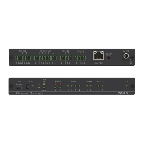
Kramer Electronics Ltd. Defining FC-28 Ethernet Controller Front Panel Figure 2 defines the front panel of the FC-28. Figure 2: FC-28 Ethernet Controller Front Panel Feature Function F/W UPGRADE Mini USB Connect to a PC to perform a firmware upgrade. - Page 8 Kramer Electronics Ltd. Rear Panel Figure 3 defines the rear panel of the FC-28. Figure 3: FC-28 Ethernet Controller Rear Panel Feature Function Connect to the first RS-232 controlled device. RS-232 Two 3-pin Terminal Blocks Connect to the second RS-232 controlled device.
-
Page 9: Initial Configuration And Use Overview
Configuring a Virtual Port on the PC on page 9). • Configuring an Ethernet connection on the PC (see Setting Up an Ethernet Connection on the PC on page 9). Figure 4: Connecting the FC-28 for Initial Configuration FC-28 – Initial Configuration and Use Overview... -
Page 10: Configuring The Fc-28 Ethernet Controller
IP address has been automatically assigned to the FC-28. This can be done by using K-LAN Configurator to discover the IP address of the FC-28. This is available for download from our website at www.kramerav.com. To browse the FC-28... -
Page 11: Configuring A Virtual Port On The Pc
Configuring a Virtual Port on the PC If the control application cannot work with an Ethernet driver, download the Kramer VSPM from our Web site to set a virtual port for each local port on your FC-28. The Kramer VSPM software lets you emulate virtual ports which normally would be present in the machine hardware. -
Page 12: Mounting
Kramer Electronics Ltd. Mounting FC-28 This section provides instructions for mounting FC-28. Before installing, verify that the environment is within the recommended range: • Operation temperature – 0 to 40C (32 to 104F). • Storage temperature – -40 to +70C (-40 to +158F). - Page 13 Kramer Electronics Ltd. Connecting FC-28 Always switch off the power to each device before connecting it to your FC-28. After connecting your FC-28, connect its power and then switch on the power to each device. Figure 6: Connecting the FC-28 Ethernet Controller...
-
Page 14: Connecting
3. Highlight the network adapter you want to use to connect to the device and click Change settings of this connection. The Local Area Connection Properties window for the selected network adapter appears as shown in Figure Figure 7: Local Area Connection Properties Window FC-28 – Connecting FC-28... - Page 15 Figure 8: Internet Protocol Version 4 Properties Window Figure 9: Internet Protocol Version 6 Properties Window 5. Select Use the following IP Address for static IP addressing and fill in the details as shown in Figure FC-28 – Connecting FC-28...
- Page 16 You can connect the Ethernet port of the FC-28 to the Ethernet port on a network hub or using a straight-through cable with RJ-45 connectors. Connecting to FC-28 via RS-232 or IR To connect to the FC-28 via RS-232: •...
- Page 17 Kramer Electronics Ltd. Connecting the GP I/O Ports on the FC-28 to a Device To connect the GP I/O port on the FC-28 to a device: • Connect the G pin on the GP I/O port to the ground connection on the device.
-
Page 18: Remote Operation Via The Web Pages
The Loading page appears followed shortly by the General Info page shown in Figure The General Info page displays the following: • Model name. • Firmware version. • Device serial number. • Web page version. FC-28 – Remote Operation via the Web Pages... - Page 19 3. Browse to the required location to which to save the file. 4. Enter the required name for the saved preset. 5. Click OK. The current configuration is saved. When using Chrome, the file is automatically saved in the Downloads folder. FC-28 – Remote Operation via the Web Pages...
-
Page 20: Connected Clients Page
Use a time server to set the time and date automatically (if the device is connected to the Internet), including the Time Zone and daylight savings time. Figure 13: Device Settings Page FC-28 – Remote Operation via the Web Pages... - Page 21 2. Click the Use Time Server ON button. 3. Enter the IP address of the Time Server. 4. Enter the hour of the day at which the FC-28 should synchronize with the Time Server. 5. Click Save Changes. FC-28 – Remote Operation via the Web Pages...
-
Page 22: Communication Page
Edit the IP settings for static IP addressing. The default IP address setting for the device is DHCP on. Figure 14: Communication Page After modifying the IP address, Mask, or Gateway, click Set to save the changes. FC-28 – Remote Operation via the Web Pages... -
Page 23: Serial Port Settings Page
▪ Stop bits. • Select whether or not to send replies on the port to the new client, (see also Connected Clients Page on page 18). Figure 15: Serial Port Settings Page FC-28 – Remote Operation via the Web Pages... -
Page 24: Gpio Port Settings Page
(connecting one terminal of the switch to ground, and the other to the input) or for an alarm closing a circuit that activates a series of actions. FC-28 – Remote Operation via the Web Pages... - Page 25 Take care that the current in this configuration does not exceed 100mA! • When disabled, the port state is high. For the state to be low, you must click Low from the Current Status. FC-28 – Remote Operation via the Web Pages...
- Page 26 LEDs. The voltage output is TTL positive logic: open: ~ 3.5V; closed: ~ 0.3V. • When enabled, the port state is low and to set it high, you must click High from the Current Status. FC-28 – Remote Operation via the Web Pages...
- Page 27 1 and with a maximum of 100. The voltage of each step is dependent on the number of steps selected: Individual step voltage = 30V / number of steps. When selecting the Analog In trigger type, the Pullup resistor and Threshold settings are disabled. FC-28 – Remote Operation via the Web Pages...
-
Page 28: Relay Port Settings Page
The current relay status is shown to the right of the button. 2. Click Close. The relay closes, the button changes color, and the Relay 2 LED on the front panel lights green. FC-28 – Remote Operation via the Web Pages... -
Page 29: Ir Command Learner Page
Press Clear to erase the current command that has been learned. Press Copy to copy the current command to the clipboard Load/Save Buttons Press Load to retrieve a previously saved command. Press Save to save the current command FC-28 – Remote Operation via the Web Pages... -
Page 30: Security Page
Figure 24: Authentication Required Popup 3. Enter the default username and password. 4. Click OK. 5. Wait until the Web pages have reloaded. Click the Security page button. The page show in Figure 25 is displayed. FC-28 – Remote Operation via the Web Pages... -
Page 31: Logs Page
The display may not update automatically. Click Refresh to update the display. Use the Log Filter check-boxes to select which events to display from the log. Use the Log Config check-boxes to select which events are recorded. FC-28 – Remote Operation via the Web Pages... -
Page 32: About Us Page
Kramer Electronics Ltd. About Us Page The About Us page displays the Web page version and the Kramer company details. Figure 27: About Us Page FC-28 – Remote Operation via the Web Pages... -
Page 33: Configuring And Maintaining
The relevant IR Out LED lights, the device is not available for normal operation, and the FC-28 sends an IR Learning start message to all connected clients. 2. Using the IR remote control, send the required command to the FC-28. FC-28 processes the IR signal and generates the Pronto code. -
Page 34: Upgrading Firmware
Kramer Electronics Ltd. Upgrading Firmware Use the Kramer K-UPLOAD software to upgrade the firmware. The latest version of K-UPLOAD and installation instructions can be downloaded from our website at: www.kramerav.com/support/product_downloads.asp. FC-28 – Configuring and Maintaining FC-28... -
Page 35: Technical Specifications
Power adapter 5V DC 2A IR Cable C-A35M/IRE-10 OPTIONS: Recommended Rack Adapter (see www.kramerav.com/product/FC-28) IR Cables—C-A35M/2IRE-10, C-A35M/IRR-3, C-AS35M/AS35F-50, CA35M/IRE-10 Bulk cable for serial, GP I/O, or relay control—BC-1T-300M Specifications are subject to change without notice at www.kramerav.com FC-28 – Technical Specifications... -
Page 36: Data Handling Performance
90 TCP and 70 UDP ports. You can therefore connect up to 45 devices to the FC-28 using TCP. As UDP connections require only a single port per device, you can connect up to 70 devices using UDP. FC-28 – Technical Specifications... -
Page 37: Default Communication Parameters
Subnet Mask: 255.255.0.0 Gateway: 192.168.0.1 Maximum Simultaneous Connections: Device TCP Port: 5000 TCP Serial Port 1: 5001 TCP Serial Port 2: 5002 UDP Port: 50000 Default Logon Authentication Web Page Access User name: Admin Password: Admin FC-28 – Default Communication Parameters... -
Page 38: Kramer Protocol 3000
Kramer Electronics Ltd. Kramer Protocol 3000 FC-28 can be operated using serial commands from a PC, remote controller or touch screen using the Kramer Protocol 3000. This section describes: Understanding Protocol 3000 Command Format Start Address (optional) Body Delimiter Destination_id@... - Page 39 Message starting character '#' – For host command/query '~' – For device response Device address (Optional, for K-NET) K-NET Device ID followed by '@' Query sign '?' follows some commands to define a query request. FC-28 – Kramer Protocol 3000...
- Page 40 Kramer device. To enter CR press the Enter key. ( LF is also sent but is ignored by command parser). For commands sent from some non-Kramer controllers like Crestron, some characters require special coding (such as, /X##). Refer to the controller manual.
-
Page 41: Kramer Protocol 3000 - Command List
Kramer Electronics Ltd. Kramer Protocol 3000 – Command List Command Description Protocol handshaking BUILD-DATE? Read device build date COM-ROUTE Set/get tunneling port routing COM-ROUTE-ADD Add communication route tunnel connection COM-ROUTE-REMOVE Remove communication route tunnel connection List files ETH-PORT Sets protocol port... -
Page 42: Kramer Protocol 3000 - Detailed Commands
Kramer Electronics Ltd. Kramer Protocol 3000 – Detailed Commands This section lists the detailed commands applicable to the FC-28. Command Name Permission Transparency Set: End User Public Get: Description Syntax Set: Protocol handshaking #␍ Get: Response ~nn@␠OK␍␊ Parameters Response triggers... - Page 43 ETH_rep_en - 1 - COM port sends replies to new clients. 0 - COM port does not send replies to new clients Timeout - Keep alive timeout in seconds (1 to 360) Response Triggers Notes FC-28 – Kramer Protocol 3000...
- Page 44 - file size in bytes. A file can take more space on device memory file_id - internal ID for file in file system free_size - free space in bytes in device file system Response Triggers Notes FC-28 – Kramer Protocol 3000...
- Page 45 EthRepEn – 1 = COM port sends replies to new clients. 0 = COM port does not send replies to new clients Wired – 1 = wired connection, 0 = not wired connection Response Triggers Notes FC-28 – Kramer Protocol 3000...
- Page 46 Command Name Permission Transparency Set: Get: FS-FREE? Administrator Public Description Syntax Set: #FS-FREE?␍ Get: Get file system free space Response ~nn@FS_FREE␠free_size␍␊ Parameters free_size - free size in device file system in bytes Response Triggers Notes FC-28 – Kramer Protocol 3000...
- Page 47 Get HW GPIO configuration Response ~ nn@GPIO-CFG␠HwGpioNum,HwGpioType,HwGpioDir␍␊ Parameters HwGpioNum – HW GPIO number (1-2) HwGpioType – HW GPIO type (0=Analog, 1=Digital) – HW GPIO direction (0=Input, 1=Output) HwGpioDir – enable/disable pull-up (0=Disable, 1=Enable) Pullup Response Triggers Notes FC-28 – Kramer Protocol 3000...
- Page 48 CurrentStep – the actual step depending on the measured voltage Response Triggers Notes In digital mode the answer is 2 In analog mode the answer is 1 to 100 In other modes and error is returned FC-28 – Kramer Protocol 3000...
- Page 49 Get HW GPIO voltage levels GPIO-VOLT?␠ HwGpioNumber␍ Response ~nn @GPIO-VOLT␠HwGpioNumber,Voltage␍␊ Parameters HwGpioNum – HW GPIO number 1-2 Voltage – voltage 0 to 30000 millivolts Response Triggers Notes This command is not available in digital out mode FC-28 – Kramer Protocol 3000...
- Page 50 CommandName – String: IR command name limited to 15 chars. Controlling device must send the correct name (whitespace or commas forbidden) Timeout - Timeout in seconds (1 to 60) IR_Status - (see IR Status on page 61) Response Triggers Notes FC-28 – Kramer Protocol 3000...
- Page 51 In each device, some connections can be logged in to different levels and some do not work with security at all Connection may logout after timeout The permission system works only if security is enabled with the “SECUR” command FC-28 – Kramer Protocol 3000...
- Page 52 ~nn@MACH-NUM␠machine_numberOK␍␊ Parameters machine_number - new device machine number Response Triggers Notes Some devices do not set the new machine number until the device is restarted Some devices can change the machine number only from DIP-switches FC-28 – Kramer Protocol 3000...
- Page 53 - String of up to 14 alpha-numeric chars (can include hyphen, not at the beginning or end) Response triggers Notes The machine name is not the same as the model name. The machine name is used to identify a specific machine or a network in use (with DNS feature on) FC-28 – Kramer Protocol 3000...
- Page 54 To connect with a randomly assigned IP by DHCP, specify the device DNS name (if available) using the command “NAME”. You can also get an assigned IP by direct connection to USB or RS-232 protocol port if available For proper settings consult your network administrator FC-28 – Kramer Protocol 3000...
- Page 55 #NET-IP␠ ip_address ␍ Set: Set device IP address #NET-IP?␍ Get: Get device IP address Response Set: ~nn@ NET-IP␠ip_address␠OK␍␊ Get: ~nn@ NET-IP␠ip_address␍␊ Parameters ip_address - format: xxx.xxx.xxx.xxx Response triggers Notes For proper settings consult your network administrator FC-28 – Kramer Protocol 3000...
- Page 56 Get device subnet mask #NET-MASK?␍ Response Set: ~nn@NET-MASK␠net_mask␠OK␍␊ Get: ~nn@NET-MASK␠net_mask␍␊ Parameters net_mask - format: xxx.xxx.xxx.xxx Response triggers The subnet mask limits the Ethernet connection within the local network For proper settings consult your network administrator Notes FC-28 – Kramer Protocol 3000...
- Page 57 The default password is an empty string PROT-VER? Command Name Permission Transparency Set: Get: PROT-VER? End User Public Description Syntax Set: #PROT-VER?␍ Get: Get protocol version Response ~nn@PROT-VER␠3000:version␍␊ Parameters Version - XX.XX where X is a decimal digit Response triggers Notes FC-28 – Kramer Protocol 3000...
- Page 58 Notes To avoid locking the port due to a USB bug in Windows, disconnect USB connections immediately after running this command. If the port was locked, disconnect and reconnect the cable to reopen the port. FC-28 – Kramer Protocol 3000...
- Page 59 Description Syntax Set: Get: Get serial number #SN?␍ Response ~nn@SN␠serial_number␍␊ Parameters serial_number - 11 decimal digits, factory assigned Response triggers Notes For new products with 14 digit serial numbers, use only the last 11 digits FC-28 – Kramer Protocol 3000...
- Page 60 If the time server is configured, device time calculates by adding UTC_off to UTC time (that it got from the time server) + 1 hour if daylight savings time is in effect TIME command sets the device time without considering these settings FC-28 – Kramer Protocol 3000...
- Page 61 485_term - 1/0 (optional - this exists exist only when serial1_type = 485) Response triggers Notes In the FC-2x the serial port is selectable to RS-232 or RS-485 (usually serial port 1). If Serial1 is configured when RS-485 is selected, the RS-485 UART port is automatically changed FC-28 – Kramer Protocol 3000...
- Page 62 Command Name Permission Transparency Set: Get: VERSION? End User Public Description Syntax Set: Get: Get firmware version number #VERSION?␍ Response ~nn@VERSION␠firmware_version␍␊ Parameters firmware_version - XX.XX.XXXX where the digit groups are: major.minor.build version Response triggers Notes FC-28 – Kramer Protocol 3000...
-
Page 63: Parameters
Number Value Even Mark Space Serial Types Number Value IR Transmit Status Number Value IR_SENT IR_STOP IR_BUSY IR_WRONG_PARAM IR-NOTHING_TO_STOP IR Status Number Value Sent Stop Done Busy Wrong Parameter Nothing to Stop Start Timeout Error FC-28 – Kramer Protocol 3000... - Page 64 Electronics products, this product must be insured during shipment, with the insurance and shipping charges prepaid by you. If this product is returned uninsured, you assume all risks of loss or damage during shipment. Kramer Electronics will not be responsible for any costs related to the removal or re- installation of this product from or into any installation.
- Page 65 SAFETY WARNING Disconnect the unit from the power supply before opening and servicing For the latest information on our products and a list of Kramer distributors, visit our website where updates to this user manual may be found. We welcome your questions, comments, and feedback.
Need help?
Do you have a question about the FC-28 and is the answer not in the manual?
Questions and answers