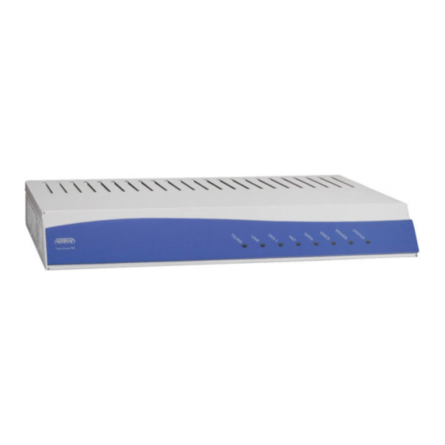
ADTRAN Total Access 900 Series Hardware Installation Manual
Hide thumbs
Also See for Total Access 900 Series:
- Quick configuration manual (2 pages) ,
- Quick start (4 pages) ,
- Quick configuration manual (4 pages)
Table of Contents
Advertisement
Advertisement
Table of Contents


Need help?
Do you have a question about the Total Access 900 Series and is the answer not in the manual?
Questions and answers