Moxa Technologies UC-8540 Series Quick Installation Manual
Hide thumbs
Also See for UC-8540 Series:
- Software user manual (116 pages) ,
- Quick installation manual (14 pages) ,
- User manual (19 pages)
Table of Contents
Advertisement
Quick Links
Quick Installation Guide
Moxa Americas:
Toll-free: 1-888-669-2872
Tel:
1-714-528-6777
Fax:
1-714-528-6778
Moxa Europe:
Tel:
+49-89-3 70 03 99-0
Fax:
+49-89-3 70 03 99-99
Moxa India:
Tel:
+91-80-4172-9088
Fax:
+91-80-4132-1045
UC-8540 Series
Edition 1.0, October 2018
Technical Support Contact Information
www.moxa.com/support
2018 Moxa Inc. All rights reserved.
Moxa China (Shanghai office):
Toll-free: 800-820-5036
Tel:
+86-21-5258-9955
Fax:
+86-21-5258-5505
Moxa Asia-Pacific:
Tel:
+886-2-8919-1230
Fax:
+886-2-8919-1231
P/N: 1802085400010
*1802085400010*
Advertisement
Table of Contents

Subscribe to Our Youtube Channel
Related Manuals for Moxa Technologies UC-8540 Series


Summary of Contents for Moxa Technologies UC-8540 Series
- Page 1 UC-8540 Series Quick Installation Guide Edition 1.0, October 2018 Technical Support Contact Information www.moxa.com/support Moxa Americas: Moxa China (Shanghai office): Toll-free: 1-888-669-2872 Toll-free: 800-820-5036 Tel: 1-714-528-6777 Tel: +86-21-5258-9955 Fax: 1-714-528-6778 Fax: +86-21-5258-5505 Moxa Europe: Moxa Asia-Pacific: Tel: +49-89-3 70 03 99-0...
-
Page 2: Model Names And Package Checklist
– (-40 to 158°F) UC-8540-T-CT-LX -40 to 70°C – (-40 to 158°F) Before you install the UC-8540 Series computer, ensure that the package contains the following items: • UC-8540 Series computer • Mounting kits • CBL-4PINDB9F-100: 4-pin pin header to DB9 female console port cable, 100 cm •... -
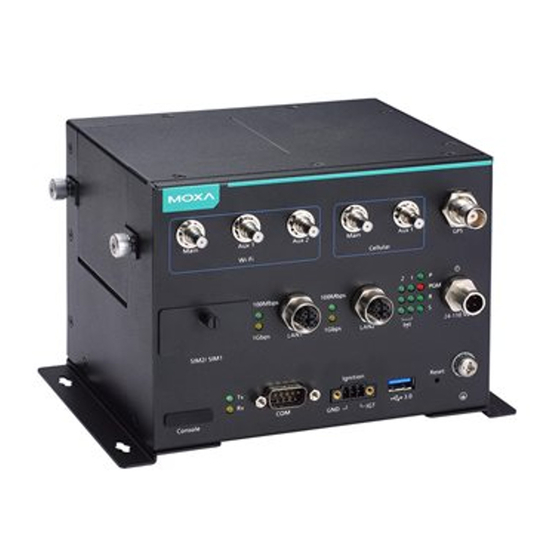
Page 3: Led Indicators
Side View Bottom View LED Indicators Refer to the following table for the LED indicator definitions. LED Name Status Function Green Power is on No power input Green System is ready System is booting up, OS boot-up failure, or other system initialization error Ethernet Green Steady On: 100 Mbps Ethernet link... -
Page 4: Installing The Computer
Installing the Computer Wall or Desk Mounting Use two screws per side to mount the UC-8540 computer on a wall or desk. Wall Mounting Fasten the screws at back side of UC-8540 Desk Mounting Fasten the screws at bottom side of UC-8540 Wiring Requirements Be sure to read and follow these common safety precautions before proceeding with the installation of any electronic device:... -
Page 5: Connecting The Power
ATTENTION Safety First! Be sure to disconnect the power cord before installing and/or wiring your UC-8540 computer. Wiring Caution! Calculate the maximum possible current in each power wire and common wire. Observe all electrical codes dictating the maximum current allowable for each wire size. If the current goes above the maximum ratings, the wiring could overheat, causing serious damage to your equipment. -
Page 6: Connecting To The Network
Connecting to the Network The pin assignments for the UC-8540 computer’s Ethernet port are shown in the following figure. If you are using your own Ethernet cable, make sure that you match the pin assignment on the connector of the Ethernet cable to the pin assignment shown below: LAN Ports x 2, LEDs x 4 (10/100/1000 Mbps, M12) -
Page 7: Connecting A Usb Device
Connecting a USB Device The UC-8540 computer is provided with a USB 3.0 port on the front panel for connecting a USB device. USB Port x 1 (USB 3.0, type A) Connecting the Wi-Fi/Cellular Module and Antenna The UC-8540 computer is provided with two sets of QMA antenna holes for installing antennas for the Wi-Fi and cellular modules. - Page 8 To install a wireless (Wi-Fi/cellular) module, do the following: 1. The thermal pads come attached 2. Insert the wireless module in to the wireless module. Remove the designated socket and the plastic protective film on the tighten the two screws on the thermal pads.
-
Page 9: Installing Sim Cards
Installing SIM Cards Cellular module supports 2 Micro SIM cards. To install Micro SIM cards for the cellular modules, do the following: 1. Open the case of the Micro 2. Push down the Micro SIM-card SIM card socket. into the socket by correct direction.
Need help?
Do you have a question about the UC-8540 Series and is the answer not in the manual?
Questions and answers