Table of Contents
Advertisement
Quick Links
Quick Installation Guide
Moxa Americas:
Toll-free: 1-888-669-2872
Tel:
1-714-528-6777
Fax:
1-714-528-6778
Moxa Europe:
Tel:
+49-89-3 70 03 99-0
Fax:
+49-89-3 70 03 99-99
Moxa India:
Tel:
+91-80-4172-9088
Fax:
+91-80-4132-1045
UC-8410A
Edition 2.0, April 2018
Technical Support Contact Information
www.moxa.com/support
2018 Moxa Inc. All rights reserved.
Moxa China (Shanghai office):
Toll-free: 800-820-5036
Tel:
+86-21-5258-9955
Fax:
+86-21-5258-5505
Moxa Asia-Pacific:
Tel:
+886-2-8919-1230
Fax:
+886-2-8919-1231
P/N: 1802084100011
*1802084100011*
Advertisement
Table of Contents

Related Manuals for Moxa Technologies UC-8410A Series


Summary of Contents for Moxa Technologies UC-8410A Series
- Page 1 UC-8410A Quick Installation Guide Edition 2.0, April 2018 Technical Support Contact Information www.moxa.com/support Moxa Americas: Moxa China (Shanghai office): Toll-free: 1-888-669-2872 Toll-free: 800-820-5036 Tel: 1-714-528-6777 Tel: +86-21-5258-9955 Fax: 1-714-528-6778 Fax: +86-21-5258-5505 Moxa Europe: Moxa Asia-Pacific: Tel: +49-89-3 70 03 99-0 Tel: +886-2-8919-1230 Fax:...
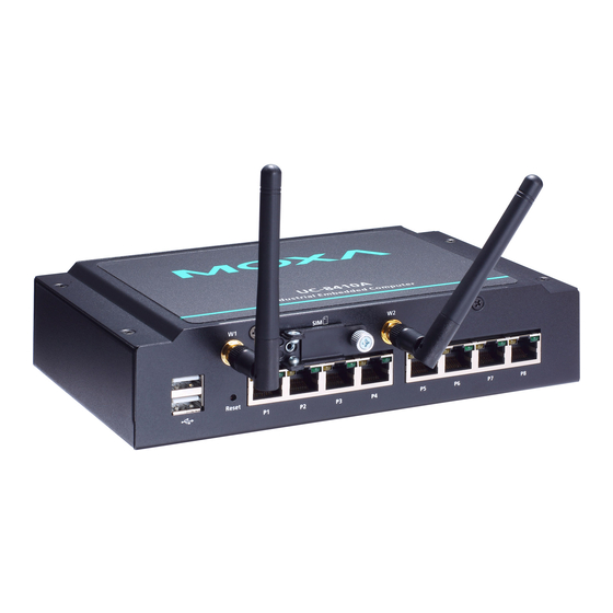
- Page 2 Overview The UC-8410A Series of dual-core embedded computers support a rich variety of communication interfaces, and come with 8 RS-232/422/485 serial ports, 3 Ethernet ports, 1 PCIe mini slot for a wireless module (not for the -NW model), 4 digital input channels, 4 digital output channels, 1 SD card slot, 1 mSATA socket, and 2 USB 2.0 hosts.
- Page 3 Rear View Left-Side View Installing the UC-8410A Wall or Cabinet The two metal brackets included with the UC-8410A can be used to attach it to a wall or the inside of a cabinet. Using two screws per bracket, first attach the brackets to the bottom of the UC-8410A. Next, use two screws per bracket to attach the UC-8410A to a wall or cabinet.
- Page 4 SG: The Shielded Ground (sometimes called Protected Ground) contact is the right most contact on the 3-pin power terminal block connector when viewed from the angle shown here. Connect the SG wire to an appropriate grounded metal surface. An additional ground connector is provided just above the power terminal block, which you can use for grounding protection.
- Page 5 To replace or install the SD card, or to install an mSATA card, follow these steps: 1. Use a screwdriver to remove the screws on the rear and side panels of the cover over the mSATA socket. 2. Remove the cover to access the SD-card slot and the mSATA socket. 3.
- Page 6 Console Port The serial console port is a 4-pin pin-header RS-232 port that is located below the SD card socket. Use a screwdriver to remove the two screws holding the cover to the embedded computer’s housing. The port is used for the serial console terminal, which is useful for viewing boot-up messages.
- Page 7 2. Insert the SIM card into the slot. Make sure you insert the card in the direction indicated above the card slot. 3. Close the cover and fasten the screw. Powering on the UC-8410A Computer To power on the UC-8410A, connect a terminal block to power jack converter to the UC-8410A’s DC terminal block (located on the left rear panel), and then connect the power adapter.
- Page 8 After the boot settings of the LAN interface have been modified, use the following command to activate the LAN settings with immediate effect: #sync; ifup –a NOTE Refer to the UC-8410A Series Linux Software User’s Manual for additional configuration information. - 8 -...
Need help?
Do you have a question about the UC-8410A Series and is the answer not in the manual?
Questions and answers