Table of Contents
Advertisement
Quick Links
We have 45,000 LP502030-PCM-NTC-LD-A02554 - EEMB - Lithium Battery Rectangular 3.7V 250mAh Rechargeable in
stock now. Starting at $0.034. This EEMB part is fully warrantied and traceable.
Looking for a discount?
Check out our current promotions!
This coversheet was created by Verical, a division of Arrow Electronics, Inc. ("Verical"). The attached document was created by the part supplier,
not Verical, and is provided strictly 'as is.' Verical, its subsidiaries, affiliates, employees, and agents make no representations or warranties
regarding the attached document and disclaim any liability for the consequences of relying on the information therein. All referenced brands,
product names, service names, and trademarks are the property of their respective owners.
00000005981LF-000
ADM00795
EOS Power
MICROCHIP TECHNOLOGY
Buy Now
Buy Now
Give us a call
1-855-837-4225
International: 1-555-555-5555
1-415-281-3866
1-415-281-3866
Arrow Electronics,
Arrow Electronics, Inc
Verical Division
9201 East Dry Creek Road
P.O. Box 740970
Centennial, CO 80112
Los Angeles, CA 90074-0970
Advertisement
Table of Contents

Subscribe to Our Youtube Channel
Related Manuals for Microchip Technology HV2903


Summary of Contents for Microchip Technology HV2903
- Page 1 We have 45,000 LP502030-PCM-NTC-LD-A02554 - EEMB - Lithium Battery Rectangular 3.7V 250mAh Rechargeable in stock now. Starting at $0.034. This EEMB part is fully warrantied and traceable. 00000005981LF-000 ADM00795 EOS Power MICROCHIP TECHNOLOGY Buy Now Buy Now Looking for a discount? Check out our current promotions!
- Page 2 HV2903 Analog Switch Evaluation Board User’s Guide 2017 Microchip Technology Inc. DS50002582A...
- Page 3 Select Mode, Total Endurance, TSHARC, UniWinDriver, WiperLock and ZENA are trademarks of Microchip Technology Incorporated in the U.S.A. and other countries. SQTP is a service mark of Microchip Technology Incorporated in the U.S.A. All other trademarks mentioned herein are property of their respective companies.
-
Page 4: Table Of Contents
1.4 HV2903 Analog Switch Evaluation Board - Functional Description ....9 1.5 HV2903 Analog Switch Evaluation Board Technical Kit ....... 11 1.6 What the HV2903 Analog Switch Evaluation Board Kit Includes ....12 Chapter 2. Installation and Operation 2.1 Getting Started ..................... 13 2.2 HV MUX GUI Installation................ - Page 5 A.27 ADM00825 - Bottom Copper and Silk ............44 A.28 ADM00825 - Bottom Silk ................44 Appendix B. Bill of Materials B.1 HV2903 Analog Switch Evaluation Board ............ 45 B.2 HV MUX Controller Board................46 Appendix C. Demo Board Waveforms C.1 Board Typical Waveforms ................
-
Page 6: Preface
Document Revision History DOCUMENT LAYOUT This document describes how to use the HV2903 Analog Switch Evaluation Board as a development tool to evaluate the HV2903 No High-Voltage Bias, Low Harmonic Distortion, 32-Channel, High-Voltage Analog Switch IC. The user’s guide layout is as follows: •... -
Page 7: Conventions Used In This Guide
Curly brackets and pipe Choice of mutually exclusive errorlevel {0|1} character: { | } arguments; an OR selection Ellipses... Replaces repeated text var_name [, var_name...] Represents code supplied by void main (void) user { ... 2017 Microchip Technology Inc. DS50002582A-page 6... -
Page 8: Recommended Reading
HV2903 Analog Switch Evaluation Board User’s Guide RECOMMENDED READING This user’s guide describes how to use the HV2903 Analog Switch Evaluation Board. Another useful document is listed below. The following Microchip document is available and recommended as a supplemental reference resource. -
Page 9: Chapter 1. Product Overview
MD1822 and TC6320 pulser circuit. HV2903 IC - DESCRIPTION The HV2903 is 32-Channel HV Analog Switches without HV Supplies. It is designed for use in applications requiring high-voltage switching controlled by low-voltage control signals, such as medical ultrasound imaging, driving piezoelectric transducers and in printers. - Page 10 HV2903 Analog Switch Evaluation Board User’s Guide The evaluation board features one HV2903/AHA 12x12x1.2 mm 132-lead TFBGA packaged integrated circuit, two MD1822K6-G 3x3x1 mm 16-lead QFN packaged inte- grated circuits and four TC6320K6-G 4x4x1 mm 8-lead DFN packaged NMOS and PMOS pair integrated circuits.
-
Page 11: Hv2903 Analog Switch Evaluation Board Technical Kit
CH1 Pulser MD1822 + TC6320 SW8B SW A 330pF 2.5k SW24B SW24A 330pF 2.5k CH2 Pulser MD1822 + TC6320 SW25B SW25A 330pF 2.5k FIGURE 1-1: HV2903 Analog Switch Evaluation Board Simplified Block Diagram. 2017 Microchip Technology Inc. DS50002582A-page 10... -
Page 12: What The Hv2903 Analog Switch Evaluation Board Kit Includes
HV2903 Analog Switch Evaluation Board User’s Guide WHAT THE HV2903 ANALOG SWITCH EVALUATION BOARD KIT INCLUDES The HV2903 Analog Switch Evaluation Board includes: • HV2903 Analog Switch Evaluation Board (ADM00795) • Important Information Sheet 2017 Microchip Technology Inc. DS50002582A-page 11... -
Page 13: Chapter 2. Installation And Operation
USER’S GUIDE Chapter 2. Installation and Operation GETTING STARTED The HV2903 Analog Switch Evaluation Board is fully assembled and tested. The board requires six power supply voltage rails of +3.3V, +10V, ±6.0V and ±100V. 2.1.1 Additional Tools Required for Operation 1. - Page 14 HV2903 Analog Switch Evaluation Board User’s Guide 4. Read the License Agreement and accept by checking the box corresponding to “I accept the agreement”, then click Next to proceed with the installation. FIGURE 2-2: HV MUX GUI - License Agreement Dialog Box.
- Page 15 8. After the installation has completed, Click Next to continue. FIGURE 2-5: HV MUX GUI - Installation Status Dialog Box. 9. Once Installation Complete dialog box appears, click the Finish button to exit the installer. 2017 Microchip Technology Inc. DS50002582A-page 14...
-
Page 16: Setup Procedure
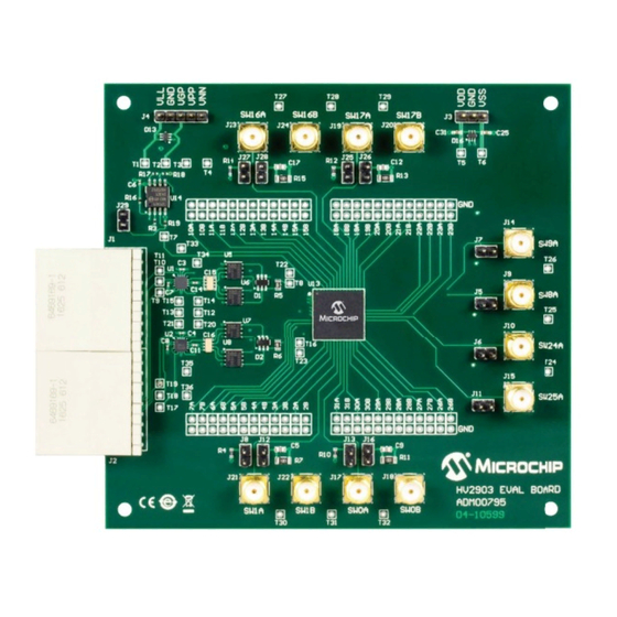
10. Click the Initialize HV MUX Controller button in the GUI and the status window in the bottom will show an “initialization complete” message. 11. Unselect the STBY check box to set HV2903 in normal operation and choose the switching mode by selecting/unselecting the MODE check box. - Page 17 –6V –20 mA J4-1 +3.3V +150 mA J4-2 — J4-3 +5 to +11.5V +10 mA J4-4 +100V +5 mA J11-2 –100V –5 mA FIGURE 2-7: HV2903 Analog Switch Evaluation Board - Front View. 2017 Microchip Technology Inc. DS50002582A-page 16...
-
Page 18: Interface Connections
V on with logic signal low off with logic signal low and V WARNING Powering HV2903 Evaluation Board up/down in an arbitrary sequence may cause damage to the device. INTERFACE CONNECTIONS TABLE 2-3: J2 CONTROL INTERFACE SIGNALS PIN #... -
Page 19: Testing The Hv2903 Analog Switch Evaluation Board
2. Unselect STBY to set HV MUX in normal operation. 3. Unselect MODE to set HV2903 in bank switching mode. 4. Select EN to set HV2903 bank switching to active. If EN is not selected, all the switches are set to OFF. - Page 20 MUX, Start and Stop buttons, the control data set by the user in the GUI changes oper- ation of HV2903 and turn on/off the built-in pulsers in the HV2903 Analog Switch Eval- uation Board. Please see the explanation for each corresponding item.
- Page 21 32 switches of HV2903 are set to ON/OFF states, according to the DIN data entry. 6. EN: when selected, the EN logic input is set to high and HV2903 is set to active for bank switching mode. When unselected, the EN logic input is set to low and ...
-
Page 22: Generation Of Pulser Output At Sw8A Of Hv2903
8. Set HV MUX: when clicked, the data that the user sets at steps 2 to 7 is applied to HV2903. Please note that the 32-bit DIN data, 32 clocks and one negative LE pulse are applied one time only at the individual switching mode. - Page 23 50V/div 50V/div FIGURE 2-10: Typical Waveform of 2:1 MUX Connected to Pulser. 2017 Microchip Technology Inc. DS50002582A-page 22...
- Page 24 HV2903 Analog Switch Evaluation Board User’s Guide NOTES: 2017 Microchip Technology Inc. DS50002582A-page 23...
-
Page 25: Chapter 3. Pcb Design And Layout Notes
High-speed PCB trace design practices are used for the HV2903 PCB layout. The internal circuitry of the HV2903 can operate at quite a high frequency, with the primary speed limitation being the load capacitance. Because of this high speed and the high transient currents that result from driving capacitive loads, the supply voltage bypass capacitors should be as close to the pins as possible. -
Page 26: Appendix A. Schematic & Layouts
USER’S GUIDE Appendix A. Schematic & Layouts INTRODUCTION This appendix contains the following schematics and layouts for the HV2903 Analog Switch Evaluation Board (ADM00795) and the HV MUX Controller Board (ADM00825) • HV2903 Analog Switch Evaluation Board (ADM00795): - ADM00795 - Schematic... -
Page 27: Adm00795 - Schematic
ADM00795 - SCHEMATIC SW8A SW9A 1 uF 250V B1100 0.1uF 0.1uF 0.1uF 0.1uF 0.1uF 0.1uF 0.1uF 0.1uF 0.1uF 0.1uF 0.1uF 0805 0805 0603 0603 0603 0603 0603 0603 0603 0603 0603 2.55k 330 pF 2.55k 330 pF 0603 0603 250V 250V BAT54DW BAT54DW... -
Page 28: Adm00795 - Top Silk
HV2903 Analog Switch Evaluation Board User’s Guide ADM00795 - TOP SILK ADM00795 - TOP COPPER AND SILK 2017 Microchip Technology Inc. DS50002582A-page 27... -
Page 29: Adm00795 - Top Copper
ADM00795 - TOP COPPER ADM00795 - INNER 1 2017 Microchip Technology Inc. DS50002582A-page 28... -
Page 30: Adm00795 - Inner 2
HV2903 Analog Switch Evaluation Board User’s Guide ADM00795 - INNER 2 ADM00795 - INNER 3 2017 Microchip Technology Inc. DS50002582A-page 29... -
Page 31: Adm00795 - Bottom Copper
ADM00795 - BOTTOM COPPER A.10 ADM00795 - BOTTOM COPPER AND SILK 2017 Microchip Technology Inc. DS50002582A-page 30... -
Page 32: Adm00795 - Bottom Silk
HV2903 Analog Switch Evaluation Board User’s Guide A.11 ADM00795 - BOTTOM SILK 2017 Microchip Technology Inc. DS50002582A-page 31... -
Page 33: Adm00825 - Schematic (Connection)
A.12 ADM00825 - SCHEMATIC (CONNECTION) FPGA01.SchDoc Connector.SchDoc MUPB001_PWR.SchDoc IO_2V5_0_P USB_TO_SPI.SchDoc IO_2V5_0_P IO_2V5_0_P IO_2V5_0_N SPI_CSBAR IO_2V5_0_N IO_2V5_0_N IO_2V5_1_P CSBAR CSBAR SPI_SCK IO_2V5_1_P IO_2V5_1_P IO_2V5_1_N SPI_MOSI IO_2V5_1_N IO_2V5_1_N MOSI MOSI SPI_MISO IO_2V5_2_P MISO MISO IO_2V5_2_P IO_2V5_2_P IO_2V5_2_N FPGA_RST IO_2V5_2_N IO_2V5_2_N IO_2V5_3_P FPGA_RST FPGA_RST SPI_RST IO_2V5_3_P... -
Page 34: Adm00825 - Schematic (Power Supply)
A.13 ADM00825 - SCHEMATIC (POWER SUPPLY) 22000pF 0603 ON-POWER ON XAL6060 Via_2.5x1.5 20BQ030P 0.1uF 10uF 10uF 10uF 10uF POWER 2.5mm 10uF 10uF 10uF 0603 0.1uF 0603 0603 0805 0805 0805 0805 1206 1206 1206 0603 GREEN GND_D 8.66k GND_D 0603 GND_D 390R GND_D... -
Page 35: Adm00825 - Schematic (Usb To Spi)
A.14 ADM00825 - SCHEMATIC (USB TO SPI) 3V3_VDD C103 C106 4.7uF 0.1uF USB_CONFIG LED, ON- SUSPEND, OFF - ACTIVE 1206 0603 GND_D 0603 GND_D MCP2210 SSOP-20 12MHz USB_D+ OSC1 OSC1 OSC1 USB MINI-B Female 3V3_VDD USB_D- OSC2 OSC2 OSC2 VBUS VUSB VUSB USB_D-... -
Page 36: Adm00825 - Schematic (Programmable Clock)
A.15 ADM00825 - SCHEMATIC (PROGRAMMABLE CLOCK) GND_D 0603 XTAL-40MHz 0.1uF 40MHz_N 100R GND_D 0603 40MHz_P 0.1uF 0603 CLK5 3V3_CLK VOUT VOUT 100k GND_D GND_D C107 0603 4.7uF 10000pF 4.7uF 0.010uF 4700pF 10000pF 10000pF 10000pF 10000pF 10000pF 10000pF 0603 MIC94325YMT-TR GND_D 0603 0603 0603... -
Page 37: Adm00825 - Schematic (Fpga)
A.16 ADM00825 - SCHEMATIC (FPGA) 3V3_VDD 4.7k 0603 OUT1 IO_L65N_CSO_B_2 EXT_INT IO_L66N_SCP0_0 CTRL_OEB IO_L83N_VREF_3 IO_2V5_0_N IO_L74N_DOUT_BUSY_1 INIT_B OUT2 IO_L65P_INIT_B_2 IO_L66P_SCP1_0 CTRL_OED IO_L83P_3 IO_2V5_0_P IO_L74P_AWAKE_1 IO_L64N_D9_2 IO_L65N_SCP2_0 CTRL_OEC IO_L52N_3 IO_2V5_1_N IO_L47N_1 IO_2V5_13_N IO_L64P_D8_2 MOSI IO_L65P_SCP3_0 CTRL_SDI IO_L52P_3 IO_2V5_1_P IO_L47P_1 IO_2V5_13_P IO_L62N_D6_2 MISO IO_L64N_SCP4_0 CTRL_CSB... -
Page 38: Adm00825 - Schematic (Fpga Decoupling Capacitors)
A.17 ADM00825 - SCHEMATIC (FPGA DECOUPLING CAPACITORS) For 1V2_VCCINT 1V2_VCCINT 100uF 47nF 1000pF 1000pF 1000pF 1000pF 1000pF 6.3V TANT-B 0603 0603 0603 0603 0603 0603 GND_D For VCCO_1 For VCCAUX For VCCO_0 2V5_VDD 3V3_VDD 3V3_VDD 33uF 33uF 33uF 47nF 1000pF 1000pF 1000pF 47nF... -
Page 39: Adm00825 - Schematic (Connectors)
A.18 ADM00825 - SCHEMATIC (CONNECTORS) PWR5V0 PWR5V0 33uF 33uF 0.1uF 0.1uF TANT-B TANT-B 0603 0603 GND_D GND_D IO_2V5_0_P IO_2V5_15_P IO_2V5_0_N IO_2V5_15_N IO_2V5_1_P IO_2V5_2_P IO_2V5_16_P IO_2V5_17_P IO_2V5_1_N IO_2V5_2_N IO_2V5_16_N IO_2V5_17_N IO_2V5_3_P IO_2V5_4_P IO_2V5_18_P IO_2V5_19_P IO_2V5_3_N IO_2V5_4_N IO_2V5_18_N IO_2V5_19_N IO_2V5_5_P IO_2V5_6_P IO_2V5_20_P IO_2V5_21_P IO_2V5_5_N IO_2V5_6_N... -
Page 40: Adm00825 - Top Silk
HV2903 Analog Switch Evaluation Board User’s Guide A.19 ADM00825 - TOP SILK A.20 ADM00825 - TOP COPPER AND SILK 2017 Microchip Technology Inc. DS50002582A-page 39... -
Page 41: Adm00825 - Top Copper
A.21 ADM00825 - TOP COPPER A.22 ADM00825 - INNER 1 2017 Microchip Technology Inc. DS50002582A-page 40... -
Page 42: Adm00825 - Inner 2
HV2903 Analog Switch Evaluation Board User’s Guide A.23 ADM00825 - INNER 2 A.24 ADM00825 - INNER 3 2017 Microchip Technology Inc. DS50002582A-page 41... -
Page 43: Adm00825 - Inner 4
A.25 ADM00825 - INNER 4 A.26 ADM00825 - BOTTOM COPPER 2017 Microchip Technology Inc. DS50002582A-page 42... -
Page 44: Adm00825 - Bottom Copper And Silk
HV2903 Analog Switch Evaluation Board User’s Guide A.27 ADM00825 - BOTTOM COPPER AND SILK A.28 ADM00825 - BOTTOM SILK 2017 Microchip Technology Inc. DS50002582A-page 43... -
Page 45: Appendix B. Bill Of Materials
HV2903 ANALOG SWITCH EVALUATION BOARD USER’S GUIDE Appendix B. Bill of Materials HV2903 ANALOG SWITCH EVALUATION BOARD TABLE B-1: BILL OF MATERIALS (BOM) Qty. Reference Description Manufacturer Part Number C1, C2, C19, C20, Capacitor TDK Corporation C4532X7T2E105M250KA C21, C22 C10, C13, C27, C28... -
Page 46: Hv Mux Controller Board
HV2903 Analog Switch Evaluation Board User’s Guide TABLE B-1: BILL OF MATERIALS (BOM) (CONTINUED) Qty. Reference Description Manufacturer Part Number T24, T25, T26, T27, Test Point — — T28, T29, T30, T31, T32, T33, T34, T35, U1, U2 MD1822 Microchip Technology Inc. - Page 47 RES TKF 8.66k 1% 1/10W Yageo Corporation RC0603FR-078K66L SMD 0603 Note 1: The components listed in this Bill of Materials are representative of the PCB assembly. The released BOM used in manufacturing uses all RoHS-compliant components. 2017 Microchip Technology Inc. DS50002582A-page 46...
- Page 48 HV2903 Analog Switch Evaluation Board User’s Guide TABLE B-2: BILL OF MATERIALS (BOM) (CONTINUED) Qty. Reference Description Manufacturer Part Number R22, R28, R29, R33, RES TF 10k 1% 1/8W SMD Vishay Beyschlag MCT06030C1002FP50 R38, R42 0603 ® R23, R24, R30, R50...
- Page 49 40 Ohm -20°C ~ 70°C Surface Mount 4-SMD Note 1: The components listed in this Bill of Materials are representative of the PCB assembly. The released BOM used in manufacturing uses all RoHS-compliant components. 2017 Microchip Technology Inc. DS50002582A-page 48...
- Page 50 HV2903 Analog Switch Evaluation Board User’s Guide NOTES: 2017 Microchip Technology Inc. DS50002582A-page 49...
-
Page 51: Appendix C. Demo Board Waveforms
SW8A (SW8 ON) 5V/div SW9A (SW9 OFF) 100V/div SW24A (SW24 ON) 5V/div SW25A (SW25 OFF) FIGURE C-2: 5 MHz 10 Pulses, VPP/VNN = ±100V, VDD/VSS = ±6V, VGP = 10V, 330 pF//2.5 KΩ Load. 2017 Microchip Technology Inc. DS50002582A-page 50... - Page 52 HV2903 Analog Switch Evaluation Board User’s Guide 2017 Microchip Technology Inc. DS50002582A-page 51...
-
Page 53: Worldwide Sales And Service
New York, NY Tel: 46-31-704-60-40 Tel: 631-435-6000 Sweden - Stockholm San Jose, CA Tel: 46-8-5090-4654 Tel: 408-735-9110 UK - Wokingham Tel: 408-436-4270 Tel: 44-118-921-5800 Canada - Toronto Fax: 44-118-921-5820 Tel: 905-695-1980 Fax: 905-695-2078 2017 Microchip Technology Inc. DS50002582A-page 52 10/25/17...
Need help?
Do you have a question about the HV2903 and is the answer not in the manual?
Questions and answers