
Related Manuals for Microchip Technology HV2722


Summary of Contents for Microchip Technology HV2722
- Page 1 HV2722 Analog Switch Evaluation Board User’s Guide 2019 Microchip Technology Inc. DS50002810A...
- Page 2 Technology, and Symmcom are registered trademarks of Microchip Technology Inc. in other countries. GestIC is a registered trademark of Microchip Technology Germany II GmbH & Co. KG, a subsidiary of Microchip Technology Inc., in other countries. All other trademarks mentioned herein are property of their respective companies.
-
Page 3: Table Of Contents
1.2 HV2722 Device Short Overview ..............9 1.3 HV2722 Analog Switch Evaluation Board Features ........9 1.4 What is the HV2722 Analog Switch Evaluation Board? ....... 10 1.5 HV2722 Analog Switch Evaluation Board Technical Parameters ....10 1.6 HV2722 Analog Switch Evaluation Board Kit Contents ........ 11 Chapter 2. - Page 4 HV2722 Analog Switch Evaluation Board User’s Guide NOTES: 2019 Microchip Technology Inc. DS50002810A-page 4...
-
Page 5: Preface
Customer Support • Document Revision History DOCUMENT LAYOUT This document describes how to use the HV2722 Analog Switch Evaluation Board as a development tool to emulate and debug firmware on a target board. The manual layout is as follows: •... -
Page 6: Conventions Used In This Guide
HV2722 Analog Switch Evaluation Board User’s Guide CONVENTIONS USED IN THIS GUIDE This manual uses the following documentation conventions: DOCUMENTATION CONVENTIONS Description Represents Examples Arial font: ® Italic characters Referenced books MPLAB IDE User’s Guide Emphasized text ...is the only compiler... -
Page 7: Recommended Reading
Preface RECOMMENDED READING This user’s guide describes how to use the HV2722 Analog Switch Evaluation Board. Another useful document is listed below. The following Microchip document is available and recommended as a supplemental reference resource: HV2621/HV2721/HV2722 Data Sheet – “300V, Low-Charge Injection, 16-Channel, High-Voltage Analog Switch”... - Page 8 HV2722 Analog Switch Evaluation Board User’s Guide NOTES: 2019 Microchip Technology Inc. DS50002810A-page 8...
-
Page 9: Chapter 1. Product Overview
USER’S GUIDE Chapter 1. Product Overview INTRODUCTION The HV2722 Analog Switch Evaluation Board (ADM00946) works with the HV MUX Controller Board (ADM00825) to provide No High-Voltage Bias, 32-Channel, High-Voltage Analog Switches with L-Switch Architecture demonstration, including basic on/off switch operation, and 2:1 MUX operation with two built-in MD1822, TP2640 and TN2640 pulser circuits. -
Page 10: What Is The Hv2722 Analog Switch Evaluation Board
HV2722 Analog Switch Evaluation Board User’s Guide WHAT IS THE HV2722 ANALOG SWITCH EVALUATION BOARD? The HV2722 Analog Switch Evaluation Board can control the HV2722 device’s operation and built-in pulsers that are connected to the two 2:1 MUX switches for demonstration. -
Page 11: Hv2722 Analog Switch Evaluation Board Kit Contents
Product Overview FIGURE 1-1: HV2722 ANALOG SWITCH EVALUATION BOARD SIMPLIFIED BLOCK DIAGRAM HV2722 ANALOG SWITCH EVALUATION BOARD KIT CONTENTS The HV2722 Analog Switch Evaluation Board includes: • HV2722 Analog Switch Evaluation Board (ADM00946) • Important Information Sheet 2019 Microchip Technology Inc. - Page 12 HV2722 Analog Switch Evaluation Board User’s Guide NOTES: 2019 Microchip Technology Inc. DS50002810A-page 12...
-
Page 13: Chapter 2. Installation And Operation
Chapter 2. Installation and Operation GETTING STARTED The HV2722 Analog Switch Evaluation Board is fully assembled and tested. The board requires six power supply voltage rails of +5V, +10V, ±135V and ±150V. The +5V is supplied from the HV MUX Controller Board and the others need to be supplied from external power supplies. - Page 14 HV2722 Analog Switch Evaluation Board User’s Guide FIGURE 2-1: HV MUX GUI – APPLICATION INSTALL DIALOG BOX 4. Read the License Agreement and accept it by checking the box corresponding to “I accept the agreement”. Click Next to proceed with the installation.
- Page 15 6. Once the installation path is chosen, the software is ready to install. Click Next. FIGURE 2-4: HV MUX GUI – READY TO INSTALL DIALOG BOX 7. The Installation Status window appears, showing the installation progress. 8. After the installation has completed, click Next. 2019 Microchip Technology Inc. DS50002810A-page 15...
- Page 16 HV2722 Analog Switch Evaluation Board User’s Guide FIGURE 2-5: HV MUX GUI – INSTALLATION STATUS DIALOG BOX 9. Once the Installation Complete dialog box appears, click the Finish button to exit the installer. FIGURE 2-6: HV MUX GUI – INSTALLATION COMPLETE DIALOG BOX ...
-
Page 17: Hv2722 Analog Switch Evaluation Board Setup Procedure
10. Clear the STBY check box and select the MODE check box. (Do not change these states. Not used for HV2722EVB.) 11. Click the Set HV MUX button. All digital control signals are applied to HV2722. 12. Set the number of pulses and T time of the pulser. - Page 18 Power-Down Description and V +P and -P off +P and -P on and V WARNING Powering the HV2722 Analog Switch Evaluation Board up/down in an arbitrary sequence may cause damage to the device. 2019 Microchip Technology Inc. DS50002810A-page 18...
-
Page 19: Interface Connections
LVCMOS-2.5V Output EEPROM Serial Data Output J2-B3 MOSI — LVCMOS-2.5V Input EEPROM Serial Data Input J2-A5 LVCMOS-3.3V Input HV2722 Latch Clear Logic Input J2-B5 LVCMOS-3.3V Input HV2722 Clock Logic Input J2-C5 LVCMOS-3.3V Input HV2722 Latch Enable Logic Input J2-A6 LVCMOS-3.3V Input... -
Page 20: Hv Mux Controller Board Setup Procedure
The HV MUX Controller Board generates control signals for the HV2722 Analog Switch Evaluation Board and features a Spartan-6 XC6SLX9 FPGA. 1. Before powering up the HV2722 Analog Switch Evaluation Board and the HV MUX Controller Board, make sure that the latest GUI software is installed on the PC. -
Page 21: Testing The Hv2722 Analog Switch Evaluation Board
4. Put 16-bit data (from bit 15 to bit 0) in DIN to set switches on and off. Bit 31 to Bit 16 data are not used for the HV2722 Evaluation Board. Data ‘1’ means the switch is on and data ‘0’ means the switch is off. - Page 22 HV2722 Analog Switch Evaluation Board User’s Guide FIGURE 2-9: TYPICAL WAVEFORM OF 2:1 MUX CONNECTED TO PULSER 50V/div 50V/div 2019 Microchip Technology Inc. DS50002810A-page 22...
-
Page 23: Chapter 3. Gui Description
By clicking the Set HV MUX, Start and Stop buttons, the control data set by the user in the GUI changes the operation of HV2722 and turns on/off the built-in pulsers in the HV2722 Analog Switch Evaluation Board. Follow the explanation for each corresponding item. - Page 24 When this check box is selected, the CLR logic input is set to high and all the switches of HV2722 are set to off. When cleared, the CLR logic input is set to low and the 16 switches of HV2722 are set to On/Off states according to the DIN data entry.
-
Page 25: Chapter 4. Pcb Design And Layout Notes
4.1.1 High-Voltage and High-Speed Grounding and Layout Techniques The center pad at the bottom of the HV2722 QFN package is internally connected to , and should be connected to V externally on the PCB. The user must pay attention to the connecting traces, since the analog switches pass the high-voltage and high-speed signals. - Page 26 HV2722 Analog Switch Evaluation Board User’s Guide NOTES: 2019 Microchip Technology Inc. DS50002810A-page 26...
-
Page 27: Appendix A. Schematics And Layouts
USER’S GUIDE Appendix A. Schematics and Layouts INTRODUCTION This appendix contains the following schematics and layouts for the HV2722 Analog Switch Evaluation Board (ADM00946) and the HV MUX Controller Board (ADM00825). • HV2722 Analog Switch Evaluation Board (ADM00946): Figure A-1: ADM00946 – Schematic Figure A-2: ADM00946 –... - Page 28 DOUT 1206 1206 1 μF 0.1 μF 0.1 μF 450V 500V 500V 2220 1210 1210 Flash 0.1 μF RGND SPI_FLASH.SchDoc HV2722 QFN-64 0603 HV2722 MOSI MOSI 0603 MISO MISO 1 μF 0.1 μF 0.1 μF 450V 500V 500V 2220 1210 1210 HDR-2.54 Male 2x8...
- Page 29 FIGURE A-2: ADM00946 – SCHEMATIC (OUTPUT CONNECTORS) MCP1702/3.3V VDD_MUPB 1 μF 1 μF 0603 0603 0.1 μF 0603 MISO MISO MOSI MOSI DMP1 DMP2 BG10 DG10 BG10 DG10 CON HDR HM ZD 40POS T4 T3 CONN HEADER 40POS CON HDR HM ZD 40POS CONN HEADER 40POS...
- Page 30 FIGURE A-3: ADM00946 – SCHEMATIC (POWER) HDR-2.54 Male 1x2 4.7 μF RS1G RS1G 1 μF 1 μF RS1G 450V 450V 0805 2220 2220 1 2 3 4 5 RS1G 1 μF 1 μF RS1G 450V 450V HDR-2.54 Male 1x5 2220 2220...
- Page 31 FIGURE A-4: ADM00946 – SCHEMATIC (PULSE GENERATOR 1) R1_P1 D8_P1 C9_P1 C10_P1 1 μF 0.1 μF 0805 450V 500V 2220 1210 T14_P1 C11_P1 TP2640LG-G 10000 pF 6 7 8 6 7 8 T15_P1 T36_P1 C19_P1 TN2640LG-G 10000 pF T33_P1 D9_P1 T34_P1 R2_P1 D10_P1...
- Page 32 FIGURE A-5: ADM00946 – SCHEMATIC (PULSE GENERATOR 2) R1_P2 D8_P2 C9_P2 C10_P2 1 μF 0.1 μF 0805 450V 500V 2220 1210 T14_P2 TP2640LG-G C11_P2 10000 pF 6 7 8 6 7 8 T36_P2 T15_P2 C19_P2 TN2640LG-G 10000 pF T33_P2 D9_P2 T34_P2 R2_P2 D10_P2...
- Page 33 FIGURE A-6: ADM00946 – SCHEMATIC (SPI FLASH) VDD_MUPB VDD_MUPB VDD_MUPB 4.7k 0.1 μF 0402 100R 0402 0402 MISO MISO SO/IO1 HOLD/IO3/RESET WP/IO2 MOSI 0402 SI/IO0 MOSI S25FL127SABMFV101 VDD_MUPB 100R 0402 4.7k 0402...
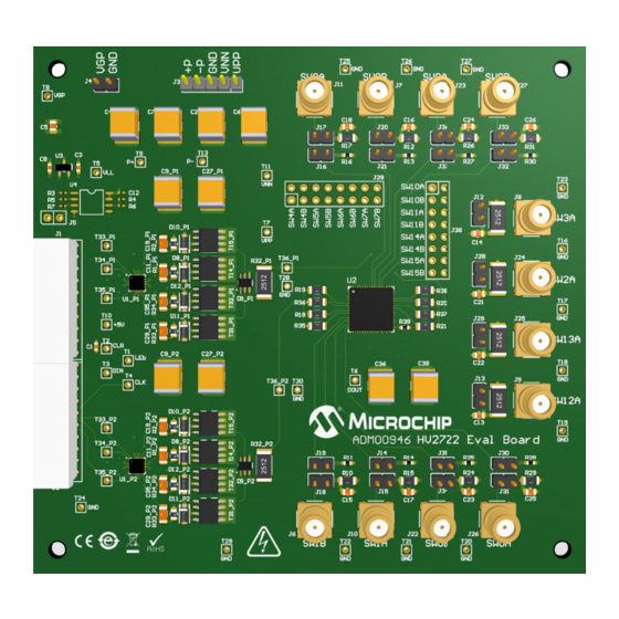
- Page 34 HV2722 Analog Switch Evaluation Board User’s Guide FIGURE A-7: ADM00946 – TOP SILK FIGURE A-8: ADM00946 – TOP COPPER AND SILK 2019 Microchip Technology Inc. DS50002810A-page 34...
- Page 35 Schematics and Layouts FIGURE A-9: ADM00946 – TOP COPPER FIGURE A-10: ADM00946 – INNER 1 2019 Microchip Technology Inc. DS50002810A-page 35...
- Page 36 HV2722 Analog Switch Evaluation Board User’s Guide FIGURE A-11: ADM00946 – INNER 2 FIGURE A-12: ADM00946 – INNER 3 2019 Microchip Technology Inc. DS50002810A-page 36...
- Page 37 Schematics and Layouts FIGURE A-13: ADM00946 – BOTTOM COPPER FIGURE A-14: ADM00946 – BOTTOM COPPER AND SILK 2019 Microchip Technology Inc. DS50002810A-page 37...
- Page 38 HV2722 Analog Switch Evaluation Board User’s Guide FIGURE A-15: ADM00946 – BOTTOM SILK 2019 Microchip Technology Inc. DS50002810A-page 38...
- Page 39 FIGURE A-16: ADM00825 – SCHEMATIC (CONNECTION) FPGA01.SchDoc Connector.SchDoc MUPB001_PWR.SchDoc USB_TO_SPI.SchDoc IO_2V5_0_P IO_2V5_0_P IO_2V5_0_P IO_2V5_0_N SPI_CSBAR IO_2V5_0_N IO_2V5_0_N CSBAR CSBAR IO_2V5_1_P SPI_SCK IO_2V5_1_P IO_2V5_1_P IO_2V5_1_N IO_2V5_1_N IO_2V5_1_N SPI_MOSI MOSI MOSI SPI_MISO MISO MISO IO_2V5_2_P IO_2V5_2_P IO_2V5_2_P IO_2V5_2_N FPGA_RST IO_2V5_2_N IO_2V5_2_N FPGA_RST FPGA_RST IO_2V5_3_P IO_2V5_3_P...
- Page 40 FIGURE A-17: ADM00825 – SCHEMATIC (POWER SUPPLY) 22000pF 0603 ON-POWER ON XAL6060 Via_2.5x1.5 20BQ030P 0.1uF 10uF 10uF 10uF 10uF POWER 2.5mm 10uF 10uF 10uF 0603 0.1uF 0603 0603 0805 0805 0805 0805 1206 1206 1206 0603 GREEN GND_D 8.66k GND_D 0603 GND_D 390R...
- Page 41 FIGURE A-18: ADM00825 – SCHEMATIC (USB TO SPI) 3V3_VDD C103 C106 4.7uF 0.1uF USB_CONFIG LED, ON- SUSPEND, OFF - ACTIVE 1206 0603 GND_D 0603 GND_D MCP2210 SSOP-20 12MHz USB_D+ OSC1 OSC1 OSC1 USB MINI-B Female 3V3_VDD USB_D- OSC2 OSC2 OSC2 VBUS VUSB VUSB...
- Page 42 FIGURE A-19: ADM00825 – SCHEMATIC (PROGRAMMABLE CLOCK) GND_D 0603 XTAL-40MHz 0.1uF 40MHz_N 100R GND_D 0603 40MHz_P 0.1uF 0603 CLK5 3V3_CLK VOUT VOUT 100k GND_D GND_D C107 0603 4.7uF 10000pF 4.7uF 0.010uF 4700pF 10000pF 10000pF 10000pF 10000pF 10000pF 10000pF 0603 MIC94325YMT-TR GND_D 0603 0603...
- Page 43 FIGURE A-20: ADM00825 – SCHEMATIC (FPGA) 3V3_VDD 4.7k OUT1 0603 IO_L65N_CSO_B_2 EXT_INT IO_L66N_SCP0_0 CTRL_OEB IO_L83N_VREF_3 IO_2V5_0_N IO_L74N_DOUT_BUSY_1 INIT_B OUT2 IO_L65P_INIT_B_2 IO_L66P_SCP1_0 CTRL_OED IO_L83P_3 IO_2V5_0_P IO_L74P_AWAKE_1 IO_L64N_D9_2 IO_L65N_SCP2_0 CTRL_OEC IO_L52N_3 IO_2V5_1_N IO_L47N_1 IO_2V5_13_N IO_L64P_D8_2 MOSI IO_L65P_SCP3_0 CTRL_SDI IO_L52P_3 IO_2V5_1_P IO_L47P_1 IO_2V5_13_P IO_L62N_D6_2 MISO IO_L64N_SCP4_0...
- Page 44 FIGURE A-21: ADM00825 – SCHEMATIC (FPGA DECOUPLING CAPACITORS) For 1V2_VCCINT 1V2_VCCINT 100uF 47nF 1000pF 1000pF 1000pF 1000pF 1000pF 6.3V TANT-B 0603 0603 0603 0603 0603 0603 GND_D For VCCO_1 For VCCAUX For VCCO_0 2V5_VDD 3V3_VDD 3V3_VDD 33uF 33uF 33uF 47nF 1000pF 1000pF 1000pF...
- Page 45 FIGURE A-22: ADM00825 – SCHEMATIC (CONNECTORS) PWR5V0 PWR5V0 33uF 33uF 0.1uF 0.1uF TANT-B TANT-B 0603 0603 GND_D GND_D IO_2V5_0_P IO_2V5_15_P IO_2V5_0_N IO_2V5_15_N IO_2V5_1_P IO_2V5_2_P IO_2V5_16_P IO_2V5_17_P IO_2V5_1_N IO_2V5_2_N IO_2V5_16_N IO_2V5_17_N IO_2V5_3_P IO_2V5_4_P IO_2V5_18_P IO_2V5_19_P IO_2V5_3_N IO_2V5_4_N IO_2V5_18_N IO_2V5_19_N IO_2V5_5_P IO_2V5_6_P IO_2V5_20_P IO_2V5_21_P IO_2V5_5_N...
- Page 46 HV2722 Analog Switch Evaluation Board User’s Guide FIGURE A-23: ADM00825 – TOP SILK FIGURE A-24: ADM00825 – TOP COPPER AND SILK 2019 Microchip Technology Inc. DS50002810A-page 46...
- Page 47 Schematics and Layouts FIGURE A-25: ADM00825 – TOP COPPER FIGURE A-26: ADM00825 – INNER 1 2019 Microchip Technology Inc. DS50002810A-page 47...
- Page 48 HV2722 Analog Switch Evaluation Board User’s Guide FIGURE A-27: ADM00825 – INNER 2 FIGURE A-28: ADM00825 – INNER 3 2019 Microchip Technology Inc. DS50002810A-page 48...
- Page 49 Schematics and Layouts FIGURE A-29: ADM00825 – INNER 4 FIGURE A-30: ADM00825 – BOTTOM COPPER 2019 Microchip Technology Inc. DS50002810A-page 49...
- Page 50 HV2722 Analog Switch Evaluation Board User’s Guide FIGURE A-31: ADM00825 – BOTTOM COPPER AND SILK FIGURE A-32: ADM00825 – BOTTOM SILK 2019 Microchip Technology Inc. DS50002810A-page 50...
-
Page 51: Appendix B. Bill Of Materials (Bom)
HV2722 ANALOG SWITCH EVALUATION BOARD USER’S GUIDE Appendix B. Bill of Materials (BOM) HV2722 ANALOG SWITCH EVALUATION BOARD (ADM00946) TABLE B-1: ADM00946 – BILL OF MATERIALS (BOM) Qty. Reference Description Manufacturer Part Number C1, C20, C30_P1, Capacitor, Ceramic, 0.1 μF, Cal-Chip Electronics Inc. - Page 52 HV2722 Analog Switch Evaluation Board User’s Guide TABLE B-1: ADM00946 – BILL OF MATERIALS (BOM) (CONTINUED) Qty. Reference Description Manufacturer Part Number J1, J2 Connector, Header, 40 POS, TE Connectivity AMP 6469169-1 R/A, HM-ZD, Tin Connectors Connector, HDR-2.54, Male, Samtec, Inc.
-
Page 53: Hv Mux Controller Board (Adm00825)
Part Number U1_P1, U1_P2 Microchip Analog, FET Driver Microchip Technology MD1822K6-G Quad-Two Inverting – Two Inc. Noninverting, MD1822K6-G, 16-Lead QFN IC Logic, HV2722 x16, Microchip Technology HV2722 Analog Switch, 300V, QFN-64 Inc. Microchip Analog, LDO, 3.3V, Microchip Technology MCP1702-3302E/CB MCP1702-3302E/CB Inc. - Page 54 HV2722 Analog Switch Evaluation Board User’s Guide TABLE B-2: ADM00825 – BILL OF MATERIALS (BOM) (CONTINUED) Qty. Reference Description Manufacturer Part Number C5, C6, C7, C8, Capacitor, Ceramic, 1000 pF, NMC0603X7R102K50TRPF C9, C14, C15, 50V, 10%, X7R, SMD, 0603 Components Corp.
- Page 55 Vishay CRCW0603100RJNEA 1/10W, SMD, 0603 Intertechnology, Inc. Note 1: The components listed in this Bill of Materials are representative of the PCB assembly. The released BOM used in manufacturing uses all RoHS-compliant components. 2019 Microchip Technology Inc. DS50002810A-page 55...
- Page 56 HV2722 Analog Switch Evaluation Board User’s Guide TABLE B-2: ADM00825 – BILL OF MATERIALS (BOM) (CONTINUED) Qty. Reference Description Manufacturer Part Number Resistor, TKF, 22R, 5%, Panasonic - ECG ERJ-3GSYJ220V 1/10W, SMD, 0603 ® Switch, Slide, SPDT, Mini, Jameco Electronics G4050X-R 50V, 0.5A, G4050X-R, TH...
-
Page 57: Appendix C. Demo Board Waveforms
5 MHz, 5 PULSES, +P/-P = ±100V, V = ±115V, V = 10V, 330 pF//2.5 k Load 100V/div SW2A (SW2 On) 5V/div SW3A (SW3 Off) 100V/div SW12A (SW12 On) 5V/div SW13A (SW13 Off) 2019 Microchip Technology Inc. DS50002810A-page 57... -
Page 58: Worldwide Sales And Service
New York, NY Tel: 46-31-704-60-40 Tel: 631-435-6000 Sweden - Stockholm San Jose, CA Tel: 46-8-5090-4654 Tel: 408-735-9110 UK - Wokingham Tel: 408-436-4270 Tel: 44-118-921-5800 Canada - Toronto Fax: 44-118-921-5820 Tel: 905-695-1980 Fax: 905-695-2078 2019 Microchip Technology Inc. DS50002810A-page 28 05/14/19...
Need help?
Do you have a question about the HV2722 and is the answer not in the manual?
Questions and answers