Advertisement
DART-MX8M-PLUS based on NXP i.MX 8M Plus
Evaluation Kit Quick Start Guide
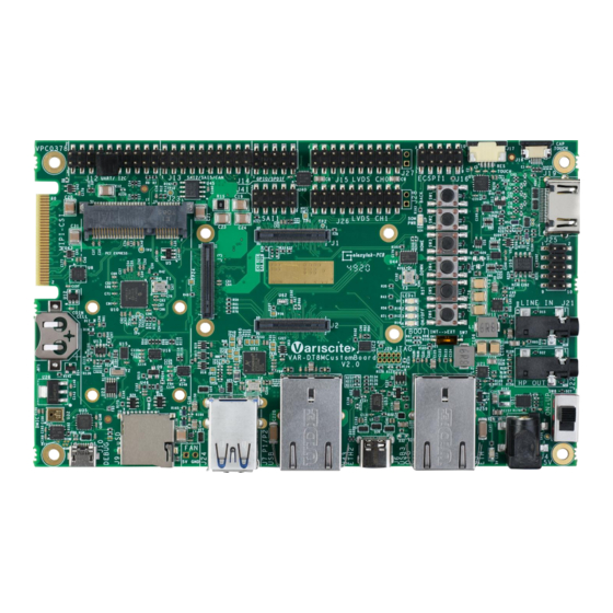
Features
1.
5V PWR IN (J4)
2.
Gigabit Ethernet (J5)
3.
USB 3.0 OTG (J6)
4.
USB 3.0 Host P2(J7)
5.
USB 3.0 Host P1(J8)
6.
SD-MMC (J9)
7.
USB Debug (J10)
8.
RTC BAT. Slot (JBT1)
9.
Single MIPI-CSI (J11)
10.
Mini PCIe #1 (J23)
11.
UART, I2C (J12)
12.
SAI2, SAI5, PDM, CAN (J13)
13.
FAN 5V (J24)
14.
GPIO, SPDIF (J14)
15.
SAI1 (J25)
16.
LVDS CH0 (J15)
17.
LVDS CH1 (J26)
18.
ECSPI, Host wake (J16)
19.
Resistive Touch (J17)
20.
Capacitive Touch (J18)
21.
HDMI(J19)
22.
User Buttons (SW1-TOP:
SW4-BOT)
23.
Reset Button (SW5)
24.
ON/OFF Button (SW6)
25.
Line In (J21)
26.
Boot Select Switch (SW7)
27.
Headphones (J22)
28.
Power ON (SW8)
Evaluation kit initial Setup
1. Carefully remove the 7" LCD and
VAR-DT8MCustomBoard from the package.
2. Connect the 7" LCD Display and Touch cables to the
Evaluation Kit connectors J15, J18 respectively.
Note:connect the display cable with the red wire on pin
1. Connect the touch cable with the metal contacts
facing down.
3. Plug the USB type A to micro B cable between the USB
debug connector (J10) and a PC USB port.
4. Peel off the plastic layer on the bottom of the heat sink
and place the exposed sticky surface on top of the
SOC.
5. Connect the supplied antenna to the antenna U.FL
connector on the SOM for Wi-Fi and Bluetooth radio.
6. Set Power ON switch (SW7) to ON state.
Boot messages are printed within PC's terminal
7.
window.
Advertisement
Table of Contents

Related Manuals for Variscite DART-MX8M-PLUS


Summary of Contents for Variscite DART-MX8M-PLUS
- Page 1 DART-MX8M-PLUS based on NXP i.MX 8M Plus Evaluation Kit Quick Start Guide Features Evaluation kit initial Setup 1. Carefully remove the 7” LCD and 5V PWR IN (J4) Gigabit Ethernet (J5) VAR-DT8MCustomBoard from the package. USB 3.0 OTG (J6) 2. Connect the 7” LCD Display and Touch cables to the USB 3.0 Host P2(J7)
- Page 2 The microSD card is supplied within the package. Updated SD card images can also be downloaded from the Variscite FTP server. See more details in the recovery SD card section in the Variscite wiki pages. 1. Set Power ON (SW4) to off state.
Need help?
Do you have a question about the DART-MX8M-PLUS and is the answer not in the manual?
Questions and answers