Advertisement
Quick Links
9
10
11
12
13
8
7
6
5
4
3
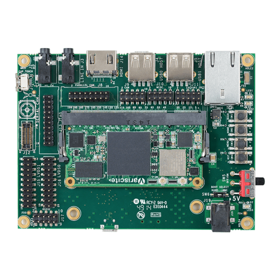
Top side:
1. 5V DC In Jack (J19)
2. Boot select switch (SW6)
3. LVDS0 Header (Secondary Display)
4. RS232 Header
5. LVDS1 Header (Primary Display) (J15)
6. MIPI CSI-2 Camera [optional add-on]
7. JTAG Header
8. Capacitive Touch (J7)
9. VAR-SOM-SOLO/DUAL Connection
10. Headphones Out
11. Line In
12. Parallel Camera Header
13. HDMI
14. CAN Bus Header
15. USB0 Host
VAR-SOM-SOLO/DUAL based on NXP's i.MX6
Evaluation Kit Quick Start Guide
14
15
16
17
18
19
2
1
16. Miscellaneous Header
17. USB1 Host
18. I2C/SPI Header
19. 10/100/1000Mbps Ethernet
20. USER Button1
21. USER Button2
22. USER Button3
23. Reset Button
24. OFF/ON Switch (SW5)
Bottom side:
25. USB Debug (J103)
26. micro SD Card slot (J102)
27. RTC Battery Holder
28. USB0 OTG
29. Resistive Touch
20
21
27
22
23
24
Evaluation Kit initial Setup
1. Carefully remove the 7" LCD and VAR-SOLOCustomBoard board from the
package.
2. Connect the 7" LCD Touch and Display cables to the Evaluation Kit connectors
J7,J15 respectively as shown in the upper left picture.
Note: Display cable connector pins 1,2 (colored in red) should be connected to
J15 pins 1, 2 respectively.
Touch cable – connect cable with metal contacts facing down.
3. Plug the USB type A to micro B cable between the USB debug connector (J103)
and a PC USB port.
4. Plug the wall adapter's pin into the VAR-SOLOCustomBoard
5V power jack (J19) and to a 120VAC~240VAC power source.
28
26
25
29
Advertisement

Related Manuals for Variscite VAR-SOM-SOLO


Summary of Contents for Variscite VAR-SOM-SOLO
- Page 1 VAR-SOM-SOLO/DUAL based on NXP’s i.MX6 Evaluation Kit Quick Start Guide Top side: 16. Miscellaneous Header Evaluation Kit initial Setup 1. 5V DC In Jack (J19) 17. USB1 Host 2. Boot select switch (SW6) 18. I2C/SPI Header 1. Carefully remove the 7” LCD and VAR-SOLOCustomBoard board from the 3.
- Page 2 Evaluation Kit Quick Start Guide Setting the Host PC for Debug Burning Recovery File System Please refer to Variscite’s wiki pages for preparing recovery SD card 1. Download any PC terminal program. Variscite suggests using Putty and burning internal storage (NAND/eMCC) at: 2.
Need help?
Do you have a question about the VAR-SOM-SOLO and is the answer not in the manual?
Questions and answers