Advertisement
Quick Links
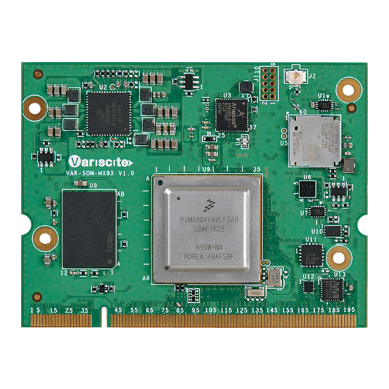
VAR-SOM-MX8X based on NXP i.MX 8X
Evaluation Kit Quick Start Guide
14
13
12
11
Features:
1. Power ON Switch (SW7)
2. 12V DC In Jack (J24)
3. USB Debug (J29)
4. micro SD Card slot (J28)
5. SATA Power (J22)
6. micro SATA Connector (J27)
7. USB 3.0 OTG (J26)
8. USB 2.0 Host (J23)
9. Gigabit Ethernet #0 (J21)
10. Gigabit Ethernet #1 (J20)
11. MIPI-CSI Camera connector [optional] (J19)
12. Miscellaneous Header (J17)
13. HDMI/ Parallel Camera connector [optional] (J13)
14. Mini PCI Express Connector (J15)
15. DSI/QSPI/ADC Header (J3)
16. SOM Connector (J1)
17. LVDS#B Header (J5)
18. LVDS#A Header (J7)
19. Fan Power Connector (J9)
20. Digital Microphone (U1)
21. Resistive Touch (J10)
22. Capacitive Touch (J11)
23. User Buttons (SW1, SW2, SW4)
24. Line-In Connector (J12)
25. Headphones Connector (J14)
26. Boot Select Switch (SW3)
27. SAI/I2C/SPI/CAN Header (J16)
28. Reset Button (SW5)
29. PWR Select Switch (SW6)
15
16
10
9
8
7
17
18
19
21
20
6
5
4
3
30. UART/PWM Header (J18)
31. RTC Battery Holder (JBT1)
Evaluation kit initial Setup
1. Carefully remove the 7" LCD and
Symphony-Board from the package.
2. Connect the 7" LCD Display and Touch
cables to the Evaluation Kit connectors J7,
J11 respectively.
Note:
Display cable – connect the cable with the red
wire on pin 1.
Touch cable – connect the cable with the
metal contacts facing down.
3. Plug the USB type A to micro B cable between
the USB debug connector (J29) and a PC
USB port.
22
23
24
25
26
27
28
29
30
31
2
1
Advertisement

Related Manuals for Variscite VAR-SOM-MX8X


Summary of Contents for Variscite VAR-SOM-MX8X
- Page 1 VAR-SOM-MX8X based on NXP i.MX 8X Evaluation Kit Quick Start Guide Features: 30. UART/PWM Header (J18) 31. RTC Battery Holder (JBT1) 1. Power ON Switch (SW7) Evaluation kit initial Setup 2. 12V DC In Jack (J24) 3. USB Debug (J29) 4.
- Page 2 VAR-SOM-MX8X based on NXP i.MX 8X Evaluation Kit Quick Start Guide Setting the host PC for debug (Re-)Installing the file system to eMMC 1. Download any PC terminal software (e.g. Putty). Please refer to the recovery SD card section in 2.
Need help?
Do you have a question about the VAR-SOM-MX8X and is the answer not in the manual?
Questions and answers