Eaton Digitrip 520 Instructional Leaflet
Trip units for use only in magnum and magnum ds circuit breakers
Hide thumbs
Also See for Digitrip 520:
- Operating manual (42 pages) ,
- Instructions manual (40 pages) ,
- Instructions manual (36 pages)
Table of Contents
Advertisement
Instructional Leaflet IL70C1037H05
Digitrip models 520, 520 i ; and 520M, 520M i ,
520MC, 520MC i trip units for use only in
Magnum and Magnum DS circuit breakers
Effective October 2009
DO NOT ATTEMPT TO INSTALL OR PERFORM
MAINTENANCE ON EQUIPMENT WHILE IT IS
ENERGIZED. DEATH OR SEVERE PERSONAL INJURY
CAN RESULT FROM CONTACT WITH ENERGIZED
EQUIPMENT. ALWAYS VERIFY THAT NO VOLTAGE IS
PRESENT BEFORE PROCEEDING. ALWAYS FOLLOW
SAFETY PROCEDURES. EATON IS NOT LIABLE FOR
THE MISAPPLICATION OR MISINSTALLATION OF
ITS PRODUCTS.
OBSERVE ALL RECOMMENDATIONS, NOTES,
CAUTIONS, AND WARNINGS RELATING TO THE
SAFETY OF PERSONNEL AND EQUIPMENT. OBSERVE
AND COMPLY WITH ALL GENERAL AND LOCAL HEALTH
AND SAFETY LAWS, CODES, AND PROCEDURES.
N
Note:
The recommendations and information contained
herein are based on experience and judgement, but
should not be considered to be all inclusive or to cover
every application or circumstance that may arise.
If you have any questions or need further
information or instructions, please contact
your local Eaton representative or visit
www.eaton.com.
m WARNING
m WARNING
Advertisement
Table of Contents

Related Manuals for Eaton Digitrip 520


Summary of Contents for Eaton Digitrip 520
- Page 1 ENERGIZED. DEATH OR SEVERE PERSONAL INJURY CAN RESULT FROM CONTACT WITH ENERGIZED EQUIPMENT. ALWAYS VERIFY THAT NO VOLTAGE IS PRESENT BEFORE PROCEEDING. ALWAYS FOLLOW SAFETY PROCEDURES. EATON IS NOT LIABLE FOR THE MISAPPLICATION OR MISINSTALLATION OF ITS PRODUCTS. m WARNING...
-
Page 2: Table Of Contents
Ground fault time delay setting ......24 INCOM (Digitrip 520MC models only) ....25 eaton corporation www.eaton.com... -
Page 3: List Of Figures
Figure 43. Digitrip Battery ....... 29 Figure 16. Digitrip 520 LI ....... . 19 Figure 44. -
Page 4: List Of Tables
Table 3. Digitrip Sensing Modes ......11 Table 4. Ground (Earth) Fault Current Settings ....12 eaton corporation www.eaton.com... -
Page 5: Section 1: General Description Of Digitrip Trip Units
In addition to the basic protection circuit breakers. function, the Digitrip 520 family of trip units provides mode of trip information such as: The Magnum Digitrip line of trip units consists of the 520, 520M,... - Page 6 Limited to 1200A; this is only for UL versions, not for IEC models that have “W” in catalog number. Requires Ground Alarm/Power Supply Module (see Section 1). Four Cause of Trip LEDs—L, S, I, G. Making current release is indicated by the Instantaneous LED. 6300A rating for IEC only. Units with ARM in catalog number. eaton corporation www.eaton.com...
- Page 7 Overtemperature trip indication via communications—Long LED shown on front panel. Plug trip cause through communications—INST LED shown on front panel. MCR trip cause through communications—INST LED shown on front panel. High instantaneous trip cause through communications—INST LED on front panel. eaton corporation www.eaton.com...
-
Page 8: Installation And Removal
Insert the rating plug into the cavity on the right-hand side of the trip unit. Align the three pins on the plug with the sockets in the cavity. The plug should fit with a slight insertion force. eaton corporation www.eaton.com... -
Page 9: Wiring
The cover is held in place by two cover screws. Security is ensured by the insertion of a standard meter seal through the holes in both of the cover retention screws. The plexiglass cover has an access hole for the Step and Reset/Battery Test pushbuttons. eaton corporation www.eaton.com... -
Page 10: Ground Alarm/Power Supply Module (520M/Mc Models Only) . 9 Display Feature (520M And 520Mc Only)
Reset button on the Digitrip in order to reset the contacts (see Figurt 5, Note 3). The Digitrip 520, 520M, and 520MC trip units are listed by Underwriters LaboratoriesT, under UL File E52096, for use in Magnum circuit breakers. These same units are recognized by the Canadian Standards AssociationT (CSAT). -
Page 11: Section 2: General Description Of Magnum Circuit Breakers
(shown in Figurt 7 and Figurt 8). If the system neutral is grounded, mechanical tripping parts of the breaker, and external control power but no phase to neutral loads are used, the Digitrip 520 family of is not required. units includes all of the components necessary for ground fault protection. - Page 12 This method is also applicable to double- neutral currents. ended systems where a midpoint grounding electrode is employed. Contact Eaton for more details on this scheme. For this mode of sensing, a single current sensor mounted on the equipment-bonding jumper directly measures the total ground...
- Page 13 Digitrip models 520, 520i; and 520M, 520Mi, Instructional Leaflet IL70C1037H05 520MC, 520MCi trip units for use only in Effective October 2009 Magnum and Magnum DS circuit breakers Source Black K1-2 Trip Digitrip 520 Actuator K1-3 with GF 10:1 K1-9 K1-8 K1-7 K1-6...
- Page 14 Insulation level: 0.6 kV, BIL 10 kV, full-wave Continuous thermal current rating factor: 1.33 at 30°C ambient.,1.0 at 55°C ambient Figurt 9. Digiorip Ntuoral StnsNr Typts (Nr SNurct GrNund StnsNr) Source Black K1-2 Digitrip 520 Trip with GF Actuator K1-3 10:1 K1-9...
- Page 15 The ground current is direct true ground current and is sensed directly via element R A jumper is required on B-6, B-7 (secondary contacts) to program the Digitrip 520 to use element R and input on B-4, B-5 directly for source ground sensing.
- Page 16 520MC, 520MCi trip units for use only in Effective October 2009 Magnum and Magnum DS circuit breakers Source Black Digitrip 520 Trip with GF Actuator Load This scheme uses a large zero sequence CT to magnetically sum the currents and the output is sensed via element R A jumper is required on B-6, B-7 to program the Digitrip to use element R This scheme is not applicable to four-pole breakers.
-
Page 17: Current Sensors (Magnum Standard Frames)
BREAKER. IF THE ZONE INTERLOCKING FUNCTION IS DESIRED FOR IEC signals develop analog voltages across the current viewing resistors. CIRCUIT BREAKERS WITH DIGITRIPS, PLEASE REFER TO EATON FOR The resulting analog voltages are digitized by the CHip chip. APPROPRIATE INSTRUCTIONS ON HOW TO ADJUST THE INTERNAL WIRING HARNESS TO ACTIVATE THE ZONE INTERLOCKING FUNCTION The microcomputer continually digitizes these signals. - Page 18 When zone interlocking is employed, a fault within the Digitrip 520 family on the Short Delay and Ground Fault Protection zone of protection of the breaker will cause the Digitrip 520 family functions (see Figurt 15). The zone interlocking signal is wired via...
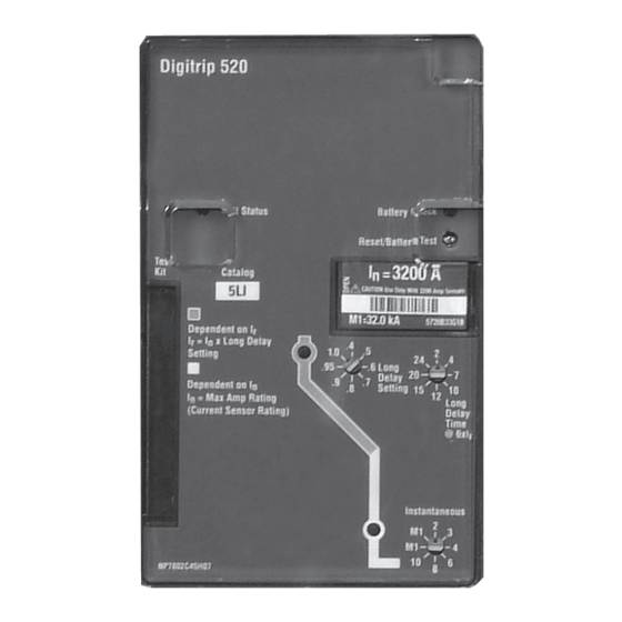
- Page 19 Instructional Leaflet IL70C1037H05 520MC, 520MCi trip units for use only in Effective October 2009 Magnum and Magnum DS circuit breakers Digitrip 520 Figurt 16. Digiorip 520 LI Figurt 18. Digiorip 520 LSIG Figurt 17. Digiorip 520 LSI Figurt 19. Digiorip 520i WLSIG...
- Page 20 520MC, 520MCi trip units for use only in Effective October 2009 Magnum and Magnum DS circuit breakers Figurt 20. Digiorip 520M MLSI Figurt 22. Digiorip 520M MLSIG Figurt 21. Digiorip 520M MLSIA Figurt 23. Digiorip 520Mi MWLSIG eaton corporation www.eaton.com...
- Page 21 @ 6xI r Delay Setting High Load Alarm Short Delay Time * = I t Response Transmit Instantaneous Figurt 26. Digiorip 520MC ARMLSI Figurt 24. Digiorip 520MC CLSI Figurt 25. Digiorip 520MC CWLSIG Figurt 27. Digiorip 520MC ARMLSIG eaton corporation www.eaton.com...
-
Page 22: Section 4: Protection Settings
Figurt 28. Digiorip 520MC ARMLSIA Long Delay Setting l Available Settings 1 x l 0.4, 0.5, 0.6, 0.7, 0.8, 0.9, 0.95, 1.0 In Multiples of Amperes (l Figurt 30. LNng Dtlay Currtno Stooings Figurt 29. Digiorip 520MC ARMWLSIG eaton corporation www.eaton.com... -
Page 23: Long Delay Time Setting
(FLAT) and I The shape selected depends on the type of selective coordination chosen. The I t response curve will provide a longer time delay for current below 8 x I than will the FLAT response curve. eaton corporation www.eaton.com... -
Page 24: Instantaneous Current Setting
2, 3, 4, 5, 6, 8, 10, M1, OFF* In Multiples of Rating Plug Amperes (l M1 value is specified on rating plug. *No OFF on Digitrip 520—5LI style Available Settings 0.1, 0.2, 0.3, Figurt 35. InsoanoantNus Currtno Stooings 0.4, 0.5 Seconds with... -
Page 25: Incom (Digitrip 520Mc Models Only)
FLAT Response When desired, Digitrip 520MC trip units can communicate with a BIM or remote master computer (IBM PC compatible with Eaton CONI card or MINT ) and using PowerNet communication software Version 3.20 or greater (see Figurt 38 for typical wiring.) -
Page 26: Section 5: Test Procedures
Digitrip and the mechanical trip assembly of the breaker. The testing can determine the accuracy of the desired trip settings by performing long delay, short delay, and ground fault functional tests. The Eaton-approved test kit is listed below. Model... -
Page 27: Primary Injection
RETURN THE LTM JUMPER TO ITS ORIGINAL POSITION. Batteries The test kit authorized by Eaton for use with the Digitrip units plugs The functional test kit contains a total of seven 9V batteries. into the test port of the unit and provides a secondary injection test A lithium ion cell is the preferred battery type for BAT A and is that simulates the current transformer. - Page 28 Record the test results on the test form provided with the Primary Disconnect equipment (see Figurt 46). Stabs—When Drawout Suitable Conductors Low Voltage AC Current Source Polarity and Identification Shorting Conductors Figurt 41. CNnntcoiNn Dtoails fNr CNnducoing Singlt-Phast Currtno Ttsos wioh oht Brtaktr RtmNvtd frNm oht Ctll eaton corporation www.eaton.com...
-
Page 29: Section 6: Trip Unit Battery
San Ysidro, CA 92173 cause of trip. 619-661-6620 (www.sanyo.co.jp) Note: A healthy battery is required to fully reset the 4-bit latch chip and associated Cause of Trip LEDs (see Figurt 15). After replacing battery, properly dispose. eaton corporation www.eaton.com... -
Page 30: Section 7: Frame Ratings (Sensor Ratings And Rating Plugs)
For the Digitrip 520 family of trip units, this is implemented by protection equipment. changing the current sensors and the corresponding rating plug. -
Page 31: Section 9: References
ACCOMPLISHED VIA A WIRING HARNESS INTERNAL TO THE CIRCUIT BREAKER. IF THE ZONE INTERLOCKING FUNCTION IS DESIRED FOR IEC CIRCUIT BREAKERS WITH DIGITRIPS, PLEASE CONTACT EATON FOR APPROPRIATE INSTRUCTIONS ON HOW TO ADJUST THE INTERNAL WIRING HARNESS TO ACTIVATE THE ZONE INTERLOCKING FUNCTION ASSOCIATED WITH SECONDARIES B7, B8, AND B9 OF THE CIRCUIT BREAKER. -
Page 32: Section 10: Digitrip 520Mc With Maintenance Mode
ALWAYS VERIFY THAT NO VOLTAGE IS PRESENT BEFORE PROCEEDING. high quality, gold-plated or palladium contact is required in this ALWAYS FOLLOW SAFETY PROCEDURES. EATON IS NOT LIABLE FOR THE application. The blue LED will verify that the function is armed. - Page 33 In addition, the function can also be activated via communications. A blue LED on the Digitrip verifies that Maintenance Mode is armed. The recommended selector switch for this low voltage application is Eaton part number 10250T1333-2E, which includes a contact block rated for logic level and corrosive use.
-
Page 34: Appendix A: Zone Interlocking Examples
–B7—Contact Zone = Zone Out output signal to higher level zone –B9—Contact Zone 3 = Zone In input signal from lower level zone –B8—Contact = Fault at location 2 See Note A4 Figurt 48. Typical ZNnt InotrlNcking eaton corporation www.eaton.com... - Page 35 Magnum and Magnum DS circuit breakers 0.5 Sec. 0.5 Sec. 0.3 Sec. 1N4004 0.1 Sec. 0.1 Sec. 0.1 Sec. 0.1 Sec. 0.1 Sec. Figurt 49. Typical ZNnt InotrlNcking CNnntcoiNns wioh TwN Main Brtaktrs (M1, M2) and a Tit Brtaktr (T) eaton corporation www.eaton.com...
-
Page 36: Appendix B: Troubleshooting Guide
Check for auxiliary power—A14, A15 See Figurt 1 and *Only Digitrip 520MC styles have refer to Section 1 communication features. Check Status LED and Transmit LED Hardware problem Check communications wiring—B1, B2 See Appendix C Missing termination resistor See Figurt 38 eaton corporation www.eaton.com... -
Page 37: Appendix C: Typical Breaker Master Connection Diagram
Digitrip models 520, 520i; and 520M, 520Mi, Instructional Leaflet IL70C1037H05 520MC, 520MCi trip units for use only in Effective October 2009 Magnum and Magnum DS circuit breakers appendix c: typical breaker master connection diagram Figurt 50. Typical Brtaktr Masotr CNnntcoiNn Diagram eaton corporation www.eaton.com... -
Page 38: Appendix D: Modbus Translator Wiring
Magnum Circuit Breaker Control voltage is 120 Vac ± 20% or 24–125 Vdc. Communication cable is Eaton style 2A957805G01 or Belden 9463 cable. The overall network will support up to 32 devices with any addresses from 1–247. Terminating resistor is 121 ohm 1 watt. Use the mMINT switches to insert these terminators at the mMINT device. - Page 39 Digitrip models 520, 520i; and 520M, 520Mi, Instructional Leaflet IL70C1037H05 520MC, 520MCi trip units for use only in Effective October 2009 Magnum and Magnum DS circuit breakers eaton corporation www.eaton.com...
- Page 40 PART OF OR MODIFY ANY CONTRACT BETWEEN THE PARTIES. (“Eaton”) experience and judgment, and may not cover all In no event will Eaton be responsible to the purchaser or user in contingencies. If further information is required, an Eaton sales contract, in tort (including negligence), strict liability, or otherwise office should be consulted.
Need help?
Do you have a question about the Digitrip 520 and is the answer not in the manual?
Questions and answers