Table of Contents
Advertisement
Quick Links
Instructions for the Use, Operation and Maintenance of
Types VCP-TL and VCP-TRL Linear Magnetic Vacuum Circuit Breakers
IB131017EN Effective May 2016
IB131017EN
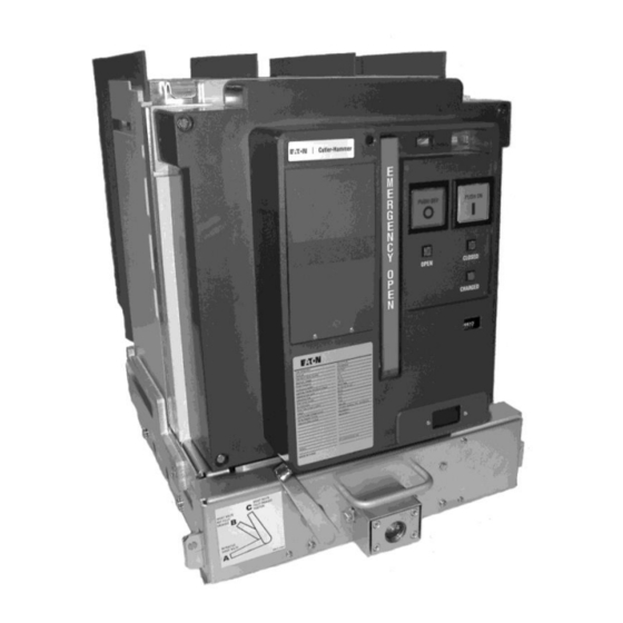
VCP-TL Drawout
(Non-automatic shown)
For more information visit: www.Eaton.com
VCP-TRL Fixed
(shown with optional protective relay installed)
Advertisement
Table of Contents

Related Manuals for Eaton VCP-TL Series


Summary of Contents for Eaton VCP-TL Series
- Page 1 Instructions for the Use, Operation and Maintenance of Types VCP-TL and VCP-TRL Linear Magnetic Vacuum Circuit Breakers IB131017EN Effective May 2016 VCP-TRL Fixed (shown with optional protective relay installed) VCP-TL Drawout (Non-automatic shown) IB131017EN For more information visit: www.Eaton.com...
- Page 3 All possible contingencies which may arise during installation, operation or maintenance, and all details and variations of this equipment do no purport to be covered by these instructions. If further information is desired by purchaser regarding his particular installation, operation or maintenance of particular equipment, contact an EATON representative. IB131017EN For more information visit:...
-
Page 4: Table Of Contents
Accessory Devices ....................................46 5-6.1 Internal Electrical Accessories ............................... 46 5-6.2 Mechanical Accessories ................................. 46 SECTION 6: INSPECTION AND MAINTENANCE Introduction ......................................47 Frequency of Inspection and Maintenance ............................. 47 Vacuum Interrupter Integrity Test ................................47 For more information visit: www.Eaton.com IB131017EN... - Page 5 4-14 VCP-TL Circuit Breaker Shown in Levered Out (DISCONNECT) Position - Correct for Breaker Positioning ........28 4-15 VCP-TL Circuit Breaker Shown in Levered In (CONNECT) Position - Incorrect for Breaker Positioning .......... 28 IB131017EN For more information visit: www.Eaton.com...
- Page 6 Current Sensors and Matching Rating Plugs ..........................45 Auxiliary Switch Contacts Interrupting Capacities ........................... 46 Inspection and Maintenance Procedures ............................48 Test Voltage ....................................49 Typical Resistance Measurements ..............................51 Troubleshooting Guide ................................... 52 For more information visit: www.Eaton.com IB131017EN...
-
Page 7: Section 1: Introduction
SECTION 1: INTRODUCTION 1-1 VCP-TL and VCP-TRL Vacuum Breaker Ratings Refer to Table 1.1 on page 2. The purpose of this book is to provide instructions for unpacking, storage, use, operation and maintenance of The circuit breaker's nameplate provides complete rating information. - Page 8 250A and 1000A. Ratings of 250 and 1000A cover capacitor bank applications from 75 to 1000A. Inrush current and frequency rating = 18 kApk at 2.4 kHz." 1600A VCP-TL Drawout Breaker not available For more information visit: www.Eaton.com IB131017EN...
-
Page 10: Types Vcp-Tl And Vcp-Trl Outlines And Dimensions
Instruction Book Page 4 Effective: May 2016 1-2 Types VCP-TL and VCP-TRL Outlines and Dimensions (Circuit Breakers and Drawout Cassettes) Figure 1-1 VCP-TRL Fixed Breaker 4.76/8.25kV, 600A/800A, 16kA, 60kV BIL Only Outlines in inches (mm] For more information visit: www.Eaton.com IB131017EN... - Page 11 Instruction Book Effective: May 2016 Page 5 Figure 1-2 All VCP-TR Fixed (except 4.76/8.25kV, 600/800A, 16kA, 60kV BIL see Figure 1-1) Outlines in inches [mm] IB131017EN For more information visit: www.Eaton.com...
- Page 12 Instruction Book Page 6 Effective: May 2016 Figure 1-3 VCP-TL Drawout Breaker 4.76/8.25kV Outlines in inches [mm] (Refer to above Applicable Ratings Table) For more information visit: www.Eaton.com IB131017EN...
- Page 13 Instruction Book Effective: May 2016 Page 7 Figure 1-4 VCP-TL Drawout Breaker 4.76/8.25kV Outlines in inches [mm] (Refer to above Applicable Ratings Table) IB131017EN For more information visit: www.Eaton.com...
- Page 14 Instruction Book Page 8 Effective: May 2016 Figure 1-5 VCP-TL Drawout Breaker 8.25/15kV Outlines in inches [mm] (Refer to above Applicable Ratings Table) For more information visit: www.Eaton.com IB131017EN...
- Page 15 Instruction Book Effective: May 2016 Page 9 Figure 1-6 VCP-TL Breaker Cassette Up to 95kV BIL Outlines in inches [mm] (Additional Details Figures 1-7 & 1-8) IB131017EN For more information visit: www.Eaton.com...
- Page 16 Instruction Book Page 10 Effective: May 2016 Figure 1-7 VCP-TL Breaker Cassette 60kV BIL Outlines in inches [mm] (Additional Details Figure 1-6) For more information visit: www.Eaton.com IB131017EN...
- Page 17 Instruction Book Effective: May 2016 Page 11 Figure 1-8 VCP-TL Breaker Cassette 95kV BIL Outlines in inches [mm] (Additional Details Figure 1-6) IB131017EN For more information visit: www.Eaton.com...
-
Page 18: Section 2: Safe Practices
Do not work on a circuit breaker while suspended leading to death, severe personal injury and/or property damage. from a lifting means. Maintenance work should be performed on a properly supported cart or table. For more information visit: www.Eaton.com IB131017EN... -
Page 19: Section 3: Receiving, Handling And Storage
Save all shipping hardware and packaging phase. Record any observed damage for reporting to material for any future shipments of the circuit breaker. the transportation carrier and EATON. All reports should be as specific as possible and include the order number 3-2.2 LIFTING and other applicable nameplate information. -
Page 20: Typical Breaker And Cassette Weights
75 VCP-TRL20 INTENT. 1200 75 VCP-TL20 1600 UNDER NO CIRCUMSTANCES SHOULD 75 VCP-TRL25 ALTERATIONS BE MADE TO EATON SUPPLIED VCP- 1200 T VCP-TR CIRCUIT BREAKERS UNLESS THE 75 VCP-TL25 1600 ALTERATION IS SPECIFICALLY ADDRESSED IN AND PERMITTED BY THIS INSTRUCTION BOOK. - Page 21 69C3104H03 4. Front Cover (Figure 3-9 for details) 69C3056G01 5. Optional Protective Relay 6. Emergency open Handle - 6D33210H11 Figure 3-3 Front and Rear Views VCP-TRL Fixed (4.76 and 8.25kV, 600/800A, 16kA, 60kV BIL) IB131017EN For more information visit: www.Eaton.com...
- Page 22 5. 11 Gauge Grounded (Earth) Steel Barrier 69C3104H03 6. Pole Unit Molding - 70D3001G01 7. Optional Protective Relay 8. Emergency Open Handle - 6D33210H11 Figure 3-4 Front and Rear Views All VCP-TRL Fixed (except 4.76 and 8.25kV, 600/800A, 16kA) For more information visit: www.Eaton.com IB131017EN...
- Page 23 7. Emergency Open Handle - 6D33210H11 20. Integral Wheel - 67A3201H01 21. Shutter Operator - 69C3213H05 22. Primary Disconnect Cup (95kV BIL Only) Figure 3-5 Front and Rear Views VCP-TL Drawout (4.76 and 8.25kV, 600/800A, 16kA, 60kV BIL) IB131017EN For more information visit: www.Eaton.com...
- Page 24 6. Pole Unit Molding - 70D3250G11 7. Optional Protective Relay Location 8. Emergency Open Handle - 6D33210H11 Figure 3-6 Front and Rear Views All VCP-TL Drawout (except 4.76/8.25kV, 600/800A, 16kA, 60kV BIL) See Figure 3-5 For more information visit: www.Eaton.com IB131017EN...
- Page 25 Rej. Pin Kit - 68B3049G01 5. Interlock Lever (Secondary Contact) Interlock Lever - 67A3277H23 6. Grounding (Earthing) Bar 7. Position Switches Figure 3-7 Front and Rear Views Drawout Cassette (For use with 60kV BIL Drawout Breakers Only) IB131017EN For more information visit: www.Eaton.com...
- Page 26 4. Rejection Interlock Pins - 68B3049G01 5. Interlock Lever (Secondary Contact) 67A3277H23 6. Grounding (Earthing) Bar - 69C3266H01 7. Position Switches Figure 3-8 Front and Rear Views Drawout Cassette (For use with all 95kV BIL Drawout Breakers) For more information visit: www.Eaton.com IB131017EN...
- Page 27 Close Indicator - 68B3353H01 10. Front Cover Mounting Hardware 70540AK10R - Flat Washer 70045BB0BG – Bolt 71070CA009 - O Ring 70045BB0A1- Screw 70550AC10R – SPG Washer Figure 3-9 Typical VCP-TL Drawout Breaker Front Cover Details IB131017EN For more information visit: www.Eaton.com...
-
Page 28: Section 4: Installation
Refer to Figures 5-10 to 5-13 for secondary connection details. horizontal) of barriers used with fixed and drawout circuit breakers depend primarily on the circuit breaker rating. Refer to Figures 1-1 to 1-8 for For more information visit: www.Eaton.com IB131017EN... -
Page 29: Installing Drawout Circuit Breaker
If they are not interlocks to insure safe and proper operation. compatible, do not attempt to insert the circuit breaker into the cassette. Contact EATON for assistance if required. Rejection Interlocks Rejection interlocks are steel pins mounted at the bottom of the drawout circuit breaker and in the base tray (floor) of Table 4.1 Cassette Rejection Interlock Pin Locations... -
Page 30: 4-6.2 Circuit Breaker Positioning
OR BODILY INJURY DURING LIFTING AND closed between the CONNECTED and TEST positions. HANDLING. REFER TO PARAGRAPH 4-6.4 FOR Shutter Drive Interlock CIRCUIT BREAK-ER LEVERING DETAILS (FIGURES 4- 14 AND 4-15). The metallic primary safety shutters are independently For more information visit: www.Eaton.com IB131017EN... - Page 31 (Figure 4-6). The lifting slings can now be removed from the circuit breaker. Figure 4-6 Shoot Bolt Handle in Up (Locked) Position IB131017EN For more information visit: www.Eaton.com...
-
Page 32: 4-6.3 Drawout Electrical Interfaces
Shoot Bolts Retracted Fully Inside Cradle the circuit breaker is ready to be inserted into its cassette. Refer to paragraph 4-6.2 for details on positioning of the circuit breaker for insertion into its cassette. For more information visit: www.Eaton.com IB131017EN... - Page 33 Primary connections are made when the spring loaded Interlock Lever finger clusters (disconnects) mounted on the rear of the circuit breaker automatically engage the horizontal stabs rigidly mounted inside the insulating spouts) at the IB131017EN For more information visit: www.Eaton.com...
-
Page 34: 4-6.4 Levering Circuit Breaker
CIRCUIT BREAK-ER POSITIONING DETAILS AND SEE FIGURES 4-14 AND 4-15. Once the VCP-TL circuit breaker is in the TEST position with the secondary umbilical cord properly connected, it is ready to be levered into the CONNECTED position. Using For more information visit: www.Eaton.com IB131017EN... -
Page 35: Cradle Mounted Levering Mechanism
(Figure 4-18). The circuit breaker is shown in the CONNECTED position in Figure 4-19. Figure 4-16 Cradle Mounted Levering Mechanism Figure 4-18 Circuit Breaker Connected as Indicated by Fully Connected Position Label IB131017EN For more information visit: www.Eaton.com... -
Page 36: Typical Circuit Breaker Shown In Connect Position With Secondary Connections Made
(Figure 4-16). Once the drive nut is accessible, engage it breaker in the DISCONNECT position which is necessary with the socket and levering crank. Begin levering the cir- before removing it from the cassette. For more information visit: www.Eaton.com IB131017EN... -
Page 37: Section 5: Description And Operation
(Figures 3-4 and 3-6). unit molding. In addition to high strength structural Other barriers may also be required in keeping with properties, the material used has excellent dielectric paragraph 4-3. characteristics and resists tracking (Figure 5-1). IB131017EN For more information visit: www.Eaton.com... -
Page 38: Typical Vcp-Tl Drawout Breaker Shown (Front Cover Removed)
Instruction Book Page 32 Effective: May 2016 Figure 5-2 Typical VCP-TL Drawout Breaker Shown (Front Cover Removed) For more information visit: www.Eaton.com IB131017EN... -
Page 39: 5-2.1 Contact Erosion Indicator
A great deal of effort has been spent in the design of all EATON vacuum circuit breakers, in order to eliminate the need for field adjustments of wipe or stroke. Refer to paragraph 6-7 for details on visually inspecting contact wipe. -
Page 40: Linear Actuator Mechanism
A dry contact must be used to open or close the circuit breaker remotely. An optional undervolt age release device is available and mounted separately from the circuit breaker. For more information visit: www.Eaton.com IB131017EN... -
Page 41: Connection Diagrams
One end plugs into its Figure 5-6 Secondary Protective Hood matching connector mounted under a protective hood on the front. IB131017EN For more information visit: www.Eaton.com... -
Page 42: Vcp-Trl Non Automatic Connection Diagram
Instruction Book Page 36 Effective: May 2016 Figure 5-7 VCP-TRL Non Automatic Connection Diagram For more information visit: www.Eaton.com IB131017EN... -
Page 43: Vcp-Trl With 520V Trip Unit Connection Diagram
Instruction Book Effective: May 2016 Page 37 Figure 5-8 VCP-TRL with 520V Trip Unit Connection Diagram IB131017EN For more information visit: www.Eaton.com... -
Page 44: Vcp-Trl With 1150V Trip Unit Connection Diagram
Instruction Book Page 38 Effective: May 2016 Figure 5-9 VCP-TRL with 1150V Trip Unit Connection Diagram For more information visit: www.Eaton.com IB131017EN... -
Page 45: Vcp-Tl Non Automatic Connection Diagram
Instruction Book Effective: May 2016 Page 39 Figure 5-10 VCP-TL Non Automatic Connection Diagram IB131017EN For more information visit: www.Eaton.com... -
Page 46: Vcp-Tl With 520V Trip Unit Connection Diagram
Instruction Book Page 40 Effective: May 2016 Figure 5-11 VCP-TL with 520V Trip Unit Connection Diagram For more information visit: www.Eaton.com IB131017EN... -
Page 47: Vcp-Tl With 1150V Trip Unit Connection Diagram
Instruction Book Effective: May 2016 Page 41 Figure 5-12 VCP-TL with 1150V Trip Unit Connection Diagram IB131017EN For more information visit: www.Eaton.com... -
Page 48: Vcp-Tl Drawout Umbilical Cord And Connector Wiring Diagram
Instruction Book Page 42 Effective: May 2016 Figure 5-13 VCP-TL Drawout Umbilical Cord and Connector Wiring Diagram For more information visit: www.Eaton.com IB131017EN... -
Page 49: Top View Secondary Connectors
Instruction Book Effective: May 2016 Page 43 Figure 5-14 Top View Secondary Connectors Figure 5-17 AMP Secondary Wiring Removal Tool (AMP#305183) (C-H#MAMPSEC) IB131017EN For more information visit: www.Eaton.com... - Page 50 Instruction Book Page 44 Effective: May 2016 For more information visit: www.Eaton.com IB131017EN...
-
Page 51: Electronic Tripping System
Table 5.1. The two models (Model 520V Communication and Model 1150V) are not interchangeable in the field. Contact EATON for upgrading to Model 520V or Model 1150V. Three-line, (eight characters per line) LED display. Available control voltages are 24/48Vdc, 12OVac and 24OVac The electronic trip units are self-powered. -
Page 52: 5-5.2 Rating Plug
100:1 and 200:1 tap ratio. Refer to Table 5.2 for a tabulation of the available cur- rent sensor ratings. Table 5.2 Current Sensors and Matching Rating Plugs Current Rating in Amperes 6 3 0 1000 1200 1250 1600 For more information visit: www.Eaton.com IB131017EN... -
Page 53: Accessory Devices
Table 5.3 Auxiliary Switch Contacts Interrupting Capacities Continuous Control Circuit Voltage Current 120 Vac 240 Vac 24 Vdc 48 Vdc 125 Vdc 250 Vdc (amperes) Non-inductive Circuit Interrupting Capacity in Amperes Inductive Circuit Interrupting Capacity In Amperes IB131017EN For more information visit: www.Eaton.com... -
Page 54: Section 6: Inspection And Maintenance
Periodic inspections and associated maintenance are essential for the safe and reliable operation of VCP-TL and VCP-TRL circuit breakers. The inspection frequency and associated maintenance recommended are intended to insure the best possible ongoing service. It For more information visit: www.Eaton.com IB131017EN... - Page 55 Deformation or Excessive No excessive Visual and operational Remove cause and replace parts Wear deformation or wear Manual charging, closing and Manual Operation Smooth operation Correct per troubleshooting chart tripping (Table 6.4) if necessary. IB131017EN For more information visit: www.Eaton.com...
-
Page 56: Contact Erosion
5 wipe condition is observed. milliamperes for one minute to avoid ambiguity due to field emission or leakage currents and the test voltage For more information visit: www.Eaton.com IB131017EN... -
Page 57: Contact Erosion Mark Visible On Stem
Page 51 Figure 6-2 Contact Wipe Inspection Area Figure 6-1 Contact Erosion Mark Visible on Stem Figure 6-4 Unsatisfactory Contact Wipe Condition with Breaker Closed Figure 6-3 Satisfactory Contact Wipe Condition with Breaker Closed IB131017EN For more information visit: www.Eaton.com... -
Page 58: Insulation
Maintain the voltage for one minute. Successful actions. If the problem cannot be resolved with the withstand indicates satisfactory insulation strength of aid of this guide, contact the EATON service center the secondary control circuit. Remove the shooting for more in-depth assistance. - Page 59 Check that interlocks are in correct only) positions and free from obstruc- tions When attempting to close, the circuit Contact EATON Service Center The vacuum interrupter contact wipe breaker opens immediately is incorrectly adjusted Interlock switch is closed (drawout Check that interlocks are in correct...
- Page 60 Verify that emergency open handle is in a vertical position Check all interlock switches for obstructions Controller wiring problem Inspect for loose wires into con- troller Contact EATON Service Center Damaged auxiliary switch or close coil For more information visit: www.Eaton.com IB131017EN...
-
Page 61: Circuit Breaker Lubrication
Instruction Book Effective: May 2016 Page 55 Figure 6-5 Circuit Breaker Lubrication IB131017EN For more information visit: www.Eaton.com... -
Page 62: Drawout Cassette Lubrication
Instruction Book Page 56 Effective: May 2016 Figure 6-6 Drawout Cassette Lubrication For more information visit: www.Eaton.com IB131017EN... -
Page 63: Section 7: Renewal Parts
Describe the item, give the style number, and specify the quantity required. c. Specify the voltage for electrical components. d. Specify the method of shipping desired. Send all orders or correspondence to the nearest EATON sales office. IB131017EN For more information visit: www.Eaton.com... -
Page 64: Mechanism And Related Parts
Description Cat# Mechanical counter MCOUNT (2) Opening Spring and Guide Customer Field Installable Description Style# Blue Opening Spring (High Energy) 67A3142G02 (3) Shock Absorber Customer Field Installable3 Description Style# Shock Absorbor all Breakers 67A3142G01 For more information visit: www.Eaton.com IB131017EN... -
Page 65: Current Path
Instruction Book Effective: May 2016 Page 59 7-4 CURRENT PATH (1) Pole Unit Assembly (VCP-TL and VCP-TRL) (2) 30,000 Operations Maintenance Kit Requires C-HESS (EATON Engineering Services and Systems) Installation Description Style# Maintenance Kit for use when 30,000 operations reached 67A4559G01... - Page 66 Instruction Book Page 60 Effective: May 2016 For more information visit: www.Eaton.com IB131017EN...
- Page 67 (8) Simple Ground and Test Device Customer Field Installable (7) Secondary Umbilical Cord Customer Field Installable Description Style# Simple Ground And Test Device 67A3056G01 Description Style# Secondary umbilical cord 69C3323G01 (Drawn Out circuit breakers only) IB131017EN For more information visit: www.Eaton.com...
-
Page 68: Other Breaker Related Parts
(5) IP54 Cover Kit (Transparent) (4) Non-Automatic Trip Unit Cover Customer Field Installable Customer Field Installable Description Style Description Style Provides protection against dust and 2C14892G01 dripping water (IP54) VCP-T & VCP-TR 2C12812H06 For more information visit: www.Eaton.com IB131017EN... -
Page 69: Trip Unit And Related Parts
Instruction Book Effective: October 2005 Page 62 (6) Spout Boot (2) 520V Trip Unit Kit Requires C-HESS (EATON Engineering Services and Systems) Installation Customer Field Installable Trip Unit Model Power Supply Voltage Style # 520V Trip Unit 67A3154G01 520MCV Trip Unit... - Page 72 Effective: January 2005 Linear Magnetic Vacuum Circuit Breakers Eaton Corporation Cutler- Hammer business unit 1000 Cherrington Parkway Moon Township, PA 15108-4312 tel: 1 -800-525-2000 www.EatonElectrical.com © 2005 Eaton Corporation All Rights Reserved Printed in USA Publication No. IB69C3076H01 (ISI) January 2005...
Need help?
Do you have a question about the VCP-TL Series and is the answer not in the manual?
Questions and answers