Table of Contents
Advertisement
Instructional Leaflet IL8700C39-04
Eaton Digitrip RMS and Digitrip
OPTIM Trip Units with Types DSII
and DSLII Low Voltage Power Circuit
Breakers
Contents
Description
1.0
2.0
3.0
4.0
4.1
4.2
4.3
4.4
4.5
4.6
4.7
5.0
5.1
5.2
5.3
5.4
5.5
5.6
6.0
6.1
6.1.1 Secondary Injection Testing . . . . . . . . . . . . . . . . . . . . . . . . . . . . . . . . . . . . . . . . . . . . . . . . . . . . . . . 15
6.2
6.2.1 Code Requirements . . . . . . . . . . . . . . . . . . . . . . . . . . . . . . . . . . . . . . . . . . . . . . . . . . . . . . . . . . . . . 18
6.2.2 Standards Requirements . . . . . . . . . . . . . . . . . . . . . . . . . . . . . . . . . . . . . . . . . . . . . . . . . . . . . . . . . 18
6.2.3 General Test Instructions . . . . . . . . . . . . . . . . . . . . . . . . . . . . . . . . . . . . . . . . . . . . . . . . . . . . . . . . . 18
7 .0
8.0
8.1
8.2
8.3
Supplementary Information . . . . . . . . . . . . . . . . . . . . . . . . . . . . . . . . . . . . . . . . . . . . . . . . . . . . . . . . 2
Digitrip RMS and Digitrip OPTIM Trip Units . . . . . . . . . . . . . . . . . . . . . . . . . . . . . . . . . . . . . . . . . . . . 2
Rating Plugs . . . . . . . . . . . . . . . . . . . . . . . . . . . . . . . . . . . . . . . . . . . . . . . . . . . . . . . . . . . . . . . . . . . . 3
Digitrip RMS Model Considerations . . . . . . . . . . . . . . . . . . . . . . . . . . . . . . . . . . . . . . . . . . . . . . . . . . 5
Digitrip RMS 510 . . . . . . . . . . . . . . . . . . . . . . . . . . . . . . . . . . . . . . . . . . . . . . . . . . . . . . . . . . . . . . . . 6
Digitrip RMS 610 . . . . . . . . . . . . . . . . . . . . . . . . . . . . . . . . . . . . . . . . . . . . . . . . . . . . . . . . . . . . . . . . 6
Digitrip RMS 810 . . . . . . . . . . . . . . . . . . . . . . . . . . . . . . . . . . . . . . . . . . . . . . . . . . . . . . . . . . . . . . . . 9
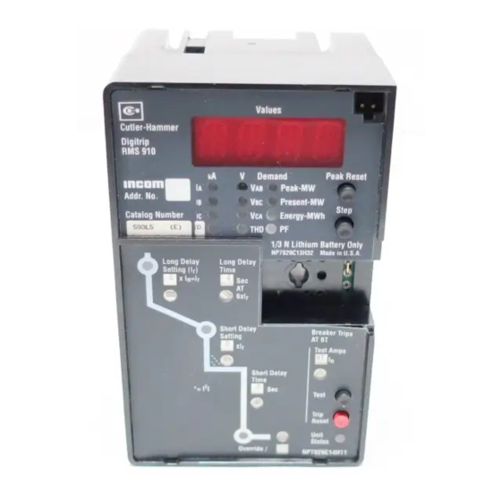
Digitrip RMS 910 . . . . . . . . . . . . . . . . . . . . . . . . . . . . . . . . . . . . . . . . . . . . . . . . . . . . . . . . . . . . . . . 10
Digitrip OPTIM Model Considerations . . . . . . . . . . . . . . . . . . . . . . . . . . . . . . . . . . . . . . . . . . . . . . . 10
Digitrip OPTIM 750 . . . . . . . . . . . . . . . . . . . . . . . . . . . . . . . . . . . . . . . . . . . . . . . . . . . . . . . . . . . . . 10
Digitrip OPTIM 1050. . . . . . . . . . . . . . . . . . . . . . . . . . . . . . . . . . . . . . . . . . . . . . . . . . . . . . . . . . . . . 11
Principle of Operation. . . . . . . . . . . . . . . . . . . . . . . . . . . . . . . . . . . . . . . . . . . . . . . . . . . . . . . . . . . . 12
General . . . . . . . . . . . . . . . . . . . . . . . . . . . . . . . . . . . . . . . . . . . . . . . . . . . . . . . . . . . . . . . . . . . . . . . 12
Digitrip RMS Trip Assembly . . . . . . . . . . . . . . . . . . . . . . . . . . . . . . . . . . . . . . . . . . . . . . . . . . . . . . . 12
Trip Actuator . . . . . . . . . . . . . . . . . . . . . . . . . . . . . . . . . . . . . . . . . . . . . . . . . . . . . . . . . . . . . . . . . . . 12
Ground Fault Protection . . . . . . . . . . . . . . . . . . . . . . . . . . . . . . . . . . . . . . . . . . . . . . . . . . . . . . . . . . 13
Current Sensors . . . . . . . . . . . . . . . . . . . . . . . . . . . . . . . . . . . . . . . . . . . . . . . . . . . . . . . . . . . . . . . . 14
Potential Transformer Module . . . . . . . . . . . . . . . . . . . . . . . . . . . . . . . . . . . . . . . . . . . . . . . . . . . . . 15
Testing . . . . . . . . . . . . . . . . . . . . . . . . . . . . . . . . . . . . . . . . . . . . . . . . . . . . . . . . . . . . . . . . . . . . . . . 15
Functional Field Testing . . . . . . . . . . . . . . . . . . . . . . . . . . . . . . . . . . . . . . . . . . . . . . . . . . . . . . . . . . 15
Performance Testing for Ground Fault Trip Units . . . . . . . . . . . . . . . . . . . . . . . . . . . . . . . . . . . . . . . 18
Record Keeping . . . . . . . . . . . . . . . . . . . . . . . . . . . . . . . . . . . . . . . . . . . . . . . . . . . . . . . . . . . . . . . . 18
Low Voltage Power Circuit Breaker References . . . . . . . . . . . . . . . . . . . . . . . . . . . . . . . . . . . . . . . . 19
Trip Assembly References . . . . . . . . . . . . . . . . . . . . . . . . . . . . . . . . . . . . . . . . . . . . . . . . . . . . . . . . 19
Time-Current Curves . . . . . . . . . . . . . . . . . . . . . . . . . . . . . . . . . . . . . . . . . . . . . . . . . . . . . . . . . . . . 19
Miscellaneous References . . . . . . . . . . . . . . . . . . . . . . . . . . . . . . . . . . . . . . . . . . . . . . . . . . . . . . . . 19
Effective July 2010
Supersedes July 1997
IL8700C39-03
Page
Advertisement
Table of Contents

Related Manuals for Eaton Digitrip RMS Series


Summary of Contents for Eaton Digitrip RMS Series
-
Page 1: Table Of Contents
Effective July 2010 Supersedes July 1997 Instructional Leaflet IL8700C39-04 IL8700C39-03 Eaton Digitrip RMS and Digitrip OPTIM Trip Units with Types DSII and DSLII Low Voltage Power Circuit Breakers Contents Description Page Supplementary Information ............2 Digitrip RMS and Digitrip OPTIM Trip Units . -
Page 2: Supplementary Information
INJury CaN rEsulT frOm CONTaCT wITh ENErgIZED EQuIpmENT. always VErIfy ThaT NO VOlTagE Is prEsENT BEfOrE prOCEEDINg wITh ThE Task, aND always fOllOw gENErally aCCEpTED safETy prOCEDurEs. EaTON Is NOT lIaBlE fOr ThE mIsapplICaTION Or mIsINsTallaTION Of ITs prODuCTs. -
Page 3: Rating Plugs
Hand Held Programmer can establish trip unit addresses. Separate instruction manuals, referenced in Section 8.3, cover all the details associated with the OPTIMizer Hand Held Programmer and the Breaker Interface Module. eaTOn CORPORaTIOn www.eaton.com... - Page 4 Instructional Leaflet IL8700C39-04 Effective July 2010 Figure 2a Typical Digitrip RMS Trip Unit Display Panels Figure 2b Typical Digitrip OPTIM Trip Unit Display Panels eaTOn CORPORaTIOn www.eaton.com...
-
Page 5: Digitrip Rms Model Considerations
Module Field Test Kit Receptacle Receptacle Terminal Block Auxiliary Current Transformer Assembly Potential Trans- former Module (810, 910 and 1050 only) Figure 4 Trip Unit Assembly with Digitrip RMS Trip Unit and Associated Components Installed on Breaker eaTOn CORPORaTIOn www.eaton.com... -
Page 6: Digitrip Rms 510
RMS 510 Trip Unit described in I.L. 29-885, auxiliary current transformers (3 or 4), a stab-in trip unit edge connector and a test terminal block with test receptacles for external field testing mounted in the breaker (Figures 4 and 5). eaTOn CORPORaTIOn www.eaton.com... - Page 7 Remote only - direct to host computer via INCOM/IMPACC. n On AEM denoted by absence of response from addressed breaker. o Supplied only when trip unit is equipped with ground fault protection option. p Requires spring release or electrical operator option. eaTOn CORPORaTIOn www.eaton.com...
- Page 8 Can be disabled with jumper on circuit board. Via OPTIMizer – test and configuration of address and baud rate. BIM (Breaker Interface Module) or direct to host computer. Supplied only when trip unit is equipped with ground fault alarm. eaTOn CORPORaTIOn www.eaton.com...
-
Page 9: Digitrip Rms 810
TraTED IN CONNECTION DIagram 508B508 TO aVOID uNDE- cause of trip LEDs will be maintained by the back-up battery sIrED rEmOTE ClOsINg OpEraTIONs DurINg maINTENaNCE located in the rating plug. pErIODs. alsO prOVIDE aDEQuaTE EQuIpmENT warNINgs fOr NOrmal OpEraTION pErIODs. eaTOn CORPORaTIOn www.eaton.com... -
Page 10: Digitrip Rms 910
Digitrip OPTIM 750 Trip Units provide true rms sensing and utilize a fixed interchangeable rating plug to establish the continuous trip rating of the circuit breaker. Rating plugs are interlocked to prevent use between different circuit breaker types. eaTOn CORPORaTIOn www.eaton.com... -
Page 11: Digitrip Optim 1050
Trip Actuator Typical Trip Unit Typical DSII Type Circuit Breaker Sensors ** Alternate ground locations may be required to meet installation requirements Figure 6 Typical Schematic Diagram of Basic Connections in Tripping System of DSII Circuit Breaker eaTOn CORPORaTIOn www.eaton.com... -
Page 12: Principle Of Operation
The basic Digitrip Trip Assembly, as shown in Figures 4 and 5, includes the following which could vary slightly depending upon the exact model of the Digitrip Trip Unit installed: 1. Digitrip Mounting Assembly 2. Digitrip Trip Unit eaTOn CORPORaTIOn www.eaton.com... -
Page 13: Ground Fault Protection
Table 3 and on the time-current curve. the system. If the system neutral is grounded but the neutral is not car- ried with the phase conductors, the Digitrip Trip Assembly includes all of the equipment necessary for ground fault pro- eaTOn CORPORaTIOn www.eaton.com... -
Page 14: Current Sensors
A complete tabula- 3 are not applicable and the values shown in Table 4 should tion of available current sensors and rating plugs is given in be used. One of the reasons for using the BYZ current eaTOn CORPORaTIOn www.eaton.com... -
Page 15: Potential Transformer Module
DIElECTrIC (Or hIgh pOT Or hIgh VOlTagE) wIThsTaND (Style No. 8779C02G01) TEsTs. rEplaCE ThE plug afTEr all TEsTINg Is COmplETED Auxiliary Power Module aND prIOr TO ClOsINg ThE BrEakEr as pEr ThE EsTaBlIshED (Catalog No. PRTAAMP) OpEraTINg prOCEDurEs. eaTOn CORPORaTIOn www.eaton.com... - Page 16 MENDED. THE TRIPPING OPERATION OF THE CIRCUIT BREAKER WILL CAUSE DISRUPTION OF SERVICE AND POSSIBLY PERSONAL INJURY RESULTING FROM UN- NECESSARY SWITCHING OF CONNECTED EQUIPMENT. Current-Limiting Resistor (if required) Figure 8c Connections for Ground Fault No-Trip Test, with a Three-Wire System eaTOn CORPORaTIOn www.eaton.com...
- Page 17 Ground Fault Test Record should be Retained by Those in Charge of the Building’s Electrical Installation in order to be available to the Authority having Jurisdiction. Test Date Circuit Results Breaker Number Figure 9 Typical Performance Test Record Form eaTOn CORPORaTIOn www.eaton.com...
-
Page 18: Performance Testing For Ground Fault Trip Units
THE BREAKER BEFORE CONDUCTING TESTS. Ideally, sheets of this type should be used and maintained by those personnel in the user’s organization that have the responsibility for protection equipment. eaTOn CORPORaTIOn www.eaton.com... -
Page 19: Low Voltage Power Circuit Breaker References
OPTIMizer Hand Held Programmer Circuit Breakers with Digitrip OPTIM 750 and I.L. 29C893 Breaker Interface Module 1050 Trip Units SC-6275-95 Typical Long Delay I t, Short Delay I t, Types DSII and DSLII rated up to 1200A eaTOn CORPORaTIOn www.eaton.com... - Page 20 Trip Mode Per Unit Setting Setting Short Delay Sec. of Trip Indicated Trip Value Ref. Change Investigated By Shown Made Ground Fault Sec. Date_______________ By____________________________ Figure 10 Typical Trip Function Record Figure 11 Automatic Trip Operation Record eaTOn CORPORaTIOn www.eaton.com...
- Page 21 Instructional Leaflet IL8700C39-04 Effective July 2010 eaTOn CORPORaTIOn www.eaton.com...
- Page 22 Instructional Leaflet IL8700C39-04 Effective July 2010 eaTOn CORPORaTIOn www.eaton.com...
- Page 23 Instructional Leaflet IL8700C39-04 Effective July 2010 eaTOn CORPORaTIOn www.eaton.com...
- Page 24 Disclaimer of warranties and limitation of liability The information, recommendations, descriptions, and safety In no event will Eaton be responsible to the purchaser or notations in this document are based on Eaton Corporation’s user in contract, in tort (including negligence), strict liability, (“Eaton”) experience and judgment, and may not cover all...
Need help?
Do you have a question about the Digitrip RMS Series and is the answer not in the manual?
Questions and answers