
Related Manuals for Eaton VCP-W Series


Summary of Contents for Eaton VCP-W Series
- Page 1 Effective March 2019 Instruction Booklet IB131006EN Supersedes July 2017 Instructions for installation, operation, and maintenance of type VCP-W vacuum circuit breakers...
- Page 2 INSTALLATION OR MAINTENANCE SHOULD BE ATTEMPTED ONLY tact an Eaton representative. BY QUALIFIED PERSONNEL. THIS INSTRUCTION BOOK SHOULD NOT BE CONSIDERED ALL INCLUSIVE REGARDING INSTALLATION OR MAINTENANCE PROCEDURES. IF FURTHER INFORMATION IS REQUIRED, YOU SHOULD CONTACT EATON.
-
Page 3: Table Of Contents
5.9 MOC and TOC switch operations ..........47 EATON www.eaton.com... - Page 4 Figure 25. Lubrication points............49 EATON www.eaton.com...
- Page 5 Table 29. Recommended renewal parts for GB rated breakers ....... . 69 EATON www.eaton.com...
-
Page 6: Introduction
ARE MADE REGARDING THE INFORMATION, RECOMMENDATIONS not allow the industry standard 36 in. (914.4 mm) wide switchgear. AND DESCRIPTIONS CONTAINED HEREIN. In no event will Eaton be From this point on, all circuit breaker elements will be referred to as responsible to the purchaser or user in contract, in tort (including Type VCP-W unless the reference is specific to a particular design. -
Page 7: Type Vcp-W Vacuum Circuit Breaker Element Ratings (Tables 1, 2, 3, 4, 5, And 6)
Non-standard circuit breakers with high close and latch (momentary). Rating for special applications. Consult the Consulting Application Guide CA08104001E sections 1 and 5 for further information. Optional interrupting time of 3 cycles is available. Also 3-second short time current carrying capability. EATON www.eaton.com... -
Page 8: Table 2. (Ansi Standards A ) Type Vcp-W Vacuum Circuit Breaker 27 Kv Rated Symmetrical Current Basis
K=1.0, therefore E = E/K and I = KI. Consult the Consulting Application Guide CA08104001E sections 1 and 5 for further information. Consult the Consulting Application Guide CA08104001E sections 1 and 5 for further information. Optional interrupting time of 3 cycles is available. Tested at 28.5 kV RMS. Tested at 29.5 kV RMS. EATON www.eaton.com... -
Page 9: Table 3. (Ansi Standards) Type Vcp-Wc Extra Capability Vacuum Circuit Breaker 5-27 Kv Rated Symmetrical Current Basis
Close & latch current for 1200 A Type 150 VCP-W 25C is proven at 15 kV. For sealed interrupters at high altitudes, switching voltage is not de-rated. For higher RRRV contact Eaton for more information. Breaker tested to 2700 A single bank switching for momentary load (Thermal derating must consider harmonic content of current waveform). -
Page 10: Rated Symmetrical Current Basis (Standard Ratings)
200,1600(9) 5,000 All circuit breakers are tested to 60 Hz; however, they can also be applied at 50 Hz with no derating. Optional interrupting time of 3 cycles is available. For higher RRRV contact Eaton for more information. EATON www.eaton.com... -
Page 11: Outlines And Dimensions
All Other VCP-W,VCPW-SE & VCP-W K=1<=40 kA 10 (254.00) 12 (304.80) 13.63 (346.20) 29.81 (757.17) 29.44 (747.78) including 50/25C & 150/25C, 1200 A Figure 1. Type VCP-W (K = 1 & MVA), VCPW-SE, and VCP-WC circuit breaker outlines and dimensions in inches (mm). EATON www.eaton.com... -
Page 12: Figure 2. Type Vcpw-Nd Circuit Breaker Outlines And Dimensions In Inches (Mm)
21.38 (543.05) 7.00 7.00 3.69 (177.80) (177.80) (93.73) 19.44 (493.78) 21.96 (557.78) 30.38 (771.65) 12.00 (304.80) 29.44 (747.78) 13.63 (346.202) 2.25 20.88 (57.15) (530.35) 24.63 (625.60) Figure 2. Type VCPW-ND circuit breaker outlines and dimensions in inches (mm). EATON www.eaton.com... -
Page 13: Safe Practices
File claims immedi- shock leading to death, severe personal injury, or property ately with the carrier if damage or loss is detected and notify the damage. nearest Eaton office. BE EXTREMELY CAREFUL while the circuit breaker is on the • 3.3 Handling extension rails. -
Page 14: Tools And Accessories
2.) Functions only in the CONNECT position. circulation to prevent condensation. If the building is not heated, the Eaton strongly recommends use of the TEST and CONNECT position same general rule for heat as for outdoor storage should be applied. -
Page 15: Table 7. Accessories For 36-Inch Wide Breaker Compartments For 29-Inch Frame Breaker
Wheel conversion kit for direct roll-in 68C5010G42 Conversion kit ROF to NON-ROF 1C19779G101 Conversion kit NON- ROF to ROF 1C19779G102 Secondary conversion kit: to convert automatic 1C20335G01 secondary to manual operation Closed door racking guide 1C20339G02 EATON www.eaton.com... -
Page 16: Table 8. Narrow Design Accessories For 26-Inch-Wide Breaker Compartments
240 Vac close and capacitor trip 8346A28G60 Padlock/key provisions with positional interlock 6510C48G01 Includes the padlock assembly plus a positional interlock. This allows for key locking the levering-in cage when the breaker is locked in the DISCONNECT position EATON www.eaton.com... -
Page 17: Table 9. 27 Kv Vcp-W Accessories
Electrical levering-in device Standard accessories include Optional accessories include Portable lifter and lift pan (clockwise): Left and right removable (clockwise): lifting yoke, test Portable lifter extension rails, manual charging cabinet, spin-free levering crank, handle, and levering crank and test jumper EATON www.eaton.com... -
Page 18: Table 10. Simple Manual Ground And Test Devices-Bus Bar Type
VCP-W vacuum circuit breakers Ground and test device (G&TD) accessories: Eaton offers a broad spectrum of manual and electrical G&TDs. All of the manual G&TDs provide access to all the line and load terminals to enable phase checking. Also, they provide the ability to verify operation of the voltage sensing equipment against a live source while verifying that the other connection does not have any voltage present prior to applying the grounds. -
Page 19: Table 13. Simple Electrically Operated Ground And Test Device
3000 A, 250 Vdc or 240 Vac with ROF — 66A5302G49 — 1200/2000/3000 A, 48 Vdc with ROF — — 66A5302G50 1200/2000/3000 A, 125 Vdc or 120 Vac with ROF — — 66A5302G51 1200/2000/3000 A, 250 Vdc or 240 Vac with ROF — — 66A5302G52 EATON www.eaton.com... -
Page 20: Table 14. Simple Electrically Operated Ground And Test Device For Vcp-W Without Key Interlocks
1200/2000 A, ball type—top and bottom studs 66A5296G01 1200/2000 A, ball type—top and bottom studs with factory installed 66A5296G11 wheel kit 27 kV simple manual ground and test device—bus bar type Ball connector Ball type EATON www.eaton.com... -
Page 21: Type Vcp-W Vacuum Circuit Breaker Element Weights (Tables 18, 19, And 20)
460 (209) 1200 480 (218) 2000 500 (227) 270 VCP-W1250(25) 460 (209) 1200 480 (218) 2000 500 (227) 270 VCP-W1600(32) 1200 545 (245) 2000 560 (252) 270VCP-W2000(40) 1200 545 (245) 2000 560 (252) Does not include shipping carton. EATON www.eaton.com... -
Page 22: Table 19. Vcp-W Iec Rated Breaker Weights A
410 (186) 240 VCP-W1 6 462 (210) 1250 484 (220) 2000 506 (230) 240 VCP-W20 462 (210) 1250 484 (220) 2000 506 (230) 40 VCP-W25 462 (210) 1250 484 (220) 2000 506 (230) Does not include shipping carton. EATON www.eaton.com... -
Page 23: Figure 3. Typical Vcp-W Tools And Accessories
Instructions for installation, operation, and maintenance of type Effective March 2019 VCP-W vacuum circuit breakers Figure 3. Typical VCP-W tools and accessories. (Note: products shown for representation only. New products may include design improvements and alternate nameplate configurations.) EATON www.eaton.com... -
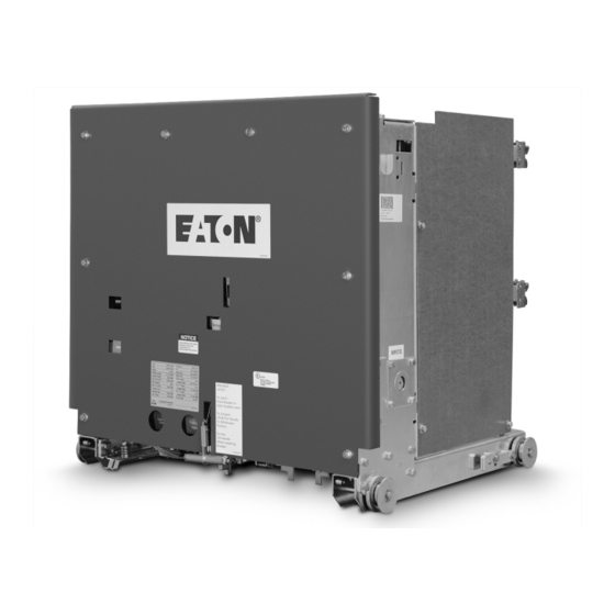
Page 24: Figure 4. Typical Front View Vcp-W Vacuum Circuit Breaker
6. Lifting yoke opening 3. Wheel 7 . Primary disconnect 4. Extension rail interlock 8. Ground contact Figure 4. Typical front view VCP-W vacuum circuit breaker. (See Figure 45 for an example of a roll on the floor wheel kit.) EATON www.eaton.com... -
Page 25: Figure 5. Typical Vcp-W Vacuum Circuit Breaker Element With Front Cover Removed
16. Optional roll on floor wheels 5. Closing cam 11. R. H. closing spring 17 . Position switches 6. Spring release (close coil) assembly 12. Opening spring Figure 5. Typical VCP-W vacuum circuit breaker element with front cover removed. EATON www.eaton.com... -
Page 26: Figure 6. Typical Rear View Vcp-W Vacuum Circuit Breaker Element
1. Vacuum interrupter 2. Phase barrier 3. V-flex current transfer system 4. Direct reading contact erosion indicator 5. Contact loading spring (wipe spring) 6. TOC operator (BPI pan assembly) Figure 6. Typical rear view VCP-W vacuum circuit breaker element. EATON www.eaton.com... -
Page 27: Figure 7. Typical Vcp-W Vacuum Circuit Breaker Front Cover Arrangement
1. Front panel 5. Manual charge socket 2. Nameplate 6. Spring charge/discharge indicator 3. Operation counter 7 . Manual open button 4. Open /closed indicator 8. Manual close button Figure 7. Typical VCP-W vacuum circuit breaker front cover arrangement. EATON www.eaton.com... -
Page 28: Initial Inspection And Installation
TO LEVER THE CIRCUIT BREAKER FROM TEST OR CONNECTED POSITIONS. CORRECT OPERATION OF SOME OF THE INTERLOCKS IS DEPENDENT ON USE OF THE PROVIDED LEVERING-IN CRANK. PERSONAL INJURY OR EQUIPMENT DAMAGE COULD RESULT FROM THE USE OF A TOOL OTHER THAN THE PROPER LEVERING-IN CRANK. EATON www.eaton.com... -
Page 29: Figure 9. Insertion Of The Drawout Extension Rails
BPI label (Figure 12 item 7). Non-BPI pan assembly: the red indicator on the lever- • ing system as shown through the window below the levering-in crank on the front of the levering system (Figure 13, item 7). EATON www.eaton.com... -
Page 30: Figure 11. Front Panel
DISCONNECT/ TEST position. 1. Front panel 5. Manual charge socket 2. Nameplate 6. Spring charge/discharge indicator 3. Operation counter 7 . Manual open button 4. Open /closed indicator 8. Manual close button Figure 11. Front panel. EATON www.eaton.com... -
Page 31: Figure 12. Bpi Pan Assembly
Instruction Booklet IB131006EN Instructions for installation, operation, and maintenance of type Effective March 2019 VCP-W vacuum circuit breakers ote: The legend for Figures 12 and 13 follow Figure 13. Figure 12. BPI pan assembly. EATON www.eaton.com... -
Page 32: Figure 13. Non-Bpi Pan Assembly
11. Coding plates 4. Racking screw 12. Provision for padlocking 5. Moving block 13. Picture frame 6. Slider 14. Breaker rail 7 . Breaker position indication 15. MR2 integral racking provisions (optional) 8. Slider interlocks Figure 13. Non-BPI pan assembly. EATON www.eaton.com... -
Page 33: Circuit Breaker Performance Check
Conclude by closing the circuit breaker. Non-BPI pan assembly: Figure 13 displays the “Z” shaped The circuit breaker is now closed in the TEST position with slider interlock that prevents a closed breaker from being levered springs charged. out of the cell. EATON www.eaton.com... -
Page 34: Circuit Breaker/Structure Interfacing
Figure 15. 2. Secondary disconnect 3. Close floor tripper 4. Levering latch 5. Trip floor tripper 6. Code plates 7 . MOC operator 8. TOC operator (Non-BPI pan assembly Figure 15. Typical VCP-W circuit breaker bottom view. EATON www.eaton.com... -
Page 35: Figure 16. Pulling Secondary Disconnect Cage To Engage Secondaries In Test Position
Lever the circuit breaker towards the CONNECTED position. As move the circuit breaker from the CONNECTED to the TEST posi- the circuit breaker moves, protective compartment shutters will tion, the circuit breaker will do one of the following. automatically begin to open uncovering fixed primary contacts. EATON www.eaton.com... -
Page 36: Description And Operation
THE INTERFACE CHECKS OUTLINED IN THIS MANUAL AND THE MANUAL PROVIDED WITH THE ASSEMBLY STRUCTURE ARE INTENDED TO VERIFY SAFE AND PROPER OPERATION. IF OBSERVED CONDITIONS ARE NOT AS DESCRIBED, CONTACT EATON FOR ASSISTANCE. Figure 18. Typical VCP-W rear view showing vacuum interrupters and current carrying system. -
Page 37: Vacuum Interrupter
If contact erosion reaches 1/8 in. (3.18 mm), the interrupter must be replaced. A horizontal colored or machined contact erosion indicator mark is located on the moving stem of the interrupter (Figures 27 and 28). EATON www.eaton.com... -
Page 38: Stored Energy Mechanism
Breaker element closed, closing springs charged. 75 VCP-W40 1200 2000 3000 2 (INNER) 75 VCP-W50 1200 2 (INNER), 2 in cell 2000 2 (INNER), 2 in cell 3000 2 (INNER), 2 in cell 150 VCP-W25 1200 2 (INNER) 2000 3000 2 (INNER) EATON www.eaton.com... -
Page 39: Figure 20. Closing Cam And Trip Linkage
6. Shunt trip coil 10. Main link roller 3. Banana link 7 . Cam shaft 11. Trip bar “D” shaft 4. Trip latch 8. Closing cam 12. Trip latch reset spring Figure 20. Closing cam and trip linkage. EATON www.eaton.com... -
Page 40: Figure 21. Charging Schematic
4. Spring crank 11. Ratchet wheel 5. Closing spring 12. Holding pawl 6. Closing spring fixed end 13. Spring release (close) clapper 7 . Spring release (close) coil 14. Spring release latch (close roller) Figure 21. Charging schematic. EATON www.eaton.com... -
Page 41: Charging
5.3.5 Trip free operation When the manual trip button is held depressed, any attempt to close the circuit breaker results in the discharge of the closing springs without any movement of the pole shaft or vacuum interrupter stem. EATON www.eaton.com... -
Page 42: Figure 22. Typical Vcp-W Dc And Ac Control Schemes
Effective March 2019 VCP-W vacuum circuit breakers Figure 22. Typical VCP-W DC and AC control schemes. (Dashed lines represent customer wiring and components. This is just one of the many wiring methods that can be used to control the breaker.) EATON www.eaton.com... -
Page 43: Figure 23. 15 Kv Vcp-Wxc 63 Ka 1200-3000 A Special Power Plant Breakers
Figure 23. 15 kV VCP-WXC 63 kA 1200-3000 A special power plant breakers, styles: 4A35390G10, 4A35391G10, 4A35392G10 - DC control scheme and diagram. (Dashed lines represent customer wiring and components.) ote: This differs from the standard VCP-W breaker with the addition of a third motor-cut-off switch and other wiring changes. EATON www.eaton.com... -
Page 44: Figure 23. 5 Kv Vcp-Wxc 63 Ka 1200-3000 A Special Power Plant Breakers
ARE CONFIGURED FOR POWER PLANT SPECIFIC APPLICATIONS ONLY. POTENTIALLY SEVERE UNINTENDED CONSEQUENCES COULD RESULT IF THESE DEVICES ARE MISAPPLIED. PLEASE CONSULT AN EATON APPLICA- TION ENGINEER FOR ANY QUESTIONS BEFORE USE OF THESE PRODUCTS. Figure 23 - 5 kV VCP-WXC 63 kA 1200-3000 A special power plant breakers, styles: 4A35390G10, 4A35391G10, 4A35392G10 - DC control scheme and diagram (continued). -
Page 45: Timing
Vac and 240 Vac options. If needed, continuous trip coil monitoring is available. Also there is an option to have a second shunt trip which can be rated at a different voltage other than the voltage specified for the primary shunt trip. EATON www.eaton.com... -
Page 46: Figure 24. 15 Kv Under-Voltage Trip Device Configuration
1. Moving clapper 5. Trip D shaft lever 2. Stationary yoke 6. Slotted link 3. UV trip device coil 7 . Pole shaft lever 4. Extension springs 8. Reset lever Figure 24. 15 kV under-voltage trip device configuration. EATON www.eaton.com... -
Page 47: Interlocks And Interfacing
(Figure 15). It operates the circuit breakers, the device is a racking screw, racking nut, and TOC switch as the circuit breaker moves to the CONNECTED posi- moving block. tion in the switchgear cell. EATON www.eaton.com... -
Page 48: Inspection, Maintenance, And Troubleshooting
6.2 Frequency of inspection and maintenance In addition to the instructions in this instruction book, Eaton has Periodic inspections and associated maintenance are essential to created a visual tool to assist maintenance personnel. Contact... -
Page 49: General Torque Guidelines
TORQUING WILL NOT PROVIDE THE PROPER CLAMPING FORCE AND MAY EVENTUALLY WORK LOOSE. 1 Apply one drop of mineral oil at locations shown. Figure 25. Lubrication points. X-washer Figure 26. 50 VCP-W 63 - 63 kA pole unit. EATON www.eaton.com... -
Page 50: Inspection And Maintenance Procedures
Remove cause and replace parts. wear Manual ooperation Smooth operation Manual charging, closing and Correct per troubleshooting chart if tripping necessary. CloSure test 0.6 inch over-travel CloSure Test (6.9.1) If < 0.6, contact your local Eaton Sales and Service Center. EATON www.eaton.com... -
Page 51: Vacuum Interrupter Integrity Test
It is recommended that the equipment be capable of delivering 25 milliamperes for one minute. ONLY AC HIGH POTENTIAL TESTS ARE RECOMMENDED. EATON DOES NOT RECOMMEND DC POWER FREQUENCY WITHSTAND VOLTAGE TEST. Table 24. Test voltage (insulation and vacuum integrity). -
Page 52: Figure 27 . Vacuum Interrupter Showing Contact Erosion Indicator With Breaker Open
– “Wipe” satisfactory. – “Wipe” satisfactory. Indicator not visible Red or gray indicator not visible “T” shape indicator not visible – “Wipe” unsatisfactory. – “Wipe” unsatisfactory. – “Wipe” unsatisfactory. Figure 29. Wipe indication procedure (performed only with the breaker closed). EATON www.eaton.com... -
Page 53: Insulation
The recommendations and information contained herein are based Table 25. Typical resistance measurements. on Eaton experience and judgment, but should not be considered to be all-inclusive or covering every application or circumstance which Rated continuous current... -
Page 54: Figure 30. Starting Tape At The Bottom Of The Cam
Figures 30, 31, and 32). 5. Mount the transparent CloSure test tool with two bolts and washers. Refer to Figures 43, 44, and Table 26 for appropriate mounting holes. Hand tighten the bolts (Figures 33, 34, 43, and 44). EATON www.eaton.com... -
Page 55: Figure 35. Manually Charging The Closing Springs
(Figures 37 , 43, and 39). Figure 38. Move marker 15° to the right. Figure 36. Manually closing the circuit breaker with the marker in hole “C” . Figure 39. Move marker 15° to the left. EATON www.eaton.com... -
Page 56: Figure 40. Remove Marked Masking Tape From The Cam
Figure 41. Place the tape on the right side panel of the breaker. 8.0 to10 in. (203.20 to 254.00 mm) Figure 42. Illustrative testing tape sample. Figure 44. Typical circuit breaker front view with CloSure tool attached (approximate mechanism chassis width). EATON www.eaton.com... -
Page 57: Mechanism Lubrication
2. Dust particles are less likely to stick to blue wax as opposed to DHP-VR grease. Dirty grease can be a poor conductor. 3. The blue additive is added by Eaton to provide the ability to VCPW-ND 20/21 perform visual checks of the breaker finger cluster engagement VCP-W, on the switchgear stabs. -
Page 58: Troubleshooting Chart
It is important to learn the field failures. To aid in this process, it is recommended that IEEE Std C37 .10 (section A.1) and the reporting form IEEE Std 1325 be considered for reporting the breaker failure event to EATON. EATON www.eaton.com... -
Page 59: Renewal Parts
4. Specify the voltage for electrical components. to Tables 27 and 28 for guidance. 5. Specify the method of shipping desired. 6. Send all orders or correspondence to the nearest Eaton sales office. Table 27. Recommended renewal parts for ANSI rated breakers (continued next page). - Page 60 270/32, 1200 A-50 kA 8299A05H01 270/32, 1200 A-50 kA 8299A02H01 270/40, 1200 A-64 kA 8299A05H01 270/40, 2000 A-64 kA 8299A02H01 Primary disconnects Up to 15 kV, 1200 A 508B022G01 508B022G01 502A851G02 Up to 15 kV, 2000 A 508B012G01 508B012G014 EATON www.eaton.com...
- Page 61 1C94385G02 27 kV - blue springs 691C241G01 27 kV - black springs 1C94715G01 Tie bars Up to 15 kV 3619A09H01 691C271H01 3619A09H01 63 kA only 1C94404H01 27 kV (up to 25 kA) 691C223H01 27 kV (31.5/40 kA) 1C94707H01 EATON www.eaton.com...
- Page 62 48 Vdc 8064A19G01 8064A19G01 8064A19G01 125 Vdc 8064A19G02 8064A19G02 8064A19G02 250 Vdc 8064A19G03 8064A19G03 8064A19G03 120 AC 8064A19G09 8064A19G09 8064A19G09 240 AC 8064A19G10 8064A19G10 8064A19G10 Motor cut off switch 699B199G01 699B199G04 699B199G01 Latch check switch 699B147G01 699B147H04 699B147G01 EATON www.eaton.com...
- Page 63 Front panel (w/o ESCN) 3000 A, 350/1000 MVA, 63 kA 691C655H01 691C655H01 27 kV 691C214H01 All others 691C192H03 691C192H03 691C253H01 Breaker wheel (H03 and 3617A99H03 3617A99H03 8237A50H01 H04) = 1 wheel 3617A99H04 3617A99H04 Fastener kit 8061A01G01 8061A01G01 8061A01G01 EATON www.eaton.com...
- Page 64 8297A34H16 150/63C, 1200 A 8297A35H11 150/63C, 2000 A 8297A35H12 150/63C, 3000 A 8297A35H13 270/25C, 1200 A 8297A36H01 270/25C, 1600 A 8297A36H02 270/32C, 1200 A 8297A36H03 270/32C, 1 600 A 8297A36H04 270/40C, 1200 A 8297A36H05 270/40C, 1600 A 8297A36H06 EATON www.eaton.com...
-
Page 65: Table 28. Recommended Renewal Parts For Iec Rated Breakers
120/25-630 A 8299A01H15 120/25-1250 A 8299A01H16 120/25-2000 A 8299A01H17 120/32-1250 A 8299A01H18 120/32-2000 A 8299A01H19 120/40-1250 A 8299A01H20 120/40-2000 A 8299A01H21 175/25-1250 A 8299A01H22 175/25-2000 A 8299A01H23 175/32-1250 A 8299A01H24 175/32-2000 A 8299A01H25 175/40-1250 A 8299A01H26 175/40-1250 A 8299A01H27 EATON www.eaton.com... - Page 66 Up to 175/40-1250 A 699B104G01 Up to 175/40-2000 A 508B012G01 240/25-630 A 699B352G01 240/25-1250 A 699B352G01 240/25-2000 A 699B352G02 Phase barrier Up to 175/40 691C176H04 691C218H01 240/25 Push rod assemblies Up to 175/40-white springs 691C650G01 Up to 175/40-blue springs 691C651G01 EATON www.eaton.com...
- Page 67 250 Vdc 3759A74G05 8237A27H05 120 Vac 3759A74G01 8237A27H01 240 Vac 3759A74G02 8237A27H02 Shunt trip coils 24 Vdc 3759A76G04 3759A76G14 48 Vdc 3759A76G01 3759A76G11 125 Vdc/120 Vac cap trip 3759A76G02 3759A76G12 250 Vdc/240 Vac cap trip 3759A76G03 3759A76G 13 EATON www.eaton.com...
- Page 68 Motor cut off switch 699B199G01 699B199G04 Latch check switch 699B147G01 699B147H04 Position switch 1 8064A03G01 699B147H01 Position switch 2 3759A93G01 3759A93H02 Auxiliary switch 698B822H01 5697B02G01 Trip D-shaft 694C638G02 694C638G02 Main link & 3A75675G01 3A75675G01 trip latch Ground contact assembly 691C506G01 691C506G01 EATON www.eaton.com...
-
Page 69: Table 29. Recommended Renewal Parts For Gb Rated Breakers
250 Vdc 691C274G03 691C274G03 120 Vac 691C274G04 691C274G04 240 Vac 691C274G05 691C274G05 CloSure test 6352C58G01 6352C58G01 Table 29. Recommended renewal parts for GB rated breakers. Style Number Line no. Description VCP-W W-VACW W-VACX Qty. 150VCP-WGC50 1200 A 8297A36G28 EATON www.eaton.com... -
Page 70: Optional Accessories
180 degrees from the picture shown above to align better with the 8.1 Optional factory installed roll-on-floor wheel kit center of gravity. Eaton (29” wide frame) breakers: 8.2 Optional automatic/manual hybrid secondary for BPI pan assembly Rated at 5, 15, or 27 kV - can be ordered with the “optional”... -
Page 71: Optional 3,000 A Ball Screw Drive For Bpi Pan Assembly
63 kA or 3,000 A breaker. If the customer is using a MR2 system to lever in the breakers, then this system is not required. This optional accessory is style number 1C20376G01. EATON www.eaton.com... - Page 72 THIS DOCUMENT SHALL NOT BECOME PART OF OR MODIFY ANY CONTRACT BETWEEN THE PARTIES. In no event will Eaton be responsible to the purchaser or user in contract, in tort (including negligence), strict liability or other-wise for any special, indirect, incidental or consequential damage or loss...
Need help?
Do you have a question about the VCP-W Series and is the answer not in the manual?
Questions and answers