
Related Manuals for Eaton VCP-W


Summary of Contents for Eaton VCP-W
- Page 1 IB131006EN Instructions for Installation, Operation and Maintenance of Type VCP-W Vacuum Circuit Breakers Effective 07/2017 Courtesy of NationalSwitchgear.com...
- Page 2 A l l possible contingencies which may arise during installation, operation or maintenance, and all details and variations of this equipment do not purport to be covered by these instructions. If further information is desired by purchaser regarding his particular installation, operation or maintenance of particular equipment, contact an Eaton representative. Effective 07/2017 Courtesy of NationalSwitchgear.com...
-
Page 3: Table Of Contents
1-1.1 Warranty and Liability Information ...................... 1 1-1.2 Safety Precautions ..........................1 General Information ............................. 1 Type VCP-W Vacuum Circuit Breaker Element Ratings (Tables 1.1, 1.2, 1.3, 1.4, 1.5, 1.6,1.7,1.8 & 1.9) 2 Outlines and Dimensions ..........................8 SECTION 2: SAFE PRACTICES Recommendations ............................ - Page 4 IB131006EN P a g e v SECTION 5: DESCRIPTION AND OPERATION Introduction ..............................25 Interrupter Assembly ..........................25 5-2.1 Vacuum Interrupter ........................25 5-2.2 Contact Erosion Indication ....................... 26 5-2.3 “T” Cutout Loading Spring Indicator ..................26 5-2.4 Contact Wipe and Stroke ......................26 5-2.5 Phase Barrier ...........................
- Page 5 Figure Title Page Type VCP-W and Type VCPW-SE Circuit Breaker Outlines and Dimensions in inches ......8 Type VCPW-ND Circuit Breaker Outlines and Dimensions in inches............9 Typical VCP-W Tools and Accessories ....................14 Typical Front View VCP-W Vacuum Circuit Breaker Element ..............15 Typical VCP-W Vacuum Circuit Breaker Element with Front Cover Removed ........
- Page 6 Type VCP-W Vacuum Circuit Breaker 27 kV Rated Symmetrical Current Basis ........3 Type VCP-W Extra Capability Vacuum Circuit Breaker 5-15 kV Rated Symmetrical Current Basis ..3 Type VCP-W Generator Vacuum Circuit Breaker 5-15 kV Rated Symmetrical Current Basis ....4 Type VCP-W Generator Vacuum Circuit Breaker Through 17.5 kV Rated Symmetrical Current Basis ..
-
Page 7: Section 1: Introduction
THE WARNINGS AND CAUTIONS INCLUDED AS all circuit breaker elements will be referred to as Type PART OF THE PROCEDURAL STEPS IN THIS VCP-W unless the reference is specific to a particular DOCUMENT ARE FOR PERSONNEL SAFETY AND design PROTECTION OF EQUIPMENT FROM DAMAGE. AN... -
Page 8: Type Vcp-W Vacuum Circuit Breaker Element Ratings (Tables 1.1, 1.2, 1.3, 1.4, 1.5, 1.6,1.7,1.8 & 1.9)
STRICTLY ADHERED TO. BOOK ARE DESIGNED AND TESTED TO OPERATE 1-3 TYPE VCP-W VACUUM CIRCUIT BREAKER ELEMENT RATINGS (TABLES 1.1, 1.2, 1.3, 1.4, 1.5, 1.6 AND 1.7) 1.1 (ANSI Standards) Type VCP-W Vacuum Circuit Breaker Through 15 kV Rated Symmetrical Current Basis... - Page 9 IB131006EN P a g e 3 Table 1.2 (ANSI Standards) Type VCP-W Vacuum Circuit Breaker 27 kV Rated Symmetrical Current Basis Identification Rated Values Circuit Nominal Nominal Inter- Permis- Breaker Voltage 3-Phase Voltage Insulation Level Current rupting sible Transient Recovery Voltage Current Values...
- Page 10 150VCP-WG63 15.0 1200 15.0 2000 3000 Table 1.5 (IEC-56 Standards ) Type VCP-W Vacuum Circuit Breaker Through 17.5 kV Rated Symmetrical Current Basis Identification Rated values Circuit Voltage Class Normal Current Short circuit 3 Second Short Time Short Circuit...
- Page 11 IB131006EN P a g e 5 Table 1.6 (IEC-56 Standards ) Type VCP-W Vacuum Circuit Breaker Through 24 kV Rated Symmetrical Current Basis Identification Rated values Circuit Voltage Normal Current Short circuit Insulation level Transient Recovery Voltage Short Short...
- Page 12 IB131006EN P a g e 6 Table 1.8 (ANSI Standards) Type VCP-W ( K=1) Vacuum Circuit Breaker Through 15 kV Rated Symmetrical Current Basis (Standard Ratings) Identification Rated Values Circuit Nominal Inter- Permis- Maximum Voltage Insulation Level Current Current Values...
- Page 13 1B131006EN P a g e 7 Table 1.9 (ANSI Standards) Type VCP-WXC Circuit Breaker Through 15 kV Rated Symmetrical Current Basis (Standard Ratings) See Page 40 (Figure 5-5A) for Control Schemes and Diagram that apply to this breaker. This Breaker differs from The Standard Breaker with the addition of a third motor cut-off switch and addition of two wires.
-
Page 14: Outlines And Dimensions
All Other VCP-W,VCPW-SE & VCP-W K=1<=40kA 13.63 29.81 29.44 including 50/25C & 150/75C, 1200A Figure 1-1 Type VCP-W, VCP-W K=1 & VCPW-SE Circuit Breaker Outlines and Dimensions in inches E f f ec t iv e 0 7/ 2 0 1 7 Courtesy of NationalSwitchgear.com... - Page 15 1B131006EN P a g e 9 Figure 1-2 Type VCPW-ND Circuit Breaker Outlines and Dimensions in inches E f f ec t iv e 0 7/ 2 0 1 7 Courtesy of NationalSwitchgear.com...
-
Page 16: Section 2: Safe Practices
2-1 RECOMMENDATIONS firmly hold the circuit breaker on the extension rails while performing such activities as charging, closing Type VCP-W Vacuum Circuit Breaker Elements are and tripping. Carelessness could cause the circuit equipped with high speed, high energy operating breaker to fall from the rails resulting in personal injury mechanisms. -
Page 17: Section 3: Receiving, Handling And Storage
Type VCP-W Vacuum Circuit Breaker Elements are hole toward the interrupters. Once the lifting yoke is subjected to complete factory production tests and securely seated in the holes, the breaker element can inspection before being packed. -
Page 18: Tools And Accessories
3000 525 (238) 150VCP-W500 1200 350 (159) Rail Clamps: Used to secure breaker to extension rails 150VCPW-SE500 2000 410 (186) (Style 6511C83G11 for VCP-W and VCP-SE) and (Style 3000 525 (238) 6511C83G02 for VCPW-ND). 150VCP-W750 1200 350 (159) 150VCPW-SE750 2000... - Page 19 T able 3.2 V CP-W IEC Rated Break e r W eights T able 3.3 V CP-W K= 1 Breaker W ei g hts Normal Rating Amperes Lbs. (kg) Rating Current Lbs. (kg) Amperes 150 VCP-W 25 1200 350 (159) 350 (159) 36VCPW-ND25 2000 375 (170) 1250 350 (159) 3000...
- Page 20 IB131006EN Page 14 Figure 3-1 Typical VCP-W Tools and Accessories (Note: Products shown for representation only. New products may include design improvements and alternate nameplate configurations. E f f ec t iv e 0 7/ 2 0 1 7 Courtesy of NationalSwitchgear.com...
- Page 21 4. EXTENSION RAIL INTERLOCK 8. GROUND CONTACT Newer model Breakers may not have the Figure 3-2 Typical Front View VCP-W Vacuum Circuit Breaker ( escutcheon as shown) E f f ec t iv e 0 7/ 2 0 1 7...
- Page 22 IB131006EN Page 16 Figure 3-3 Typical VCP-W Vacuum Circuit Breaker Element with Front Cover Removed E f f ec t iv e 0 7/ 2 0 1 7 Courtesy of NationalSwitchgear.com...
- Page 23 IB131006EN Page 17 Figure 3-4 Typical Rear View VCP-W Vacuum Circuit Breaker Element E f f ec t iv e 0 7/ 2 0 1 7 Courtesy of NationalSwitchgear.com...
- Page 24 7. MANUAL OPEN BUTTON 4. OPEN/CLOSED INDICATOR 8. MANUAL CLOSE BUTTON 5. MANUAL CHARGE SOCKET Figure 3-5 Typical VCP-W Vacuum Circuit Breaker Front Cover Arrangement E f f ec t iv e 0 7/ 2 0 1 7 Courtesy of NationalSwitchgear.com...
-
Page 25: Section 4: Initial Inspection And Installation
Remove the maintenance tool. Close and trip the circuit breaker. Repeat several times. 4-3 VACUUM INTERRUPTER INTEGRITY Figure 4-1 Type VCP-W Circuit Breaker Manual Charging Handle in Use Using a dry, lint free cloth or paper towel, clean all the accessible insulating surfaces of the pole units. -
Page 26: Electrical Operation Check
IB131006EN Page 20 4-8 ELECTRICAL OPERATION CHECK 2. In order to insert or remove a breaker a set of After having completed all previous checks and tests, the extension rails must be inserted into the left hand circuit breaker is ready to be operated electrically. It is and right hand rail assemblies .This is achieved by preferred that this check be made with the circuit breaker inserting the appropriate rail, identified with a... - Page 27 IB131006EN Page 21 without the extension rails in place. Checking pan operation: CAUTION A. To operate the breaker at this time (test position mode), it is necessary to connect the secondary harness with the breaker. DO NOT USE ANY TOOL OTHER THAN THE LEVERING-IN CRANK PROVIDED TO LEVER THE Manual secondary: For a manually engaged secondary CIRCUIT BREAKER FROM TEST OR CONNECTED...
- Page 28 IB131006EN Page 22 position. E f f ec t iv e 0 7/ 2 0 1 7 Courtesy of NationalSwitchgear.com...
- Page 29 IB131006EN Page 23 Figure 4-2C Pan Assembly 1. FRONT PANEL 6. SPRING CHARGED/DISCHARGED INDICATOR 2. NAMEPLATE 7. MANUAL OPEN BUTTON 3. OPERATION COUNTER 8. MANUAL CLOSE BUTTON 4. OPEN/CLOSED INDICATOR 5. MANUAL CHARGE SOCKET E f f ec t iv e 0 7/ 2 0 1 7 Courtesy of NationalSwitchgear.com...
- Page 30 IB131006EN Page 24 1. Ground Contacts 11. Coding Plates 2. Levering System 12. Provision for Padlocking 3. Automatic Secondary 13. Metal Framework 4. Racking Screw 14. Breaker Rail 5. Moving Block 15. MR2 Integral Racking Provisions 6. Slider 7. Breaker Position Indication 8.
- Page 31 IB131006EN Page 25 Breaker pan assembly Callout descriptions for Figure 4-2D 8. Slider interlocks prevent removing a closed breaker. 1. Grounding contact grounds the breaker in positions. 9. The breaker MOC (mechanism-operated 2. The levering system prevents removal of the compartment) switch is an assembly of switches breaker in any position other than the Disconnect that is operated by a lever on the breaker...
-
Page 32: 4-8.2 Operation Check Performance
Conclude by closing the circuit breaker. The circuit breaker is now closed in the TEST position with springs charged. Figure 4-4 Typical VCP-W Circuit Breaker Bottom View E f f ec t iv e 0 7/ 2 0 1 7 Courtesy of NationalSwitchgear.com... -
Page 33: Circuit Breaker/Structure Interfacing
Code plates do not block out control voltage or AGE DUE TO THE HAZARDOUS VOLTAGE PRESENT. scheme incompatibility. Type VCP-W Circuit Breakers are supplied with a series of Maintenance Interlock interlocks to insure safe and proper interfacing between the circuit breaker and its compartment. Specific interlocks... - Page 34 If also operate once the CONNECTED position is observed conditions are not as described, contact Eaton for assistance. E f f ec t iv e 0 7/ 2 0 1 7 Courtesy of NationalSwitchgear.com...
-
Page 35: Section 5: Description And Operation
5-2.1 VACUUM INTERRUPTER The rest of this section describes the overall operation of the VCP-W circuit breaker as well as the function and Type VCP-W Vacuum Circuit Breakers utilize vacuum operation of all major sub-assemblies and/or parts. Keep interrupters for interruption and switching functions. -
Page 36: 5-2.2 Contact Erosion Indication
A great deal of effort has been spent in the very minimal over time with vacuum interrupters utilizing design of all VCP-W vacuum circuit breakers in order to copper-chrome contact material. If contact erosion eliminate the need for field adjustments of wipe or stroke. - Page 37 2 (INNER) 2 in cell 3000 2 (INNER) 2 in cell Note: Although only standard ANSI rated VCP-W breakers are given in these configurations, all VCPW-SE and IEC rated breakers follow the same barrier configurations based on the diameter of the vacuum interrupter.
-
Page 38: Stored Energy Mechanism
BREAKER MAINTENANCE, INSPECTION OR REPAIR. The spring stored energy operating mechanism is arranged vertically in front of all VCP-W circuit breakers (Figure 3- 3). It includes all the elements for storing the energy, closing and tripping of the circuit breaker, as well as manual and electrical controls. - Page 39 IB131006EN Page 33 Figure 5-3 Closing Cam and Trip Linkage E f f ec t iv e 0 7/ 2 0 1 7 Courtesy of NationalSwitchgear.com...
- Page 40 IB131006EN Page 34 Figure 5-4 charging schematic E f f ec t iv e 0 7/ 2 0 1 7 Courtesy of NationalSwitchgear.com...
-
Page 41: 5-3.2 Charging
“Charged.” Any further motion of the There are two basic control schemes for VCP-W circuit maintenance tool will result in free wheeling of the ratchet breakers, one for DC control and one for AC control wheel. - Page 42 IB131006EN Page 36 Figure 5-5 Typical VCP-W DC and AC Control Schemes E f f ec t iv e 0 7/ 2 0 1 7 Courtesy of NationalSwitchgear.com...
- Page 43 Figure 5-5A 15kV VCP-WXC 63kA 1200-3000A Special Power Plant Breakers, Styles: 4A35390G10, 4A35391G10, 4A35392G10 - DC Control Scheme and Diagram Note: This differs from the Standard VCP-W Breaker with the addition of a third motor-cut-off switch and other Wiring changes.
- Page 44 IB131006EN Page 38 Figure 5-5A - CONTINUED E f f ec t iv e 0 7/ 2 0 1 7 Courtesy of NationalSwitchgear.com...
-
Page 45: 5-4.1 Timing
Closing Time (From Initiation of Close 45-60 The under voltage trip device for VCP-W circuit breakers Signal to Contact Make) is an electromechanical device that operates to open the circuit breaker at 30% or less of the voltage rating of the Opening Time trip coil. - Page 46 IB131006EN Page 40 Figure 5-6 Undervoltage Trip Device Configuration E f f ec t iv e 0 7/ 2 0 1 7 Courtesy of NationalSwitchgear.com...
-
Page 47: Interlocks And Interfacing
TEST and CONNECTED the circuit breaker chassis, after it has been inserted positions. For Type VCP-W circuit breakers, the device into a switchgear structure. The ground contact is located is a drive screw and drive nut. Although the device is... -
Page 48: Section 6: Inspection, Maintenance And Troubleshooting
Periodic inspections and associated maintenance are For assistance in establishing or updating a detailed essential to the safe and reliable operation of VCP-W Inspection and Maintenance schedule for a specific Vacuum Circuit Breaker Elements. The inspection application, please contact your local Eaton frequency and associated maintenance recommended representative. -
Page 49: 6-2.2 General Torque Guidelines
CAUTION OVER TORQUING CAN CAUSE PERMANENT DAM- AGE WHILE UNDER TORQUING WILL NOT PROVIDE Figure 6-1b 150 VCP-W 63 63kA Pole Unit THE PROPER CLAMPING FORCE AND MAY EVENTUALLY WORK LOOSE. Figure 6-1 lubrication points E f f ec t iv e 0 7/ 2 0 1 7 Courtesy of NationalSwitchgear.com... -
Page 50: Inspection And Maintenance Procedures
Manual Operation Smooth operation Manual charging, closing and necessary tripping If < 0.6, contact your local Eaton Sales CloSure Test 0.6 inch over-travel CloSure Test (6-9.1) and Service Center. E f f ec t iv e 0 7/ 2 0 1 7... -
Page 51: Vacuum Interrupter Integrity Test
SHOCK. ALL SIX PRIMARY TERMINALS AND THE CENTER RING OF EACH VACUUM INTERRUPTER OF THE CIRCUIT BREAKER SHOULD BE GROUND- Vacuum interrupters used in Type VCP-W Vacuum ED TO REDUCE THIS ELECTRICAL CHARGE Circuit Breaker Elements are highly reliable interrupting BEFORE COMING IN CONTACT WITH THE elements. -
Page 52: Contact Erosion And Wipe
If the mark on each stem is visible, erosion has Type VCP-W Circuit Breaker insulation maintenance not reached maximum value thus indicating satisfactory primarily consists of keeping all insulating surfaces contact surface of the interrupter. -
Page 53: Insulation Integrity Check
If a solvent is required to cut dirt, use Close the breaker. Connect the high potential lead of the Stoddard’s Solvent Eaton 55812CA or commercial test machine to one of the poles of the breaker. Connect equivalent. Secondary control wiring also requires the remaining poles and breaker frame to ground. -
Page 54: Primary Circuit Resistance Check
Test provides this assurance. chamber, they remain clean and require no maintenance at any time. Unlike many typical circuit breaker designs, VCP-W breakers do not have sliding General Information: The CloSure Test can be per- contacts at the moving stem either. Instead they use a... - Page 55 The recommendations and information contained herein are based on Eaton experience and judgment, but should not be considered to be all-inclusive or covering every application or circumstance which may arise. If...
- Page 56 IB131006EN Page 50 Figure 6-12 Manually Closing Circuit Breaker with Figure 6-10 Attaching Closure Test Tool at HP Marker in Hole “C”. Step 5 - Mount the transparent CloSure Test Tool with two bolts and washers. Refer to Figures 6-19, 6-20 and Table 6.4 for appropriate mounting holes.
- Page 57 IB131006EN Page 51 Figure 6-15 Move Marker 15° to Left Figure 6-18 Illustrative Testing Tape Sample Step 12 - Inspect the circuit breaker to assure it is in the open position and the closing springs are discharged. Remove the transparent CloSure Tool.
-
Page 58: Lubrication
After the oil has front cover onto the circuit breaker. Return the circuit been drawn off, the bearings should be packed with Eaton breaker to its original configuration and setup. Grease 53701QB or equivalent. - Page 59 IB131006EN Page 53 6-11 TROUBLESHOOTING CHART (Continued Next Page) SYMPTOM INSPECTION AREA PROBABLE DEFECTS Fails To Close • Control Power • Closing Springs not charged •Control Circuit (fuse blown or switch off) • Secondary Disconnects • Motor Cut-off Switch (Poor or burned contacts, Lever not operational) •...
- Page 60 IB131006EN Page 54 6-11 TROUBLESHOOTING CHART (Continued Next Page) SYMPTOM INSPECTION AREA PROBABLE DEFECTS Fails To Close • Closing Sound • Pole Shaft (Not open fully) but no close • Trip Latch Reset Spring (Damaged or Missing) • Trip Bar-D Shaft (Fails to remain reset) •...
-
Page 61: Troubleshooting Chart
It is important to learn the field failures. To aid in this process, it is recommended that IEEE Std C37.10 (section A.1) and the reporting form IEEE Std 1325 be considered for reporting the breaker failure event to EATON. E f f ec t iv e 0 7/ 2 0 1 7... -
Page 62: Section 7: Renewal Parts
Send all orders or correspondence to the nearest continuity requirements. Each customer should develop Eaton sales office their own stock level based on operating experience. Refer to Tables 7.1 and 7.2 for guidance. - Page 63 IB131006EN Page 57 7.1 Recommended Renewal Parts for ANSI Rated Breakers (Continued Next Page) Style Number Line Description Qty. VCPW-SE & VCP-W VCPW-ND 27kV 75/500, 3000A-66kA 8297A13H01 8297A13H02 75VCP-W50C, 3000A 8297A13H23 150/500, 1200A-37kA (4”) 8297A17H02 8297A17H01 150/500, 1200A-37kA (3” SC)
- Page 64 150/63, 1200A 8297A29H31 150/63, 2000A 8297A30H31 150/63, 3000A 8297A31H31 7.1 Recommended Renewal Parts for ANSI Rated Breakers (Continued Next Page) Style Number Line Description VCPW-SE & VCP-W VCPW-ND 27kV 270/25, 630A-37kA 8299A04H01 270/25, 1200A-37KA 8299A05H01 270/25, 2000A-37kA 8299A02H01 270/32, 1200A-50kA 8299A05H01...
- Page 65 IB131006EN Page 59 E f f ec t iv e 0 7/ 2 0 1 7 Courtesy of NationalSwitchgear.com...
- Page 66 IB131006EN Page 60 7.1 Recommended Renewal Parts for ANSI Rated Breakers (Continued Next Page) Style Number Line Description VCPW-SE & VCP-W VCPW-ND 27kV Up to 15kV, 691C648G01 691C648G01 All 50/350, 150/1000, 150/63 and 3000A Breakers 27kV 691C218H01 Push Rod Assemblies...
- Page 67 IB131006EN Page 61 E f f ec t iv e 0 7/ 2 0 1 7 Courtesy of NationalSwitchgear.com...
- Page 68 IB131006EN Page 62 7.1 Recommended Renewal Parts for ANSI Rated Breakers (Continued Next Page) Style Number Line Description VCPW-SE & VCP-W 27kV VCPW-ND Spring Release Coils 3759A76G01 3759A76G11 3759A76G01 48VDC 3759A76G02 3759A76G 12 3759A76G02 125VDC/1 20VAC 3759A76G03 3759A76G13 3759A76G03 250VDC/240VAC...
- Page 69 IB131006EN Page 63 7.1 Recommended Renewal Parts for ANSI Rated Breakers (Continued Next Page) Style Number Line Description Qty. VCPW-SE & VCP-W VCPW-ND 27kV Position Switch 1 8064A03G01 699B147H01 8064A03G01 Position Switch 2 3759A93G01 3759A93H02 3759A93G01 Auxiliary Switch 698B822H01 5697B02G01...
- Page 70 IB131006EN Page 64 7.1 Recommended Renewal Parts for ANSI Rated Breakers Style Number Line Description VCP-W VCPW-SE & 27kV VCPW-ND Fastener Kit 8061A01G01 8061A01G01 8061A01G01 Labels Kit 8295A45G04 8295A45G04 8295A45G04 Wiring Harness Repair Kit 691C281G01 691C281G01 691C281G02 Complete Replacement 691C281G03...
- Page 71 IB131006EN Page 65 7.1 Recommended Renewal Parts for ANSI Rated Breakers (Continued Next Page) Line Style Number Description Qty. Typical View VCP-WC Interrupter Assembly 50/25C, 1200A 8297A33H01 50/25C, 2000A 8297A33H02 50/25C, 3000A 8297A33H03 50/40C, 1200A 8297A34H01 50/40C, 2000A 8297A34H02 50/40C, 3000A 8297A34H03 50/50C, 1200A 8297A34H04...
- Page 72 150WG63, 1200A 8297A32H14 150WG63, 2000A 8297A32H15 150/WG63, 3000A 8297A32H16 Line Style Number Description Qty. Typical View VCP-W K=1 Interrupter Assembly 50/25, 1200A Contact Eaton 50/25, 2000A Contact Eaton 50/25, 3000A Contact Eaton 50/40, 1200A Contact Eaton 50/40, 2000A Contact Eaton...
- Page 73 IB131006EN Page 67 7.2 Recommended Renewal Parts for IEC Rated Breakers (Continued Next Page) Line Style Number Qty. Description Up to 17.5Kv 24Kv Interrupter Assembly 36/25- 630A 8299A01H01 36/25- 1250A 8299A01H02 36/25- 2000A 8299A01H03 36/32-1250A 8299A01H04 36/32- 2000A 8299A01H05 36/40-1250A 8299A01H06 36/40-2000A 8299A01H07...
- Page 74 IB131006EN Page 68 120/40-1250A 8299A01H20 120/40-2000A 8299A01H21 175/25-1250A 8299A01H22 175/25-2000A 8299A01H23 175/32-1250A 8299A01H24 175/32-2000A 8299A01H25 175/40-1250A 8299A01H26 175/40-1250A 8299A01H27 240/25-650A 8299A01H28 240/25-1250A 8299A01H29 240/25-2000A 8299A01H30 Primary Disconnects Up to 175/40-630A 699B104G01 Up to 175/40-1250A 699B104G01 7.2 Recommended Renewal Parts for IEC Rated Breakers (Continued Next Page) Line Style Number Description...
- Page 75 IB131006EN Page 69 240/25-630A 699B352G01 240/25-1250A 699B352G01 240/25-2000A 699B352G02 Phase Barrier Up to 175/40 691C176H04 691C218H01 240/25 Push Rod Assemblies Up to 175/40-white springs 691C650G01 Up to 175/40-Blue springs 691C651G01 240/25 691C241G01 Tie Bars 3619A09H01 Up to 175/40 E f f ec t iv e 0 7/ 2 0 1 7 Courtesy of NationalSwitchgear.com...
- Page 76 IB131006EN Page 70 7.2 Recommended Renewal Parts for IEC Rated Breakers (Continued Next Page) Line Style Number Description Up to 17.5Kv 24Kv Tie Bars 240/25 691C223H01 Charging Motor 699B196G03 699B196G06 48VDC 699B196G01 699B196G04 125VDC/120VAC 699B196G02 699B196G05 250VDC/240VAC Motor Brush Kit 8063A77G01 8063A77G01 Spring Release Coils...
- Page 77 IB131006EN Page 71 7.2 Recommended Renewal Parts for IEC Rated Breakers (Continued Next Page) Line Style Number Description Up to 17.5Kv 24Kv UV Trip Coils 8064A19G01 8064A19G01 48VDC 8064A19G02 8064A19G02 125VDC 8064A19G03 8064A19G03 250VDC 8064A19G09 8064A19G07 120AC 8064A19G08 8064A19G08 240AC Motor Cut Off Switch 699B199G01 699B199G04...
- Page 78 IB131006EN Page 72 7.2 Recommended Renewal Parts for IEC Rated Breakers Line Style Number Description Up to 17.5Kv 24Kv Ground Contact Assembly 691C506G01 691C506G01 Front Panel W/O escutch 240/25 691C192H02 691C214H01 All Others Breaker Wheel 3617A99G01 3617A99G01 Fastener Kit 8061A01G01 8061A01G01 Labels Kit 3759A79G01...
- Page 79 IB131006EN Page 73 7.3 Recommended Renewal Parts for GB Rated Breakers Line Style Number Description Qty. VCP-W W-VACW W-VACX 150VCP-WGC50 1200A 8297A36G28 E f f ec t iv e 0 7/ 2 0 1 7 Courtesy of NationalSwitchgear.com...
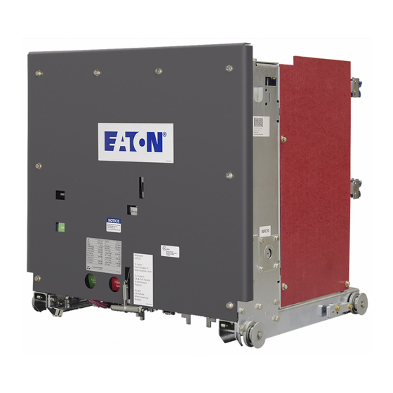
- Page 80 Kit Part Number = 68C5010G41 Roll on Floor Wheel Kit shown installed on a standard 5/15kV VCP-W Breaker. 7.4 “Optional” Factory Installed Roll On Floor Wheel Kit E f f ec t iv e 0 7/ 2 0 1 7...
- Page 81 WARRANTIES ARISING FROM COURSE OF DEALING OR USAGE OF TRADE, ARE MADE REGARDING THE INFORMATION, RECOMMENDATIONS DESCRIPTIONS CONTAINED HEREIN. In no event will Eaton be responsible to the purchaser or user in contract, in tort (including negligence), strict liability or otherwise special, indirect,...
Need help?
Do you have a question about the VCP-W and is the answer not in the manual?
Questions and answers