
Related Manuals for Fermax MILO


Summary of Contents for Fermax MILO
- Page 1 MILO DIGITAL VIDEO PANEL INSTALLER'S MANUAL ENGLISH Version Cod. 970134Ic V08_19 This manual corresponds to MEET Digital Video Panel firmware version V02.09 and hardware HW 95770B / HW 95771B.
- Page 2 FERMAX ELECTRÓNICA S.A.U. http://www.fermax.com MILO DIGITAL VIDEO Panel manual available at https://meet.fermax.com/milo-panel/ Copyright Notice Fermax and Fermax MILO panel are trademarks of Fermax Electronica S.A.U. registered in the European Union and other countries. © FERMAX ELECTRÓNICA S.A.U., 2019. Page 2...
-
Page 3: Table Of Contents
INDEX Product Introduction ....................... 4 Overview ........................ 4 Panel Display Screen .................... 5 Functions Introduction ....................5 Call Apartment ....................... 6 Block Panel call apartment ................ 6 2.1.1 General Entry Panel call apartment ............6 2.1.2 Call Guard Unit ...................... 7 Block Panel Call Guard Unit .............. -
Page 4: Product Introduction
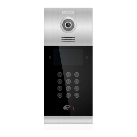
1 Product Introduction Overview High definition camera 1,2Mpx Lighting for night vision with LEDs Speaker Motion sensor 4.3” TFT Digital keyboard (capacitive or mechanical) Key “B” Mifare reader Microphone Slider Page 4... -
Page 5: Panel Display Screen
Panel Display Screen Network Status 2 Functions Introduction Call apartment Call concierge Call volume settings Door opening, relay delay settings Connect exit button Speech Door opened, door forced alarm, and tamper alarm Lift control (Only when installed) PIN Access Code ... -
Page 6: Call Apartment
Call Apartment 2.1.1 Block Panel call apartment Visitors need to enter apartment number followed by “B” to confirm. For example, if the resident lives in apartment 201, the visitor should enter: 201 and press “B”. 2.1.2 General Entry Panel call apartment Visitors need to enter block number followed by a 4 digits apartment number followed by “B”... -
Page 7: Call Guard Unit
Call Guard Unit 2.2.1 Block Panel Call Guard Unit The visitor or resident can call the guard unit by entering the number assigned to it (9901 by default) followed by “B” to confirm. This call can be made from all block entry panels. 2.2.1 General Entry Panel Call Guard Unit The visitor or resident can call the guard unit by entering the number assigned to it (9901 by default) followed by “B”... -
Page 8: Access Code
Access Code Press keys “A0” to access PIN code function, entering the access code followed by “B” to confirm. If the access code is correct the door will open. You can enable or disable the function at web of the panel. The access code to be defined at web of the panel. -
Page 9: About
About Enter code 9999 followed by “B” to confirm, The ABOUT information will show. You can get information about the device name, firmware version, device info, serial no, IP address and MAC address. Page 9... -
Page 10: Configuration Via Web Server
3 Configuration via Web Server The panel has an integrated web server, which allows to configure the parameters. This web server is accessed via the panel’s IP address. Use preferably Chrome web browser. As a first step, username and password is reqested. DEFAULT VALUES: IP: 10.1.0.1 Username: admin... -
Page 11: General Settings
General Settings Configures the panel type: General entrance panel or block panel. 3.2.1 General Entrance Panel DEVICE NO.: General entrance panel number, between 1 and 9000. TYPE: G.E.PANEL. The panel can communicate with all devices (monitors or concierges) of the installation. LANGUAGE: select the desired language in the dropdown options. -
Page 12: Block Panel
3.2.2 Block Panel DEVICE NO. Block number, between 1 and 999 (default 1). TYPE: Select BLOCK PANEL. Between 01-99 (default 1). LANGUAGE: select the desired language in the dropdown options. (Default option ENGLISH). Refresh the webpage after change the language. INFORMATION: 9901 CONCIERGE, Prompt information to be displayed on the panel, between 9901-9998, (default option 9901). - Page 13 is to be used the most usually. SIP DIVERT MODE: PARALLEL CALL: When the panel calls the resident, the monitor and the call divert APP ring at the same time. Once one terminal answers the call the other one stops ringing. SEQUENTIAL CALL: When the panel calls the resident, the monitor will ring about 30s if no answer, the call divert APP will start to ring This feature may not be available in this version.
-
Page 14: Network Settings
Network Settings MEET allows the installer to define the IP range according to the project needs and make the network management easier. MEET IP assignations network mode is static mode. This ensure that each device has a unique IP address in same installation. The devices (digital panel, monitor and guard unit) will show IP conflict if there same IP is used on the same LAN. -
Page 15: Access
Access DOOR RELAY TIME: Time for lock-release relay remains active (option 1-9 s). DOOR DELAY TIME: Is the time lasted between the moment in that the open door order has been sent and the moment in that the realy is activated. Open door relay is useful when the door is quite far from the panel. -
Page 16: Face Recognition
Face Recognition FACE RECOGNITION: Enable or disabled face recognition function. SIMILARITY: High, medium and low options. Default is LOW. The face data must be added through MEET management software. Page 16... -
Page 17: Ip Camera
IP Camera The monitor can switch to IP CCTV camera video during a conversation. This function allows to configure IP CCTV cameras using RTSP protocol to be displayed as an auxiliary camera to provide different view angles from the door or related areas. NUMBER OF CAMS: IP camera Number. - Page 18 REMARK: When the panel is used as a SIP device, SIP function has to be enabled and all SIP parameters corresponding to the used SIP server shall be configured. Page 18...
-
Page 19: Sip Trunk
SIP Trunk VoIP When there is a gateway installed on the system or a sip server has a PSTN line. The panel call can be diverted to user's mobile phone or land line telephone through a voice gateway. SIP trunk ENABLE SIP TRUNK: Enable or disable function. -
Page 20: Pincode Settings
Pincode Settings This allows to change the pin code of the web server login. Restore RESTORE FACTORY SETTINGS: All the settings are restored to the factory settings. The IP address will be changed to the default IP: 10.1.0.1 REBOOT DEVICE: The panel will be restarted and will keep all the previous settings. Page 20... -
Page 21: Logout
Logout Log out the web server. Page 21... -
Page 22: Installation
4 Installation Installation height Page 22... -
Page 23: Installation Step Diagram
Installation Step Diagram 1. Flush box install. 3. The upper part of the panel is 2. Base flush box depth adjustment hook. stuck in, then move the panel to the flush box. 2.2CM 2.2CM 4. Move the slider of the panel and fix the two screws. When installing, pay attention to the reservation of the 2.2 cm space around the door to move the slide cover. -
Page 24: Connectors
Connectors 10/100Mbps RJ45 Port. +, —: 12Vdc Power Input. Relay contacts for release lock, the double terminals are the same connection. C, NO, NC: +5V, —, WD0, WD1: Wigand-26 protocol output or input. EXIT, —: Exit button. ... -
Page 25: Technical Parameters
IC cards: 100,000 Face data: 6000 Operating temperature: -10~70℃ Relative humidity: 20%~80%, without condensation RADIO FREQUENCY MODULE. EC DECLARATION OF CONFORMITY: FERMAX ELECTRÓNICA, S.A.U. declares that this product complies with the requirements in the RED 2014/53/EU Directive “Radio frequency equipment”. https://www.fermax.com/intl/en/pro/documents/technical-documentation/DT- 13-declarations-of-conformity.html Radio frequency module: Frequency: 13.56MHz / Maximum Power:...
Need help?
Do you have a question about the MILO and is the answer not in the manual?
Questions and answers