Table of Contents
Advertisement
Quick Links
Advertisement
Table of Contents

Related Manuals for 4RF Aprisa SRi


Summary of Contents for 4RF Aprisa SRi
- Page 1 August 2019 Version 1.1.0a...
- Page 3 Copyright © 2019 4RF Limited. All rights reserved. This document is protected by copyright belonging to 4RF Limited and may not be reproduced or republished in whole or part in any form without the prior written permission of 4RF Limited.
- Page 4 / or license conditions. The term ‘Radio’ with reference to the Aprisa SRi User Manual, is a generic term for one end station of a point-to-multipoint Aprisa SRi network and does not confer any rights to connect to any public network or to operate the equipment within any territory.
- Page 5 Compliance United States of America FCC The Aprisa SRi radio is designed to comply with the USA Federal Communications Commission (FCC) specifications as follows: Radio 47CFR Part 15.247 47CFR Part 15 Subpart C Radio Frequency Devices Environmental EN 300 019, Class 3.4...
- Page 6 Compliance Canada ISED The Aprisa SRi radio is designed to comply with Innovation, Science and Economic Development (ISED) specifications as follows: Radio RSS-247 This Class A digital apparatus complies with Canadian standard RSS-Gen. Environmental EN 300 019, Class 3.4 Ingress Protection IP51...
- Page 7 915-928 MHz 50 kHz 10-30 VDC Complete Compliance New Zealand RSM The Aprisa SRi radio is designed to comply with New Zealand RSM specifications as follows: Radio / EMC AS/NZS 4268 Environmental EN 300 019, Class 3.4 Ingress Protection IP51...
- Page 8 Compliance Mexico IFETEL The Aprisa SRi radio is designed to comply with the Mexico IFETEL specifications as follows: Radio / EMC NOM-208-SCFI-2016 Environmental EN 300 019, Class 3.4 Ingress Protection IP51 Safety EN 60950-1:2006 Class 1 division 2 for hazardous locations...
- Page 9 WARNING: EXPLOSION HAZARD - Do not connect or disconnect while circuits are live unless area is known to be non-hazardous. The following text is printed on the Aprisa SRi where the end user is in Canada: AVERTISSEMENT: RISQUE D'EXPLOSION - Ne pas brancher ou débrancher tant que le circuit est sous tension,...
-
Page 11: Table Of Contents
Contact Us ................. 19 What’s in the Box ................20 Aprisa SRi Accessory Kit ..............20 About the Radio ................. 21 The 4RF Aprisa SRi Radio ............... 21 Product Features ................22 Functions .................. 22 Security ..................23 Performance ................24 Usability ................... - Page 12 Required Tools ................72 DIN Rail Mounting ................ 73 Rack Shelf Mounting ..............74 Wall Mounting ................75 Installing the Antenna and Feeder Cable ............ 76 Connecting the Power Supply ..............77 External Power Supplies ..............77 Aprisa SRi User Manual 1.1.0...
- Page 13 USB Serial Ports ................318 USB RS-232 / RS-485 Serial Port ............318 USB RS-232 / RS-485 operation ............318 USB RS-232 Cabling Options ............319 USB RS-485 Cabling Options ............319 USB Retention Clip .............. 320 Aprisa SRi User Manual 1.1.0...
- Page 14 RS-232 Asynchronous Interface ............345 Hardware Alarms Interface ............346 Power Specifications ................347 Power Supply ................347 Power Consumption ..............347 Power Dissipation ..............347 General Specifications ................ 348 Environmental ................348 Mechanical ................348 Compliance ................349 Aprisa SRi User Manual 1.1.0...
- Page 15 The WEEE Symbol Explained ............350 WEEE Must Be Collected Separately ..........350 YOUR ROLE in the Recovery of WEEE ..........350 EEE Waste Impacts the Environment and Health ........350 15. Copyrights ................351 16. Abbreviations ................353 Aprisa SRi User Manual 1.1.0...
-
Page 17: Getting Started
Getting Started | 17 Getting Started This section is an overview of the steps required to commission an Aprisa SRi radio network in the field: Phase 1: Pre-installation Confirm path planning. Page 66 Ensure that the site preparation is complete: Page 69 •... - Page 18 Compare the actual RSSI to the expected RSSI value (from your path planning). Page 283 Align the antennas. Page 315 Confirm that the radio is operating correctly; the OK, MODE and AUX LEDs are green. Aprisa SRi User Manual 1.1.0...
-
Page 19: Introduction
This manual has been written for professional field technicians and engineers who have an appropriate level of training and experience. Contact Us If you experience any difficulty installing or using the Aprisa SRi radio after reading this manual, please contact Customer Support or your local 4RF representative. The 4RF New Zealand head office is:... -
Page 20: What's In The Box
20 | Introduction What’s in the Box Inside the box you will find: • One Aprisa SRi radio fitted with a power connector. • One Aprisa SRi Accessory kit containing the following: Aprisa SRi Quick Start Guide Management Cable Aprisa SRi Accessory Kit... -
Page 21: About The Radio
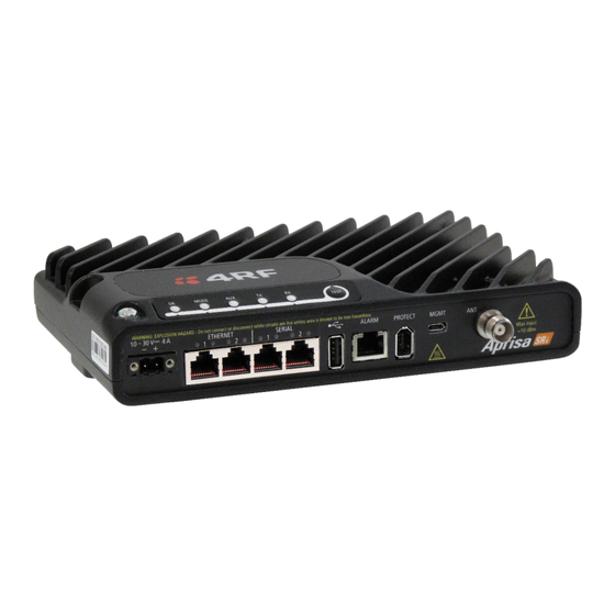
About the Radio The 4RF Aprisa SRi Radio The 4RF Aprisa SRi is a Point-To-Multipoint (PMP) digital radio providing 915 MHz Industrial Licence Free Spread Spectrum communications. The radios carry a combination of serial data and Ethernet data between the base station and remote radios. -
Page 22: Product Features
SuperVisor Extended Network Management (EXM) extending SuperVisor management beyond the single radio network providing configuration and monitoring to other Aprisa SR family products • SNMPv1/2/3 & encryption MIB supports for 4RF SNMP manager or third party SNMP agent network management •... -
Page 23: Security
About the Radio | 23 Security The Aprisa SRi provides security features to implement the key recommendations for industrial control systems. The security provided builds upon the best in class from multiple standards bodies, including: • IEC/TR 62443 (TC65) ‘Industrial Communications Networks – Network and System Security’... -
Page 24: Performance
Dedicated alarm port • Software upgrade and diagnostic reporting via the host port USB flash drive • Over-the-air software distribution and upgrades • Simple installation with integrated mounting holes for wall, DIN rail and rack shelf mounting Aprisa SRi User Manual 1.1.0... -
Page 25: Product Overview
Network Coverage and Capacity The Aprisa SRi has a typical link range of up to 50 km / 30 miles, however, geographic features, such as hills, mountains, trees and foliage, or other path obstructions, such as buildings, will limit radio coverage. -
Page 26: Architecture
Remote nodes are predominantly in receive mode with only sporadic bursts of transmit data. This reduces power consumption. The Aprisa SRi is a packet based radio. Data is sent over the wireless channel in discrete packets / frames, separated in time. The PHY demodulates data within these packets with coherent detection. -
Page 27: Data Link Layer / Mac Layer
Data Link Layer / MAC layer The Aprisa SRi PHY enables multiple users to be able to share a single wireless channel; however a DLL is required to manage data transport. The two key components to the DLL are channel access and hop by hop transmission. -
Page 28: Adaptive Coding And Modulation
28 | About the Radio Adaptive Coding and Modulation The Aprisa SRi provides Adaptive Coding and Modulation (ACM) which maximizes the use of the RF path to provide the highest radio capacity available. ACM automatically adjusts the modulation coding and FEC code rate in the remote to base direction of transmission over the defined modulation range based on the signal quality for each individual remote radio. -
Page 29: Zones And Channels
918.0938 923.0313 921.4688 Zone 6 918.1563 923.0938 921.525 921.2188 924.5938 923.4375 Zone 7 921.2813 924.6563 923.4938 924.3438 926.1563 925.4063 Zone 8 924.4063 926.2188 925.4625 927.4688 927.7188 0.25 927.375 0.596875 Total Zone BW 3.125 1.5625 1.9125 Aprisa SRi User Manual 1.1.0... -
Page 30: Frequency Hopping Synchronization
A remote will override its configured channels once it registers and gets updates from base station or when base station changes its channels configuration. At power-on, the Aprisa SRi base station immediately starts hopping and sending packets, ACKs and beacon control packets. When a remote is powered-on or has lost sync with the base station, it picks a random channel from its hop channel set and listens for a beacon with a default of up to 180 seconds (a good link sync on average will be <... -
Page 31: Interference Avoidance / Immunity
ARQ mechanism. ARQ (Automatic Repeat reQuest) is a well-known data integrity mechanism used in the Aprisa SRi as it adds a layer of interference recovery on top of the powerful Aprisa FEC (Forward Error Correction). Some frequencies may be subject to more interference than others so if packet retries are enabled in the Aprisa SRi and interference on a specific frequency overwhelms the FEC, then any missing packets are automatically retransmitted on another frequency. -
Page 32: Two Base Stations Using The Same Antenna
32 | About the Radio Two Base Stations Using the Same Antenna Two Aprisa SRi base stations can be used with the same antenna (overlapping coverage). This can be done with the G5 tuned duplexer (see ‘Duplexer Kits’ on page 317). -
Page 33: Network Layer
Aprisa SRi router mode (see figure below), enables the routing of IP packets within the Aprisa SRi wireless network and in and out to the external router / IP RTUs devices connected to the Aprisa SRi wired Ethernet ports. -
Page 34: Static Ip Router
Ethernet Interface and for routers which are connected to the radio network. The Aprisa SRi base station is used as a gateway to other networks. Thus, a configurable IP address default gateway can be set using a static route in the routing table with a destination IP address of the destination network address. - Page 35 Ethernet interface’ on each radio in the network is the ‘router port’. The routing table for all directly attached devices to the Aprisa SRi network, at the Base or the Remote radios is automatically built, and no static routes are required to be entered for those device routes.
- Page 36 Gateway Router Mode (AGRM) and the remote radios are in bridge mode (where the base station is AGRM / ARM and all remotes must be in the same bridge mode). RTUs must set their default gateway to 10.10.1.1 which is RF IP Address of base station to reach the SCADA master. Aprisa SRi User Manual 1.1.0...
- Page 37 Router Mode (ARM) and remote radios are in bridge mode. It’s the same case as the AGRM-Bridge network above, but each Ethernet interface has a different IP address and subnet at the ARM base station. Aprisa SRi User Manual 1.1.0...
- Page 38 Bridge-Mix [AGRM / ARM and Bridge] network can be created. A network configuration warning alarm will be raised on base station if this condition is not met. • The ARP table will report a radio interface IP address if any address is learned on this interface. Aprisa SRi User Manual 1.1.0...
- Page 39 Auto route build for the associated devices to the radio network (i.e. next hop devices) is only supported in the standard router modes where the base station, and remote radios are all in standard router modes. Aprisa SRi User Manual 1.1.0...
- Page 40 Static IP Router – Human Error Free To ensure correct operation, the Aprisa SRi router base station alerts when one (or more) of the devices is not configured for router mode or a duplicated IP is detected when manually added.
- Page 41 Session originating from internal / local to external network domain will be considered as outbound traffic. Outbound session only may for example represent report by exception. Inbound and Outbound session may for example represent poll / response. Aprisa SRi User Manual 1.1.0...
- Page 42 ‘IP > NAT > Settings TAB’ in ‘Session Idle Timeout’. NAT packet statistics of inbound and outbound sessions are also reported in the NAT session table per session basis. Aprisa SRi User Manual 1.1.0...
- Page 43 For smooth protection switching and continuous traffic flow, the protected station automatically supports MAC address cloning for both active and standby radios NAT public interface (the cloned MAC address is presented in ‘RF Mac Address’ field (see ‘Maintenance > Advanced’ on page 243). Aprisa SRi User Manual 1.1.0...
- Page 44 IP address range 192.168.2.4 - 5 to private IP address range 10.10.1.2 – 3. NAT Address Map Table of remote- 2 shows reuse of the same private IP address range where NAT will translate public IP address range 192.168.2.7 - 8 to private IP address range 10.10.1.2 – 3. Aprisa SRi User Manual 1.1.0...
- Page 45 Outbound session #3 shows the response of RTU-1 to SCADA master and NAT translation of Eth port private source address 10.10.1.2 to 192.168.2.4 on RF port public source address. The destination address of SCADA master 172.16.1.1 remains unchanged during the outbound NAT translation. Aprisa SRi User Manual 1.1.0...
- Page 46 NAT translation and routing. After a protection switch-over, the NAT session table will be aged. For smooth protection switching and continuous traffic flow, the public interface MAC address will be used. Aprisa SRi User Manual 1.1.0...
- Page 47 192.168.2.2 172.16.1.1 10.10.1.3 172.16.1.1 RTU-1 (Telnet) > SCADA 172.16.1.1 192.168.2.2 172.16.1.1 10.10.1.3 To Base CPU (and drop) 172.16.1.1 192.168.2.2 ICMP 172.16.1.1 10.10.1.1 Ping (Req.) > Remote-2 192.168.2.2 172.16.1.1 ICMP 10.10.1.1 172.16.1.1 Remote-2 > Ping (Resp.) Aprisa SRi User Manual 1.1.0...
- Page 48 To run a ping across port forwarding NAT, user can use the hrPing.exe utility (run as admin) that can control the ping query ID value. Standard Windows ping command doesn’t have the capability to control the ping query ID value. Aprisa SRi User Manual 1.1.0...
-
Page 49: Bridge Mode With Vlan Aware
Ethernet VLAN Bridge / Switch Overview The Aprisa SRi in Bridge mode of operation is a standard Ethernet Bridge based on IEEE 802.1d or VLAN Bridge based on IEEE 802.1q/p which forward / switch Ethernet packet based on standard MAC addresses and VLANs using FDB (forwarding database) table decisions. -
Page 50: Vlan Bridge Mode Description
/ radio as interfaces and serial ports using terminal server as a virtual interface. The Aprisa SRi is a standard IEEE 802.1q VLAN bridge, where the FDB table is created by the bridge learning / aging process. New MACs are learnt and the FDB table updated. Unused MACs are aged out and flushed automatically after aging period. - Page 51 VLANs carry 3 priority bits (PCP field) in the VLAN tag allowing prioritization of VLAN tagged traffic types with 8 levels of priority (where 7 is the highest priority and 0 is the lowest priority). The Aprisa SRi supports QoS (Quality of Service) where the priority bits in the VLAN tagged frame are evaluated and mapped to four priority levels and four queues supported by the Aprisa SRi radio.
-
Page 52: Avoiding Narrow Band Radio Traffic Overloading
SCADA traffic transmission relative to any other unimportant traffic. In this case, traffic based on VLAN priority (priority 0 to 7) enters one of the four priority queues of the Aprisa SRi (Very High, High, Medium and Low). Traffic leaves the queues (to the radio network) from highest priority to lowest in a strict priority fashion. - Page 53 Payload Compression Aprisa SRi supports payload compression. A Lempel–Ziv (LZ) algorithm is used to efficiently compress up to 50% traffic with high percentage of repetitive strings. Both serial and Ethernet / IP payload traffic are compressed.
-
Page 54: Interfaces
Used for software upgrade, diagnostic reporting and configuration save / restore. Protect Interface • 1x Protect interface port Not applicable for the Aprisa SRi radio. Alarms Interface • 1x Alarm port using RJ45 connector Used to provide 2 x hardware alarm inputs and 2 x hardware alarm outputs... -
Page 55: Front Panel Connections
See ‘Connecting to the CLI via the Management Port’ on page 306 PROTECT Protect port. Not used for the SRi. TNC, 50 ohm, female connector for connection of antenna feeder cable for half duplex RF operation. See ‘Coaxial Feeder Cables’ on page 69. Aprisa SRi User Manual 1.1.0... -
Page 56: Led Display Panel
56 | About the Radio LED Display Panel The Aprisa SRi has an LED Display panel which provides on-site alarms / diagnostics without the need for The LEDs indicate the following conditions: MODE Flashing Radio has not registered Alarm present... -
Page 57: Single Radio Software Upgrade
Software upgrade completed successfully - the OK LED flashes green • Software upgrade failed - any LED flashing red during the upgrade Network Software Upgrade During a network software upgrade, the MODE LED flashes orange on the base station and all remote radios. Aprisa SRi User Manual 1.1.0... -
Page 58: Test Mode
Note: Test Mode traffic has a low priority but could affect customer traffic depending on the relative priorities setup. The RSSI result is displayed on the LED Display panel as a combination of LED states: Aprisa SRi User Manual 1.1.0... -
Page 59: Network Management
The Aprisa SRi contains an embedded web server application (SuperVisor) to enable element management with any major web browser (such as Mozilla Firefox or Microsoft® Internet Explorer). SuperVisor enables operators to configure and manage the Aprisa SRi base station radio and remote radios over the radio link. -
Page 60: Hardware Alarm Inputs / Outputs
SuperVisor event history log (see ‘Events > Event History’ on page 246). These include the alarm events generated by the hardware alarm inputs. Alarm Input to SNMP Trap An alarm event from an Aprisa SRi hardware alarm input can be sent over the air to any SNMP Manager using SNMP traps. Aprisa SRi User Manual 1.1.0... -
Page 61: Implementing The Network
5. Set the radio zones / channels to be compatible with the base station. 6. Set the radio security settings to the same as the base station (see ‘Security > Setup’ on page 202). The base station will automatically allocate a node address to the new remote radio. Aprisa SRi User Manual 1.1.0... -
Page 62: Network Changes
To remove a remote radio from your network: 1. Turn the power off on the remote radio you wish to remove. This is the only action that is required. Note: The remote radio will continue to show in the Network Table list. Aprisa SRi User Manual 1.1.0... -
Page 63: Preparation
Use double-screened coaxial cable that is suitable for use up to 1 GHz at ≈ 1 metre. CAUTION: Do not apply signals greater than +10 dBm to the antenna connection as they can damage the receiver. Aprisa SRi User Manual 1.1.0... -
Page 64: Compliance Considerations
Compliance Considerations The Aprisa SRi is a professional radio product and as such must be installed by a suitably trained and qualified installer who is aware of the local regulatory requirements existing at the time of installation and is capable of ensuring that the regulations are adhered to. -
Page 65: Canada
Preparation | 65 The Aprisa SRi has a maximum mean output power of +26 dBm into a 50 ohm antenna which equates to a maximum peak power of +30 dBm PEP. To determine the maximum power to be set on the Aprisa SRi, the... -
Page 66: Path Planning
The predominant antenna for a base station is an omni-directional collinear gain antenna. Omni Directional Collinear Antennas Factor Explanation Gain Varies with size (5 dBi to 11 dBi typical) Wind loading Minimal Tower aperture required Minimal Size Range from 2 m to 3 m length Polarization Vertical Aprisa SRi User Manual 1.1.0... -
Page 67: Remote Radio
Low (typically 18 to 20 dB) It is possible to increase the gain of a Yagi antenna installation by placing two or more of them in a stack. The relative position of the antennas is critical. Example of stacked antennas Aprisa SRi User Manual 1.1.0... -
Page 68: Antenna Siting
The antenna site should be as close as possible to the equipment shelter. Wide angle and zoom photographs taken at the proposed antenna location (looking down the proposed path), can be useful when considering the best mounting positions. Aprisa SRi User Manual 1.1.0... -
Page 69: Coaxial Feeder Cables
System Plan predicts how well the radios will perform after it is installed. Use the outputs of the Linking System Plan during commissioning to confirm the radios have been installed correctly and that it will provide reliable service. Aprisa SRi User Manual 1.1.0... -
Page 70: Site Requirements
DC power connection. Equipment Cooling If the Aprisa SRi is operated in an environment where the ambient temperature exceeds 50°C, the Aprisa SRi convection air flow over the heat sinks must be considered. The environmental operating conditions are as follows: Operating temperature -40 to +70˚... -
Page 71: Earthing And Lightning Protection
Radio Earthing The Aprisa SRi has an earth connection point on the top left of the enclosure. M4 8mm pan pozi machine screws and M4 lock washers are supplied fitted to the radio. These screws can be used to earth the enclosure to a protection earth. -
Page 72: Installing The Radio
4RF does not assume any liability for failure to comply with these precautions. Mounting The Aprisa SRi has four threaded holes (M4) in the enclosure base and two holes (5.2 mm) through the enclosure for mounting. Mounting options include: •... -
Page 73: Din Rail Mounting
4RF SR+ Acc, Mounting, Bracket, DIN Rail The Aprisa SRi is mounted into the DIN rail mounting bracket using the four M4 threaded holes in the Aprisa SRi enclosure base. Four 8 mm M4 pan pozi machine screws are supplied with the bracket. -
Page 74: Rack Shelf Mounting
Rack Shelf Mounting The Aprisa SRi can be mounted on a rack mount shelf using the four M4 threaded holes in the Aprisa SRi enclosure base. The following picture shows Aprisa SRi mounted on a 1 RU rack mounted shelf. -
Page 75: Wall Mounting
Installing the Radio | 75 Wall Mounting The Aprisa SRi can be mounted on a wall using the two holes through the enclosure (5.2 mm diameter). Typically, M5 screws longer than 35 mm would be used. Aprisa SRi User Manual 1.1.0... -
Page 76: Installing The Antenna And Feeder Cable
Connect the antenna and feeder cable. Weatherproof the connection with a boot, tape or other approved method. The Aprisa SRi antenna connection is a TNC female connector so the feeder / jumper must be fitted with a TNC male connector. -
Page 77: Connecting The Power Supply
The power connector required is a Molex 2 pin female screw fitting part. This connector is supplied fitted to the radio. The negative supply of the Aprisa SRi power connection is internally connected to the Aprisa SRi enclosure. Power must be supplied from a Negative Earthed power supply. -
Page 79: Managing The Radio
The Aprisa SRi contains an embedded web server application (SuperVisor) to enable element management with any major web browser (such as Mozilla Firefox or Microsoft® Internet Explorer). SuperVisor enables operators to configure and manage the Aprisa SRi base station radio and remote radios over the radio link. -
Page 80: Pc Requirements For Supervisor
Pentium 4 and above (4RF does not support retina displays) Note 1: 4RF does not support Windows 10 Edge, Google Chrome, Opera or Apple Safari browsers but when they have been used, they have worked correctly. Aprisa SRi User Manual 1.1.0... -
Page 81: Connecting To Supervisor
IP networking. There should be only one Ethernet connection from the base station to the management network. The Aprisa SRi has a factory default IP address of 169.254.50.10 with a subnet mask of 255.255.0.0. This is an IPv4 Link Local (RFC3927) address which simplifies the connection to a PC. -
Page 82: Management Pc Connection
This includes the ability to monitor the ‘Last received packet RSSI. If ICMP is enabled on the base station, the user will also be able to ping the base station to confirm the connectivity. Aprisa SRi User Manual 1.1.0... -
Page 83: Pc Settings For Supervisor
If the radio is on a different subnet from the network the PC is on, set the PC default gateway address to the network gateway address which is the address of the router used to connect the subnets (for details, consult your network administrator). Aprisa SRi User Manual 1.1.0... - Page 84 Connection setting to ‘Never dial a connection’. Windows Internet Explorer 8 example: 1. Open Internet Explorer. 2. Open the menu item Tools > Internet Options and click on the ‘Connections’ tab. 3. Click the ‘Never dial a connection’ option. Aprisa SRi User Manual 1.1.0...
- Page 85 3. Click on ‘Pop-up Blocker Settings’. 4. Set the ‘Address of Web site to allow’ to the radio address or set the ‘Blocking Level’ to ‘Low: Allow Pop-ups from secure sites’ and close the window. Aprisa SRi User Manual 1.1.0...
- Page 86 2. Open the menu item Tools > Internet Options and click on the ‘Security’ tab. 3. Click on ‘Local Intranet’. 4. Click on ‘Custom Level’. 5. Scroll down until you see section labeled ‘Scripting’. 6. Under ‘Active Scripting’, select ‘Enable’. Aprisa SRi User Manual 1.1.0...
-
Page 87: Login To Supervisor
‘Command Line Interface’ on page 306). Note: The Aprisa SRi has a randomly generated unique self-signed ECC256 security certificate which may cause the browser to prompt a certificate warning. It is safe to ignore the warning and continue. The valid certificate is ‘Issued By: 4RF-APRISA’... - Page 88 (Level 1 or Level 2 lockout), SuperVisor will display an ‘Account Locked’ message. Login If a login attempt failed due to permanent lockout of the account (continued failed login attempts even after levels 1 and 2 lockout periods), SuperVisor will display an ‘Account Locked’ message. Aprisa SRi User Manual 1.1.0...
- Page 89 If the submitted password for the account recovery process was invalid, SuperVisor will display a message indicating that the recovery process has failed. Aprisa SRi User Manual 1.1.0...
-
Page 90: Logout Of Supervisor
If the SuperVisor window is closed without logging out, the radio will automatically log the user out after a timeout period of 3 minutes. To logout of SuperVisor: Click on the ‘Logout’ button on the Summary Bar. Aprisa SRi User Manual 1.1.0... -
Page 91: Supervisor Page Layout
The following shows the components of the SuperVisor page layout for a standard radio: SuperVisor Branding Bar The branding bar at the top of the SuperVisor frame shows the branding of SuperVisor on the left and the product branding on the right. Aprisa SRi User Manual 1.1.0... - Page 92 Ready - SuperVisor is ready to manage the radio. Middle Displays the name of the radio terminal that SuperVisor is currently managing. Right The access level logged into SuperVisor. This label also doubles as the SuperVisor logout button. Aprisa SRi User Manual 1.1.0...
-
Page 93: Supervisor Extended Network Management (Exm)
A typical use of this new feature is where an Aprisa SRi radio network is connected to the ‘tail end’ of an Aprisa SR+ radio network where the Aprisa SRi base station is cable connected to the Ethernet port of an Aprisa SR+ remote radio. - Page 94 Clicking any top level menu after the connection is established will open the page for the radio connected to The Network Table shows the radio connected to. To see the complete Network Table of the radio connected to, click the Network Table button. Aprisa SRi User Manual 1.1.0...
-
Page 95: Supervisor Menu
Events Software Monitoring SuperVisor Parameter Settings Changes to parameters settings have no effect until the ‘Save’ button is clicked. Click the ‘Save’ button to apply the changes or ‘Cancel’ button to restore the current value. Aprisa SRi User Manual 1.1.0... -
Page 96: Supervisor Menu Access
Security > SNMP No Access No Access No Access Read-Write Security > Manager No Access No Access Read-Write Read-Write Security > Distribution No Access No Access Read-Write Read-Write Maintenance > Summary Read-Only Read-Only Read-Only Read-Only Aprisa SRi User Manual 1.1.0... - Page 97 Read-Only Read-Only Read-Only Read-Only Network Settings Menu Items Menu Item View Technician Engineer Admin Network Table Read-Only Read-Only Read-Only Read-Only Summary Read-Only Read-Only Read-Only Read-Only Exceptions Read-Only Read-Only Read-Only Read-Only View Read-Only Read-Only Read-Only Read-Only Aprisa SRi User Manual 1.1.0...
-
Page 98: Supervisor
Ethernet availability on the radio see ‘Maintenance > Licence’ on page 237. TX Power (dBm) This parameter displays the current Transmit Power in dBm. Channel Size (kHz) This parameter displays the current Channel Size in kHz. Aprisa SRi User Manual 1.1.0... - Page 99 000B to 01FE. Network Radius This parameter indicates a Network Repeaters Proximity setting of ‘No Repeater’ or ‘Base-Repeater’. Not applicable for the Aprisa SRi. Inband Management This parameter displays the status of the Inband Management option. Inband Management Timeout (sec) This parameter displays the number of seconds that the base station waits for a response from a remote radio before aborting the Inband Management request.
- Page 100 Radio Serial Number This parameter displays the Serial Number of the radio (shown on the enclosure label). Sub-Assembly Serial Number This parameter displays the Serial Number of the printed circuit board assembly (shown on the PCB label). Aprisa SRi User Manual 1.1.0...
- Page 101 Previous Software Version This parameter displays the software version that was running on the radio prior to the current software being activated. A new radio from the factory will display ‘None’ for the Previous SW Version. Aprisa SRi User Manual 1.1.0...
- Page 102 1. Enter the Terminal Name. 2. Enter the Location of the radio. 3. Enter a Contact Name. The default value is ‘4RF Limited’. 4. Enter the Contact Details. The default value is ‘support@4RF.com’. GPS Coordinates This parameter sets the GPS Coordinates for the radio location.
- Page 103 Managing the Radio | 103 GPS Status This field displays the status of the GPS Receiver if enabled (see ‘ Aprisa SRi User Manual 1.1.0...
- Page 104 The Update GPS button updates the GPS Coordinates field from the installed USB GPS Receiver. If the GPS Receiver is enabled but is not operating or not receiving a valid GPS signal, the GPS Status will show ‘Update Failed’. Aprisa SRi User Manual 1.1.0...
- Page 105 It is especially important to set different values for each network when two or more networks using the same frequencies are operating with some overlapping coverage. The entry is an integer from 1 to 8. Aprisa SRi User Manual 1.1.0...
- Page 106 Inband Management Timeout (sec) This parameter sets the Inband Management timeout period. This determines the time the base station waits for a response from a remote before aborting the Inband Management request. The default setting is 10 seconds. Aprisa SRi User Manual 1.1.0...
- Page 107 It can be configured on a remote radio if required but not on all remotes as SNTP requests could overload the network. For high availability time/date synchronization, SNTP can be synchronized from two SNTP servers for server backup. Aprisa SRi User Manual 1.1.0...
- Page 108 The Time Zone Offset is the number of hours / minutes offset from UTC time. The default setting is ‘No Offset’. Clicking the Time Zone Offset field brings up a pop-up to enter the offset. After selecting the offset, review the current date and time before saving the changes. Aprisa SRi User Manual 1.1.0...
- Page 109 SNTP server on Time Server 1 Address, synchronization will be attempted to the SNTP server on this address. Synchronization Status This field shows the status of the current synchronization or the result of the last synchronization. Synchronize Now This Synchronize Now button provides manual Synchronization. Aprisa SRi User Manual 1.1.0...
- Page 110 The base-repeater has the same function as the base station but used when peer to peer connections between remotes is required via the base station. Not applicable for the Aprisa SRi radio. Remote The remote in most cases is used as the end-point of the SCADA network connected to an RTU or PLC device for SCADA network control and monitoring.
- Page 111 The radio operates normally. Disabled Disables all RF over-the-air communications from the RF port and turns off the transmitter and receiver to save power. This enables a radio to be used as a Terminal Server without RF. Aprisa SRi User Manual 1.1.0...
-
Page 112: Radio
112 | Managing the Radio Radio Radio > Radio Summary This page displays the current settings for the Radio parameters. See ‘Radio > Radio Setup’ and ‘Radio > Channel Setup’ for setting details. Aprisa SRi User Manual 1.1.0... - Page 113 Payload Compression Ratio The payload is compressed using level 3 QuickLZ data compression. Payload Compression is automatic and cannot be turned off by SuperVisor. Compression is not attempted on data that is already compressed e.g. jpg files. Aprisa SRi User Manual 1.1.0...
- Page 114 The zone number defined in the regulatory specification. The maximum number of standard hop zones is 8. Enabled Displays the hop zones enabled. Frequencies Displays the zone frequencies defined for the zone hop number. Channels Enabled Displays the number of channels selected in the zone. Aprisa SRi User Manual 1.1.0...
- Page 115 Managing the Radio | 115 The Zone Summary > Zones shows the channels enabled per zone hop 1 to 8. Aprisa SRi User Manual 1.1.0...
- Page 116 PEP = TX Power Setting + 6 dBm • 64 QAM PEP = TX Power Setting + 7 dBm Note: The Aprisa SRi transmitter contains power amplifier protection which allows the antenna to be disconnected from the antenna port without product damage. Aprisa SRi User Manual 1.1.0...
- Page 117 The base station does not send a modulation type recommendation to any remote radio. Standard Enables Adaptive Code Modulation for the upstream. The ACM will be selected based on the link quality. The default setting is Standard. Aprisa SRi User Manual 1.1.0...
- Page 118 64QAM (Low Gain) Sets the modulation to 64 QAM. GENERAL Channel Size (kHz) This parameter sets the Channel Size for the radio (see ‘Channel Sizes’ on page 339 for Radio Capacities). The default setting is 50 kHz. Aprisa SRi User Manual 1.1.0...
- Page 119 When encryption is enabled, the entire packet of user data (payload) is encrypted. If authentication is being used, the security frame will be added (up to 16 bytes). The wireless protocol header is then added which is proprietary to the Aprisa SRi. This is not encrypted. Aprisa SRi User Manual 1.1.0...
- Page 120 Each Aprisa SRi radio can filter packets not destined for itself. The Packet Filtering parameter controls this functionality. In an Aprisa SRi network, all communication from remote radios is destined for the base station in the Aprisa SRi network communication protocol.
- Page 121 The base station broadcast packet retries sets the number of broadcast packet retries for packets sent to all remote radios. The default value is 1. Remote To Base Packet Sets all remote radio unicast packet retries setting if the remote radio unicast packet Auto is ticked. The default value is 5. Aprisa SRi User Manual 1.1.0...
- Page 122 Optimizes the channel settings for the predominantly serial traffic. Ethernet Only Optimizes the channel settings for the predominantly Ethernet traffic. Mixed Optimizes the channel settings for a mix of Ethernet and serial traffic. The default setting is Mixed. Aprisa SRi User Manual 1.1.0...
- Page 123 Enables / disables the entire hop zone of channels. If a channel is selected in a zone that is disabled, the zone will be enabled when the channel selection is saved. The default is all zones enabled. Aprisa SRi User Manual 1.1.0...
- Page 124 124 | Managing the Radio Frequencies The zone frequencies are pre-defined in the Aprisa SRi for the zone number. The zone frequencies are spaced at the hop frequency of 62.5 kHz. Channels Enabled Displays the number of channels selected in the zone.
- Page 125 (not the zone channel list distributed by the base station). Controls The Enable All button enables all channels in the zone. The disable All button disables all channels in the zone. Aprisa SRi User Manual 1.1.0...
- Page 126 It is used to prevent old, redundant packets being transmitted through the Aprisa SRi network. The default setting is 1500 ms. In the case of serial poll SCADA networks such as MODBUS and IEC 60870.50.101, it is important to ensure the replies from the RTU are in the correct sequence and are not timed out replies from Master requests.
- Page 127 Ethernet Packet Time to Live (ms) This parameter sets the time an Ethernet packet is allowed to live in the system before being dropped if it cannot be transmitted over the air. The default setting is 600 ms. Aprisa SRi User Manual 1.1.0...
-
Page 128: Serial
128 | Managing the Radio Serial Serial > Summary RS-232 Hardware Ports This page displays the current settings for the serial port parameters. See ‘Serial > Port Setup’ on page 130 for configuration options. Aprisa SRi User Manual 1.1.0... - Page 129 If the Name is USB Serial Port: Option Function RS-232 Indicates that a USB to RS-232 serial converter is plugged into the radio. RS-485 Indicates that a USB to RS-485 serial converter is plugged into the radio. Aprisa SRi User Manual 1.1.0...
- Page 130 USB Serial Port This is the optional RS-232 / RS-485 serial port provided with the USB host port connector with a USB to RS-232 / RS-485 RJ45 converter cable (see ‘USB Serial Ports’ on page 318). Aprisa SRi User Manual 1.1.0...
- Page 131 This parameter sets the parity to Even, Odd or None. The default setting is None. Stop Bits (bits) This parameter sets the number of stop bits to 1 or 2 bits. The default setting is 1 bit. Aprisa SRi User Manual 1.1.0...
- Page 132 This parameter sets the flow control of the serial port. The default setting is Disabled. Option Function None The Aprisa SRi radio port (DCE) CTS is in a permanent ON (+ve) state. This does not go to OFF if the radio link fails. CTS-RTS CTS / RTS hardware flow control between the DTE and the Aprisa SRi radio port (DCE) is enabled.
- Page 133 When optimizing for Mirrored Bits® operation, the target is to present a radio channel that does not result in ROK triggers occurring. Individual networks may be tolerant to occasional ROK alarms states if configured to make use of the more significant alarms. Aprisa SRi User Manual 1.1.0...
- Page 134 134 | Managing the Radio Optimization The Aprisa SRi provides a Half Duplex radio channel with variable latency. Error free transport of the protocol can be achieved through specific serial traffic configuration settings, which are dependent on the radio RF configuration, Mirrored Bits® devices and network characteristics.
- Page 135 Two key serial port parameters will be adjusted during optimization. The following initial values have been determined as a suitable for the SEL 2505 device which is the fastest device 4RF has lab tested. It is a suitable start point to carry out optimization for other devices.
- Page 136 Note if the serial baud rate intended to be used is not 9600 then repeat for each different rate and clearly identify the screen prints by baud rate before forwarding to 4RF. Note there are additional low level configurations which can improve performance. 4RF will detail these if required based on the information received.
- Page 137 64 QAM Low 20.0 9600 16 QAM Low 9600 QPSK Low 42.5 19200 64 QAM Low 25.0 19200 16 QAM Low 19200 QPSK Low 38400 64 QAM Low 40.0 38400 16 QAM Low 38400 QPSK Low 62.5 Aprisa SRi User Manual 1.1.0...
- Page 138 Data received from any client shall be forwarded to the associated serial port while data received from that serial port shall be forwarded to every client with an open TCP connection. Aprisa SRi User Manual 1.1.0...
- Page 139 The local IP address must be the same as port 1 (management IP address) of the radio’s configured port IP addresses or the Virtual IP address for protected stations. Gateway Router Mode The local IP address must be the same as the radio's configured IP address or the Virtual IP address for protected stations. Aprisa SRi User Manual 1.1.0...
- Page 140 IP Address on the default value of 0.0.0.0 will serve the purpose. Only when the radio and Terminal Server are with different IP subnets and are connected to different router gateway IP addresses, the default value shall be set to the appropriate gateway IP address. Aprisa SRi User Manual 1.1.0...
- Page 141 This parameter sets the baud rate to 1200, 2400, 4800, 9600, 19200, 38400, 57600 or 115200 bit/s. The default setting is 115200 bit/s. The minimum supported baud rate is 1200 bit/s as SLIP will not work on baud rates below 1200. Aprisa SRi User Manual 1.1.0...
- Page 142 Interface (CLI). A USB converter to RS-232 convertor will be required to connect to a PC. Set if a GPS receiver device is plugged into the radio USB port (see ‘ GPS Receiver – NMEA0183 GPS Receiver’ on page 145). Aprisa SRi User Manual 1.1.0...
- Page 143 CTS / RTS hardware flow control between the DTE and the Aprisa SRi radio port (DCE) is enabled. If the Aprisa SRi buffer is full the CTS goes OFF, otherwise CTS is CTS-Keying CTS Keying is needed when working with devices that require to be keyed before sending data;...
- Page 144 The Inter-Frame Gap limits are 0 to 9999 chars in steps of 0.1 char. The default setting is 3.5 chars. An alarm event indicates if the value is set larger than the maximum for the serial mode selected. Aprisa SRi User Manual 1.1.0...
- Page 145 Character Length (bits) Set to 8 bits. Parity Set to None. Stop Bits (bits) Set to 1 bit. Flow Control Set to Disabled. Inter-Frame Gap (chars) This parameter is not required for GPS Receiver device. Aprisa SRi User Manual 1.1.0...
-
Page 146: Ethernet
146 | Managing the Radio Ethernet Ethernet > Summary This page displays the current settings for the Ethernet port parameters and the status of the ports. See ‘Ethernet > Port Setup’ for configuration options. Aprisa SRi User Manual 1.1.0... - Page 147 Enables Ethernet data communication over the radio link but Ethernet traffic is not switched locally between the two Ethernet ports. Switch Ethernet traffic is switched locally between the two Ethernet ports and communicated over the radio link Disabled Disables all Ethernet data communications. Aprisa SRi User Manual 1.1.0...
- Page 148 Management and User The Ethernet port is used for management of the network and User traffic over the radio link. User Only The Ethernet port is only used for User traffic over the radio link. Aprisa SRi User Manual 1.1.0...
- Page 149 This parameter sets the filter to the Destination MAC address of the packet in the format ‘hh:hh:hh:hh:hh:hh’. If the Destination MAC Address is set to ‘FF:FF:FF:FF:FF:FF’, traffic will be delivered to any destination MAC address. Aprisa SRi User Manual 1.1.0...
- Page 150 3. Enter the Destination MAC address of the packet or ‘FF:FF:FF:FF:FF:FF’ to deliver traffic to any MAC address. 4. Select the Protocol Type to ARP, VLAN, IPv4, IPv6 or Any type. 5. Click on Add. Aprisa SRi User Manual 1.1.0...
- Page 151 This parameter sets the VLAN ID for management traffic only. The value can be between 1 and 4094. The default is 1. Double Tag Egress S-VLAN ID This parameter sets the S-VLAN ID (outer tag) in the egress direction. The value can be between 1 and 4094. The default is 1. Aprisa SRi User Manual 1.1.0...
- Page 152 Classification Priority Priority 0 Background Lowest Priority Priority 1 (Best Effort) Priority 2 (Excellent Effort) Priority 3 (Critical Applications) Priority 4 (Video) Priority 5 (Voice) Priority 6 (Internetwork Control) Priority 7 (Network Control) Highest Priority Aprisa SRi User Manual 1.1.0...
- Page 153 This parameter enables double tagging on this specific port. When enabled, if the ingress traffic is double tagged, the Aprisa SRi will check and validate that the S-VLAN ID matches the S-VLAN defined in 'Double Tag Egress S-VLAN ID' in the 'all ports' tab. If there is a match, the packet will be forwarded into the Bridge and the S-VLAN outer tag will be removed, thus the radio network will only forward a single VLAN.
- Page 154 This parameter sets the VLAN ID of the port for a maximum 64 active VLANs. The value can be between 1 and 4094. The default is 1. VLAN Description This parameter is a freeform field used to identify the VLAN. It can be up to a maximum of 32 characters. Aprisa SRi User Manual 1.1.0...
- Page 155 On Ingress, traffic is expected to include the VLAN tag with a member VLAN ID, otherwise the packet will be dropped. Controls The Add button adds the selected entry. The Delete button deletes the selected entry. Aprisa SRi User Manual 1.1.0...
- Page 156 This page displays the current settings for the Networking IP Settings for an Ethernet Operating Mode of ‘Bridge’ or ‘Gateway Router’. See ‘IP > IP Setup > Bridge / Gateway Router Modes’ on page 159 for configuration options. Aprisa SRi User Manual 1.1.0...
- Page 157 IP > IP Summary > Router Mode This page displays the current settings for the Networking IP Settings for an Ethernet Operating Mode of ‘Router’. See ‘IP > IP Setup > Router Mode’ on page 160 for configuration options. Aprisa SRi User Manual 1.1.0...
- Page 158 IP Terminal Server converts local incoming IP packets to a local physical serial port and to OTA serial packets. This function is typically used on a base / master station to convert traffic to serial OTA for transmission to all remote radios See ‘IP > IP Terminal Server Setup’ for configuration options. Aprisa SRi User Manual 1.1.0...
- Page 159 It can be the IP address of the router or PC connected to the base station. The default gateway commonly connects the internal radio network and the outside network. The default Gateway is 0.0.0.0. Aprisa SRi User Manual 1.1.0...
- Page 160 It can be the IP address of the router or PC connected to the base station. The default gateway commonly connects the internal radio network and the outside network. The default Gateway is 0.0.0.0. Aprisa SRi User Manual 1.1.0...
- Page 161 Router Mode and the RF interface IP address is set to AUTO IP configuration (at least the last octet of the RF interface IP address is zero), it is mandatory to configure the network topology by using the ‘Decommission Node’ and ‘Discover Nodes’ (see ‘Maintenance > Advanced’ on page 243). Aprisa SRi User Manual 1.1.0...
- Page 162 USB Serial Port This is the optional RS-232 / RS-485 serial port provided with the USB host port connector with a USB to RS-232 / RS-485 RJ45 converter cable (see ‘USB Serial Ports’ on page 318). Aprisa SRi User Manual 1.1.0...
- Page 163 Data received from any client shall be forwarded to the associated serial port while data received from that serial port shall be forwarded to every client with an open TCP connection. Aprisa SRi User Manual 1.1.0...
- Page 164 If the TCP keep alive is disabled, the radio relies on the Inactivity Timeout to detect a TCP connection failure. The default setting is disabled. Note: An active TCP keep alive will generate a small amount of extra network traffic. Aprisa SRi User Manual 1.1.0...
- Page 165 Processes the packet if it meets the filter criteria Discard Discards the packet if it meets the filter criteria Source IP Address If the source IP address is set to 0.0.0.0, any source IP address will meet the filter criteria. Aprisa SRi User Manual 1.1.0...
- Page 166 The Delete button deletes the selected entry. The Move Up button moves the selected entry above the entry above it increasing its process priority. The Move Down button moves the selected entry below the entry above it reducing its process priority. Aprisa SRi User Manual 1.1.0...
- Page 167 If the destination subnet mask is set to 255.255.255.255, all octets of the Destination IP Address will be evaluated for the route criteria. If the destination subnet mask is set to 255.255. 0.0, the first 2 octets of the Destination IP Address will be evaluated for the route criteria. Aprisa SRi User Manual 1.1.0...
- Page 168 If the gateway interface is set to Radio Path, the gateway address is the IP address of the remote radio. Gateway Interface This parameter sets the destination interface. Option Function Ethernet Ports Packets are forwarded to the Ethernet interface port. Radio Path Packets are forwarded to the RF Interface radio path. Aprisa SRi User Manual 1.1.0...
- Page 169 AGRM/ARM router. Port Forwarding NAT mapping (translating) of public TCP/UDP port (or ICMP query ID) of a single public IP addresses into multiple private IP address space and vice versa via AGRM/ARM router. Aprisa SRi User Manual 1.1.0...
- Page 170 This time defines the NAT session period in the NAT session table. The session will be automatically removed once the idle timer expires. The Time is common for ‘ANY’ protocol. This timer will be reset to 0 in session table when a matching packet hits the NAT rule. Aprisa SRi User Manual 1.1.0...
- Page 171 This is the start of the Private Destination IP address range. The end of the private destination IP address is automatically calculated from the start and end of public destination IP address range. Active If checked the rule becomes active, if unchecked the rule is inactive. Aprisa SRi User Manual 1.1.0...
- Page 172 This is the start of the Private Destination IP address range. The end of the private destination IP address is automatically calculated from the start and end of public destination IP address range. Active If checked the rule becomes active, if unchecked the rule is inactive. Aprisa SRi User Manual 1.1.0...
- Page 173 The table below shows the public interface options for a AGRM router, since in AGRM all Ethernet interfaces can be set with only a single public IP address. Option Function Radio Port The public interface for NAT is the radio port. Ethernet Ports The public interface for NAT is a Ethernet port. Aprisa SRi User Manual 1.1.0...
- Page 174 This time defines the NAT session period in the NAT session table. The session will be automatically removed once the idle timer expires. The Time is common for ‘ANY’ protocol. This timer will be reset to 0 in session table when a matching packet hits the NAT rule. Aprisa SRi User Manual 1.1.0...
- Page 175 UDP or Any (Any means one among the list; ICMP, TCP, UDP). Private Destination IP Address Start This is the start of the Private Destination IP address range. Private Destination IP Address End This is the end of the Private Destination IP address range. Aprisa SRi User Manual 1.1.0...
- Page 176 The start of the private destination port range between 0 to 65535. Private Destination Port End The end of the private destination port range between 0 to 65535. Active If checked the rule becomes active, if unchecked the rule is inactive. Aprisa SRi User Manual 1.1.0...
- Page 177 UDP or Any (Any means one among the list; ICMP, TCP, UDP). Private Destination IP Address Start This is the start of the Private Destination IP address range. Private Destination IP Address End This is the end of the Private Destination IP address range. Aprisa SRi User Manual 1.1.0...
- Page 178 The start of the private destination port range between 0 to 65535. Private Destination Port End The end of the private destination port range between 0 to 65535. Active If checked the rule becomes active, if unchecked the rule is inactive. Aprisa SRi User Manual 1.1.0...
-
Page 179: Qos
Managing the Radio | 179 QoS > Summary This page provides a summary of the QoS Settings. See ‘QoS > Traffic Priority’ and ‘QoS > Traffic Classification’ for configuration options. Aprisa SRi User Manual 1.1.0... - Page 180 There are four priority queues in the Aprisa SR: Very High, High, Medium and Low. Data is added to one of these queues depending on the priority setting. Data leaves the queues from highest priority to lowest: the Very High queue is emptied first, followed by High then Medium and finally Low. Aprisa SRi User Manual 1.1.0...
- Page 181 Ethernet MTU, 1536 bytes). There are four priority queues in the Aprisa SRi: Very High, High, Medium and Low. Data is added to one of these queues depending on the priority setting. Data leaves the queues from highest priority to lowest: the Very High queue is emptied first, followed by High then Medium and finally Low.
- Page 182 SCADA traffic will be map to radio very high CoS / priority (i.e. set PCP 5 = Very high) and management traffic might will be map to radio medium CoS / priority (i.e. set PCP 7 = medium) in order to serve first the mission-critical SCADA traffic over the radio network. Aprisa SRi User Manual 1.1.0...
- Page 183 ‘PCP priority definition’ tab. The radio support 4 queues, thus at maximum an 8 -> 4 VLAN priority / CoS mapping is done. Default mapping of ingress packet VLAN priority to radio CoS / priority shown in the ‘PCP priority definition’ tab. Aprisa SRi User Manual 1.1.0...
- Page 184 CoS / priority (i.e. set AF11 = Very high) and management traffic might map to radio low CoS / priority (i.e. set EF = Low) in order to serve first the mission-critical SCADA traffic over the radio network. Aprisa SRi User Manual 1.1.0...
- Page 185 Default mapping of ingress packet DSCP priority to radio CoS shown in the ‘DSCP priority definition’ tab. The radio maps all 64 DSCP values. The user can configure most common used 21 DSCP codes and the rest are mapped by default to low CoS / priority. Aprisa SRi User Manual 1.1.0...
- Page 186 ‘Very high’ priority, it will always served first and send over-the-air (OTA) whenever SCADA traffic enters to the radio, giving it the highest priority over other traffic type. These settings are different for Bridge Mode and Router Mode. Aprisa SRi User Manual 1.1.0...
- Page 187 Very High, High, Medium and Low. This field cannot be set to Don’t Care. This applies profile rule mapping to the VLAN CoS / Priority with the appropriate internal radio assigned priority setting of Very High, High, Medium and Low. Aprisa SRi User Manual 1.1.0...
- Page 188 The Previous button displays the previous page in the list of profiles. A pop up will be displayed if any profile has been modified and not saved, preventing the previous page being displayed. The Next button will display the next page in the list of profiles. Aprisa SRi User Manual 1.1.0...
- Page 189 Enable this VLAN in the network by setting the same VLAN ID value in PVID (port VLAN ID) and in the PORT VLAN MEMBERSHIP under ‘VLAN PORT SETTINGS – Port ’ on page 153. If the VLAN ID is set to zero, all VLAN IDs will meet the criteria. Aprisa SRi User Manual 1.1.0...
- Page 190 The following table shows the layer 2 packet VLAN tag header PCP priority field values PCP Value PCP Priority Priority Level (Decimal) Priority [7] Highest Priority [6] Priority [5] Priority [4] Priority [3] Priority [2] Priority [1] Priority [0] Lowest Aprisa SRi User Manual 1.1.0...
- Page 191 The following table shows the layer 3 packet IP header DSCP priority field values DSCP Value DSCP Priority (Decimal) EF (Expedited Forwarding) AF11 (Assured Forwarding) AF12 AF13 AF21 AF22 AF23 AF31 AF32 AF33 AF41 AF42 AF43 CS0/Best Effort (BE) CS1 (Class Selector ) Aprisa SRi User Manual 1.1.0...
- Page 192 ‘hh:hh:hh:hh:hh:hh’. Destination MAC Wildcard Mask This parameter sets the wildcard mask of the ‘Destination MAC Address’. If the Destination MAC Address is set to ‘FF:FF:FF:FF:FF:FF’, all destination MAC addresses will meet the criteria. Aprisa SRi User Manual 1.1.0...
- Page 193 If the wildcard mask is set to 255.255.255.255, none of the Destination IP Address will be evaluated for the classification rule. Note: The wildcard mask operation is the inverse of subnet mask operation Aprisa SRi User Manual 1.1.0...
- Page 194 2000. If the source port range is set to 1-65535, traffic from any source port will meet the criteria. Examples for TCP / UDP Port Numbers: Protocol TCP / UDP Port # (decimal) Modbus IEC 60870-5-104 2,404 DNP 3 20,000 SNMP SNMP TRAP Aprisa SRi User Manual 1.1.0...
- Page 195 Traffic packets that match the applied profile rules will be assigned to the selected ‘assigned priority’ setting of Very High, High, Medium and Low. This field cannot be set to Don’t Care. Active Activated or deactivate the profile rule. Aprisa SRi User Manual 1.1.0...
- Page 196 The Previous button displays the previous page in the list of profiles. A pop up will be displayed if any profile has been modified and not saved, preventing the previous page being displayed. The Next button will display the next page in the list of profiles. Aprisa SRi User Manual 1.1.0...
- Page 197 Sets the DSCP priority value/s field in the selected profile classification rule. The value can be set to a single priority or a single range (no multiple range are allowed), for example, priority value can be 46 (EF) or a range of priority values like 10-14. Aprisa SRi User Manual 1.1.0...
- Page 198 The following table shows the layer 3 packet IP header DSCP priority field values DSCP Value DSCP Priority (Decimal) EF (Expedited Forwarding) AF11 (Assured Forwarding) AF12 AF13 AF21 AF22 AF23 AF31 AF32 AF33 AF41 AF42 AF43 CS0/Best Effort (BE) CS1 (Class Selector ) Aprisa SRi User Manual 1.1.0...
- Page 199 Note: The wildcard mask operation is the inverse of subnet mask operation Destination IP Address This parameter sets the Layer 3 packet IP header Destination IP Address field in the selected profile classification rules. This parameter is written in the standard IPv4 format of ‘xxx.xxx.xxx.xxx’. Aprisa SRi User Manual 1.1.0...
- Page 200 2000. If the source port range is set to 1-65535, traffic from any source port will meet the criteria. Examples for TCP / UDP Port Numbers: Protocol TCP / UDP Port # (decimal) Modbus IEC 60870-5-104 2,404 DNP 3 20,000 SNMP SNMP TRAP Aprisa SRi User Manual 1.1.0...
-
Page 201: Security
Managing the Radio | 201 Security Security > Summary This page displays the current settings for the Security parameters. See ‘Security > Setup’ and ‘Security > Manager’ for configuration options. Aprisa SRi User Manual 1.1.0... - Page 202 AES Encryption + CCM Authentication 128 bit AES Encryption + CCM Authentication 64 bit AES Encryption + CCM Authentication 32 bit AES Encryption only CCM Authentication 128 bit CCM Authentication 64 bit CCM Authentication 32 bit The default setting is Disabled. Aprisa SRi User Manual 1.1.0...
- Page 203 Raw Hexadecimal The Raw Hexadecimal key must comply with the specified encryption key size e.g. if Encryption Type to AES128, the encryption key must be 16 bytes (32 chars). Aprisa SRi User Manual 1.1.0...
- Page 204 A USB flash drive is plugged into the radio host port. Note: 4RF radios only support the FAT32 file system for flash drives. If the flash drive is a different format such as exFAT or NTFS, you will need to reformat it to FAT32.
- Page 205 While the ability to save a Key Encryption Key to USB exists in Standard Security Level, the Strong Security Level Key Encryption Key is not compromised because the Strong Key Encryption Key is not the same as the Standard Security Level Key Encryption Key. Aprisa SRi User Manual 1.1.0...
- Page 206 Authentication Encryption Type Type Name Passphrase Passphrase noAuthUser noAuth noAuthUser noAuthUser desUserMD5 priv desUserMD5 desUserMD5 desUserSHA priv desUserSHA desUserSHA authUserMD5 auth authUserMD5 authUserMD5 authUserSHA auth authUserSHA authUserSHA privUserMD5 priv privUserMD5 privUserMD5 privUserSHA priv privUserSHA privUserSHA Aprisa SRi User Manual 1.1.0...
- Page 207 Net-SNMP is a suite of open source software for using and deploying the SNMP protocol. Similar functionality is built into many commercial SNMP managers. This next step of loading the Aprisa SRi radios with keys generated from USM user passphrases requires the SNMPv3 USM Management utility provided as part of NET-SNMP.
- Page 208 Other information on this utility can be obtained from the utility command help itself or online Summary It is necessary to record the new passphrases loaded into the Aprisa SRi radios and then load the passphrases into the SNMP manager. There is a separate passphrase for the two supported forms of authentication (MD5 and SHA1) only as well as the two forms of authentication used in combination the two forms of encryption (DES and AES).
- Page 209 Reset Unknown Passphrases with the Command Line Interface As it is not possible for users to read previously set passphrases, a CLI command is available from Aprisa SRi software release 1.1.0 to ‘reset’ the SNMPv3 USM users back to defaults.
- Page 210 / master station SNMPv3 context addressing. The SNMPv3 context addressing can compress the SNMPv3 management traffic OTA (Over The Air) to the remote radio by up to 90% relative to direct OTA SNMPv3 access to remote radio, avoiding the radio narrow bandwidth traffic loading. Aprisa SRi User Manual 1.1.0...
- Page 211 Locked Level 1 and Locked Level 2 and the next login attempt fails. The user account must then be manually unlocked by an ‘Admin’ user account either from SuperVisor or via SNMP. This mode blocks persistent attacks. Aprisa SRi User Manual 1.1.0...
- Page 212 When Login Protection Mode is active, this parameter sets the maximum number of consecutive failed login attempts before the relevant user account lockout process is initiated. This field can be set from 3 to 10 times and the default value is 5. Aprisa SRi User Manual 1.1.0...
- Page 213 5 minutes. A user account in the state of ‘locked level 2’ shall be unlocked and put in the released from level 2 lockout state after this level 2 lockout duration has expired. Aprisa SRi User Manual 1.1.0...
- Page 214 2. Enter the Username. A username can be up to 32 characters but cannot contain tabs. Usernames are case sensitive. Aprisa SRi User Manual 1.1.0...
- Page 215 See ‘SuperVisor Menu Access’ on page 96 for the list of SuperVisor menu items versus user privileges. When the password is changed, you will be prompted for confirmation of the password to avoid mistypes. The Status will show PENDING until the entry is saved. 5. Click Save. Aprisa SRi User Manual 1.1.0...
- Page 216 1. Select Terminal Settings > Security > Users 2. Click on the Select button for the user you wish to change the Password. 3. Enter the Password. 4. Click Save. A password can be 8 to 32 characters but cannot contain tabs. Aprisa SRi User Manual 1.1.0...
- Page 217 Admin password BUT also restores the entire radio to Factory Defaults so be careful using this! Whenever new passwords are generated for a user, a popup box shall be displayed with the new passwords in clear text. Aprisa SRi User Manual 1.1.0...
- Page 218 218 | Managing the Radio The Copy button copies the generated passwords to the clipboard, for storage in a text file for future use. Aprisa SRi User Manual 1.1.0...
- Page 219 ACCESS CONTROL SETUP A SNMP Access Control is the IP address of the radio used by an SNMP manager or any other SNMP device to access the radio. The Aprisa SRi allows access to the radio from any IP address. Read Only The default Read Only community string is public.
- Page 220 3 bytes of the remote radio MAC address (see ‘Network Status > Network Table’ on page 297). The SNMP Proxy Support must be enabled for this method of SNMP access to operate (see ‘SNMP Proxy Support’ on page 206). Aprisa SRi User Manual 1.1.0...
- Page 221 Service-Type (6) = Administrative (6) which will grant the user admin access to the radio. A RADIUS server can act as a proxy client to other RADIUS servers or other kinds of authentication servers. Aprisa SRi User Manual 1.1.0...
- Page 222 This parameter sets the initial time to wait before the retry mechanism starts when the server is not responding. Default Transaction Timeouts (MRT) (seconds) This parameter sets the maximum time between retries. Maximum Retries (MRC) This parameter sets the maximum number of retry attempts when the server is not responding. Aprisa SRi User Manual 1.1.0...
- Page 223 Old RADIUS servers may use unofficial UDP ports 1645 and 1646. Encryption Key The password of the Radius server. When the password is changed, you will be prompted for confirmation of the password to avoid mistypes. Aprisa SRi User Manual 1.1.0...
- Page 224 This parameter displays the status of the security profile that was active on the radio prior to the current profile being activated. Option Function Active The security profile is active on the radio. Inactive The security profile is not active on the radio but could be activated if required. Aprisa SRi User Manual 1.1.0...
- Page 225 A predefined security profile is not available on this radio. To create a predefined security profile, go to ‘Security > Setup’ on page 202. Available A predefined security profile is available on this radio for distribution and activation. Aprisa SRi User Manual 1.1.0...
- Page 226 Note: The distribution of the payload security profile to remote radios does not stop customer traffic from being transferred. Payload security profile distribution traffic is classified as ‘management traffic’ but does not use the Ethernet management priority setting. Security profile distribution traffic priority has a fixed priority setting of ‘very low’. Aprisa SRi User Manual 1.1.0...
- Page 227 Note: This process could take up to 1 minute per radio depending on channel size, Ethernet Management Priority setting and the amount of customer traffic on the network. 2. When the distribution is completed, activate the software with the Remote Payload Security Profile Activation. Aprisa SRi User Manual 1.1.0...
- Page 228 Y is the number of radios with the new security profile that have been activated. When the activation is ready to start: 3. Click on ‘OK’ to start the activation process or Cancel to quit. Aprisa SRi User Manual 1.1.0...
-
Page 229: Maintenance
This parameter displays the rate at which SuperVisor polls all remote radios for status and alarm reporting. Inactivity Timeout (min) This parameter displays the period of user inactivity before SuperVisor automatically logs out of the radio. Frequency Tracking This parameter displays if Frequency Tracking is enabled or disabled. Aprisa SRi User Manual 1.1.0... - Page 230 This parameter displays if Ethernet traffic is enabled or disabled. The Ethernet OTA will be enabled if the Ethernet feature licence has been purchased (see ‘Maintenance > Licence’ on page 237). SNMP Management This parameter displays if SNMP management is enabled or disabled. The default setting is enabled. Aprisa SRi User Manual 1.1.0...
- Page 231 This parameter sets the rate at which SuperVisor refreshes the Remote Radio alarm LED states and RSSI value. To avoid problems when managing Aprisa SRi Networks, ensure that the Remote Polling Period is set to be longer than the Inband Management Timeout (set on page 102). The default setting is 20 seconds.
- Page 232 The radio will be operational again in about 10 seconds. The OK, MODE, and AUX LEDs will light green and the TX and RX LEDs will be green (steady or flashing) if the network is operating correctly. 5. Login to SuperVisor. Aprisa SRi User Manual 1.1.0...
- Page 233 Disables the FEC Disable diagnostic function Timer Allows the FEC to be disabled but only for a predetermined period. Duration (s) This parameter defines the period required for disabling of the FEC. When this period elapses, the FEC is enabled. Aprisa SRi User Manual 1.1.0...
- Page 234 Manually locks the adaptive modulation to the current modulation at that time. Duration (s) This parameter defines the period required for manually locking the adaptive modulation. When this period elapses, the adaptive modulation becomes automatic. Aprisa SRi User Manual 1.1.0...
- Page 235 Disables the FEC Disable diagnostic function Timer Allows the FEC to be disabled but only for a predetermined period. Duration (s) This parameter defines the period required for disabling of the FEC. When this period elapses, the FEC is enabled. Aprisa SRi User Manual 1.1.0...
- Page 236 When activated, all current radio parameter settings will be saved to non-volatile memory within the radio. Restore User Defaults When activated, all radio parameters will be set to the settings previously saved using ‘Save User Defaults’. Aprisa SRi User Manual 1.1.0...
- Page 237 Managing the Radio | 237 Maintenance > Licence LICENCE In this software version, Remote Management, Ethernet Traffic and SNMP management are enabled by default. Aprisa SRi User Manual 1.1.0...
- Page 238 There are three maintenance file types which can saved / restored to / from PC or USB flash drive: Note: 4RF radios only support the FAT32 file system for flash drives. If the flash drive is a different format such as exFAT or NTFS, you will need to reformat it to FAT32.
- Page 239 Note: If the remote radios are running software versions prior to 1.0.6, the configuration file cannot be downloaded over the air. Aprisa SRi User Manual 1.1.0...
- Page 240 11). The file should be renamed to be able to identify the radio it was saved from. The ‘tar.gz’ file is normally for sending back to 4RF Limited for analysis but can be opened with widely available archive tools e.g.
- Page 241 Up to 31 days of data for each RF path is stored in this file. 4RF has developed templates for viewing the data from the Performance Log files. These templates include the instructions for importing and graphing the log data.
- Page 242 When the Maintenance Files feature is used on remote radios from the base station, this parameter allows the configurations to be restored to the previous configuration if the connection is lost. This must be set before executing the Configuration Settings / Configuration Script restore functions. Aprisa SRi User Manual 1.1.0...
- Page 243 This parameter when activated triggers the base station to poll the network with Node Missed Poll Count and Node Registration Retry values. Decommission Node(s) This parameter when activated resets the network registrations to remove the entire network from service. Note: Take care using this option. Aprisa SRi User Manual 1.1.0...
- Page 244 SNR and radio link performance over the full temperature range. When enabled, remote radios adjust their receive frequency to the frequency of the incoming packet rate and the base station notifies remote radios if their transmit frequency requires adjustment. The default setting is Enabled. Aprisa SRi User Manual 1.1.0...
-
Page 245: Events
The Events menu contains the setup and management of the alarms, alarm events and traps. Events > Alarm Summary There are two types of events that can be generated on the Aprisa SRi radio. These are: 1. Alarm Events Alarm Events are generated to indicate a problem on the radio. - Page 246 The last 50 events stored in the radio are also accessible via an SNMP command. Auto Refresh The Event History page selected will refresh automatically every 12 seconds if the Auto Refresh is ticked. Aprisa SRi User Manual 1.1.0...
- Page 247 Action should be taken to further diagnose (if necessary) and correct the problem in order to prevent it from becoming a more serious service affecting fault. No problem indicated – purely information Information Aprisa SRi User Manual 1.1.0...
- Page 248 Units (2) This parameter shows the unit for the Duration parameters. The Next button will display the next page of 8 alarm events and the Prev button will display the previous page of 8 alarm events. Aprisa SRi User Manual 1.1.0...
- Page 249 When an event is recorded in the event history log, a trap is sent. Event Updated When an event is updated in the event history log, a trap is sent. All Events When an event is recorded or updated in the event history log, a trap is sent. Aprisa SRi User Manual 1.1.0...
- Page 250 This parameter sets the time interval to wait for an acknowledgement before sending another retry. Maximum Retries This parameter sets the maximum number of retries to send the event without acknowledgement before it gives up. Enabled This parameter determines if the entry is used. Aprisa SRi User Manual 1.1.0...
- Page 251 The alarm inputs are used to transport alarms to the other radios in the network. The alarm outputs are used to receive alarms from other radios in the network. Name The alarm IO number. Type The Type shows if the alarm is an input or output. Aprisa SRi User Manual 1.1.0...
- Page 252 The alarm is active low i.e. the active alarm state will generate a ground contact output High The alarm is active high i.e. the active alarm state will generate a open contact output Current State The Current State shows the current state of the alarm. Aprisa SRi User Manual 1.1.0...
- Page 253 This parameter sets the action type that will be activated on the radio. Option Function None This action setup does not activate any alarm output Activate Alarm Output 1 This action setup activates alarm output 1 Activate Alarm Output 2 This action setup activates alarm output 2 Aprisa SRi User Manual 1.1.0...
- Page 254 4. Select the Action Threshold Criteria from the list. 5. Tick the alarms required for the event action setup from the Action Alarm Map. You can clear all alarm selections with the Clear Map button. 6. Click on Save. Aprisa SRi User Manual 1.1.0...
- Page 255 Managing the Radio | 255 Events > Defaults EVENT DEFAULTS Restore Defaults This parameter when activated restores all previously configured event parameters using ‘Events > Events Setup’ to the factory default settings. Aprisa SRi User Manual 1.1.0...
-
Page 256: Software
Network Software Upgrade The radio software can be upgraded on an entire Aprisa SRi radio network remotely over the radio link (see ‘Network Software Upgrade’ on page 323). This process involves following steps: 1. Transfer the new software to base station with ‘Software > File Transfer’... - Page 257 On the all stations, this parameter displays the software version ready for activation. USB AUTOMATIC UPGRADE USB Boot Upgrade This parameter shows the type of USB Boot upgrade defined in ‘Software Setup > USB Boot Upgrade’ on page 259. Aprisa SRi User Manual 1.1.0...
- Page 258 ‘Over the Air’ (from xx.xx.xx.xx) to show that the interface is busy and the transfer is in progress. File This parameter shows the software file source. Transfer Result This parameter shows the progress of the transfer. Aprisa SRi User Manual 1.1.0...
- Page 259 Load Only New software will be uploaded from a USB flash drive in to the Aprisa SRi when the radio is power cycled. The software will need to be manually activated (see ‘Software > Manager’ on page 264). Disabled Software will not be uploaded from a USB flash drive into the Aprisa SRi when the radio is power cycled.
- Page 260 Transfers the software directly from a PC software pack file to the radio. File This parameter shows the software file source. FTP Username This parameter sets the Username to access the FTP server. FTP Password This parameter sets the Password to access the FTP server. Aprisa SRi User Manual 1.1.0...
- Page 261 File Error The transfer has failed. Possible causes of failure are: • Is the source file available e.g. USB flash drive plugged in • Does the file source contain the Aprisa SRi software release files; Aprisa SRi User Manual 1.1.0...
- Page 262 If the file transfer fails, check the Event History page (see ‘Events > Event History’ on page 246) for more details of the transfer. Note: Some brands of USB flash drives may not work with 4RF radios. FTP Method 1. Unzip the software release files into a temporary directory.
- Page 263 Go to Supervisor > Software > Manager and activate the Software Pack (see ‘Software > Manager’ on page 264). The radio will reboot automatically. If the file transfer fails, check the Event History page (see ‘Events > Event History’ on page 246) for more details of the transfer. Aprisa SRi User Manual 1.1.0...
- Page 264 Both the previous software (if available) and Software Pack versions can be activated on the radio from this page. CURRENT SOFTWARE Version This parameter displays the software version running on the radio. Status This parameter displays the status of the software version running on the radio (always active). Aprisa SRi User Manual 1.1.0...
- Page 265 Activate This parameter activates the previous software version (restores to previous version). The Aprisa SRi will automatically reboot after activation. SOFTWARE PACK Version This parameter displays the software pack version available for distribution on base station and activate on all stations.
- Page 266 If the network base station radio date / time is not synchronized, you will get the following popup: You can manually enter the base station radio date / time or use the Date And Time Synchronization from a SNTP server feature (see ‘Terminal > Date / Time’ on page 107). Aprisa SRi User Manual 1.1.0...
- Page 267 The page will display a Status of ‘Activating’. Once started, activation cannot be cancelled. When the activation is completed, the radio will reboot. This will cause the current SuperVisor session to expire. 3. Login to SuperVisor to check the result. Aprisa SRi User Manual 1.1.0...
- Page 268 268 | Managing the Radio Software > Remote Distribution This page provides the mechanism to distribute software to all remote radios into the Aprisa SRi network (network) and then activate it. The Software Pack that was loaded into the base station with the file transfer process (see ‘Software > File Transfer’...
- Page 269 This parameter when activated, cancels the distribution process immediately. During the distribution process, it is possible to navigate away from this page and come back to it to check progress. The SuperVisor session will not timeout. Aprisa SRi User Manual 1.1.0...
- Page 270 Activation Type This parameter sets when the software pack activation will occur. Option Function Activates the software pack now. Activates the software pack at the Date & Time set in the following Date & Time parameter. Aprisa SRi User Manual 1.1.0...
- Page 271 Note: Do not navigate SuperVisor away from this page during the activation process (SuperVisor can lose PC focus). 1. Enter the Software Pack version (if different from displayed version). 2. Select the Activation type. 3. Click Apply. Aprisa SRi User Manual 1.1.0...
- Page 272 In this case, activate the new software on the base station and run the Discover Nodes function on ‘Maintenance > Advanced’ page 243. When the activation is ready to start: 4. Click on ‘OK’ to start the activation process or Cancel to quit. Aprisa SRi User Manual 1.1.0...
- Page 273 When all the remote radios have been activated, the base station radio must now be activated with (see ‘Software > Manager’ on page 264). 4. Click on ‘OK’ to start the activation on the base station. Aprisa SRi User Manual 1.1.0...
- Page 274 If the network base station radio date / time is not synchronized, you will get the following popup: You can manually enter the base station radio date / time or use the Date And Time Synchronization from a SNTP server feature (see ‘Terminal > Date / Time’ on page 107). Aprisa SRi User Manual 1.1.0...
-
Page 275: Monitoring
Current 15 Volts Power Parameter to show the current that the 12.7 to 13.5 VDC Supply current 15 volt power rail voltage. The 15 volt power supply is used to power the transmitter driver and power amplifier. Aprisa SRi User Manual 1.1.0... - Page 276 276 | Managing the Radio Controls The History Quarter Hourly button presents a log of results every quarter of an hour. The History Daily button presents a log of results every day. Aprisa SRi User Manual 1.1.0...
- Page 277 Dropped Bytes (Congestion) Parameter to show the number of bytes received from the customer into the serial port that are dropped due to over the air congestion Controls The Reset button clears the current results. Aprisa SRi User Manual 1.1.0...
- Page 278 Ethernet port on a shared LAN VLAN Frames Parameter to show the number of VLAN tagged frames transmitted to the customer from the Ethernet port Aprisa SRi User Manual 1.1.0...
- Page 279 Managing the Radio | 279 Controls The Reset button clears the current results. The History Quarter Hourly button presents a log of results every quarter of an hour. The History Daily button presents a log of results every day. Aprisa SRi User Manual 1.1.0...
- Page 280 Parameter to show the number of packets received from the customer into the Ethernet port that are between 1024 and 1536 bytes (including broadcasts, multicasts, unicasts, FCS/CRC error, alignment error, undersize, jabber, oversize, and fragments) Aprisa SRi User Manual 1.1.0...
- Page 281 Ethernet port caused by packet L2 / L3 filtering Dropped Bytes (filtering) Parameter to show the number of dropped bytes received from the customer into the Ethernet port caused by packet L2 / L3 filtering Aprisa SRi User Manual 1.1.0...
- Page 282 282 | Managing the Radio Controls The Reset button clears the current results. The History Quarter Hourly button presents a log of results every quarter of an hour. The History Daily button presents a log of results every day. Aprisa SRi User Manual 1.1.0...
- Page 283 The value is stored from the last temperature. The alarm limits for the PA time the transmitter was active and Driver Current are 10 mA to 500 mA. transmitted a packet. Aprisa SRi User Manual 1.1.0...
- Page 284 Note 1: Currently only some hardware variants are capable of providing this data. If these parameters are not shown on the Radio Parameters > Transmitter page, the hardware variant is not capable of providing this data. Controls The Reset button clears the current results. Aprisa SRi User Manual 1.1.0...
- Page 285 No signal received = 0 dB Current RF RX Duty Cycle Parameter to show the average percentage Dependent on the amount of RX traffic of the RF channel utilization Controls The Reset button clears the current results. Aprisa SRi User Manual 1.1.0...
- Page 286 The timestamp of the last transmitted packet to the destination radio/s. Controls The Next button will display the next page of 8 radios and the Prev button will display the previous page of 8 radios. Aprisa SRi User Manual 1.1.0...
- Page 287 The timestamp of the last received packet from the source radio/s. Controls The Next button will display the next page of 8 radios and the Prev button will display the previous page of 8 radios. Aprisa SRi User Manual 1.1.0...
- Page 288 The number of translated packets received on Ethernet ports NAT Out Translations The number of translated packets transmitted on Ethernet ports NAT Discards The number of translated packets rejected / discarded on Ethernet ports due to the lack of resource or other reason Aprisa SRi User Manual 1.1.0...
- Page 289 NAT Out Translations The number of translated packets transmitted on the radio interface NAT Discards The number of translated packets rejected / discarded on the radio interface due to the lack of resource or other reason Aprisa SRi User Manual 1.1.0...
- Page 290 This is the number of Beacon Packets not received at the remotes. Controls The Next button will display the next page of 8 connections and the Prev button will display the previous page of 8 connections. Aprisa SRi User Manual 1.1.0...
- Page 291 Radio > Transmitter, the User checkbox is ticked for the Dropped Packets (Congestion) and Dropped Bytes (Congestion). The results shown are since the page was opened and are updated automatically every 12 seconds. Controls The Reset button clears the current results. Aprisa SRi User Manual 1.1.0...
- Page 292 The Next button will display the next page of 8 connections and the Prev button will display the previous page of 8 connections. If the Auto Refresh option is ticked, the TCP Connections table will refresh every 12 seconds. Aprisa SRi User Manual 1.1.0...
- Page 293 The Next button will display the next page of 8 routes and the Prev button will display the previous page of 8 routes. If the Auto Refresh option is ticked, the routing table will refresh every 12 seconds. Aprisa SRi User Manual 1.1.0...
- Page 294 The Next button will display the next page of 8 addresses and the Prev button will display the previous page of 8 addresses. If the Auto Refresh option is ticked, the ARP table will refresh every 12 seconds. Aprisa SRi User Manual 1.1.0...
- Page 295 The Next button will display the next page of 8 addresses and the Prev button will display the previous page of 8 addresses. If the Auto Refresh option is ticked, the routing table will refresh every 12 seconds. Aprisa SRi User Manual 1.1.0...
- Page 296 The total duration that this session has been shown in the session table. Inbound Packets The total number of packets received on the public interface for this session. Outbound Packets The total number of packets transmitted from the public interface for this session. Aprisa SRi User Manual 1.1.0...
-
Page 297: Network Status
This Network Table is only available when the local radio is the base station i.e. SuperVisor is logged into the base station. To manage a remote radio with SuperVisor: Click on the radio button of the required station. The remaining menu items then apply to the selected remote radio. Aprisa SRi User Manual 1.1.0... - Page 298 The Expand button expands the group of the selected entry and the Expand All button expands all groups. The Collapse button collapses the group of the selected entry and the Collapse All button collapses all groups. The Reset button removes all filtering and expands all groups. Aprisa SRi User Manual 1.1.0...
- Page 299 Refreshes the Network table from the currently selected IP address. External Access Sets the IP address of an extended network radio for SuperVisor management. Recent The Recent dropdown list shows the IP addresses that have been managed recently with the extended network radio. Aprisa SRi User Manual 1.1.0...
- Page 300 Initial results may indicate ‘All ok’ until at least three poll cycles completed. This could take Number Of Remotes * Poll Period * 3 seconds to complete. Aprisa SRi User Manual 1.1.0...
- Page 301 If a remote radio does not respond to a poll request within 10 seconds, the previous readings from that radio will be presented. Connectivity to a remote radio will be show as ‘lost’ if the remote radio has not responded to 3 consecutive poll requests. Aprisa SRi User Manual 1.1.0...
- Page 302 Polling Interval The time interval between the completion of one radio poll and the start of the next radio poll. To set the polling interval, see ‘Maintenance > General’ on page 231. Aprisa SRi User Manual 1.1.0...
- Page 303 View Parameters Clicking on View Parameters navigates to the Monitoring page (see ‘Monitoring’ on page 275) for the specific remote radio where the radio parameters will be displayed. Aprisa SRi User Manual 1.1.0...
- Page 304 To set the polling interval, see ‘Maintenance > General’ on page 231. Note: as this polling feature utilizes air time, the polling interval should be selected to suit the network traffic. Aprisa SRi User Manual 1.1.0...
- Page 305 SuperVisor. Delete Deletes the selected radio from the extended network radio list. Aprisa SRi User Manual 1.1.0...
-
Page 306: Command Line Interface
2. USB to UART Bridge VCP Drivers are required to connect the radio USB port to your PC. You can download and install the relevant driver from; https://www.silabs.com/products/development-tools/software/usb-to-uart-bridge-vcp-drivers Unzip the USB serial driver to a temporary location and install the appropriate driver on your computer. Aprisa SRi User Manual 1.1.0... - Page 307 (COM3 in the example below) 6. Open HyperTerminal or an alternative type of terminal Emulator program e.g. TeraTerm or Putty. HyperTerminal Example 7. Enter a name for the connection (Aprisa radio CLI for example) and click OK. Aprisa SRi User Manual 1.1.0...
- Page 308 10. Click OK. The HyperTerminal window will open. 11. Press the enter key to initiate the session. 12. Login to the CLI with a default username ‘admin’ and password ‘admin’. The Aprisa radio CLI menu is shown: Aprisa SRi User Manual 1.1.0...
-
Page 309: Connecting To The Cli Via Telnet
Supervisor ‘Inactivity timeout’ in Maintenance > General is also used for SSH to expire idle sessions. • Supervisor Maintenance > Advanced configuration save/restore does not save/restore the SSH public / private keys pairs. • A maximum 5 simultaneous SSH sessions can be supported. Aprisa SRi User Manual 1.1.0... - Page 310 Linux Terminal (Ubuntu) • Kitty portal • DameWare • smartTTY • Terminals (https://terminals.codeplex.com/) • mRemoteng - Multi-Remote Next Generation 2. Open the SSH client. 4. Login to the CLI with a default username ‘admin’ and password ‘admin’. Aprisa SRi User Manual 1.1.0...
-
Page 311: Cli Commands
Managing the Radio | 311 CLI Commands The cd and ls commands can be used to navigate the MIBs in the CLI however, 4RF recommends the use of the get and set commands in conjunction with the distributed MIB files. - Page 312 [-p <password>] [-c <password confirmation>] [-i <role>] <userName> editpasswd editpasswd <old password> <new password> <password confirmation> Shows the users currently logged into the radio debug Used by 4RF for detailed debug list list <tablename> Example: list user reboot Reboots the radio snmpusm reset To reset SNMPv3 users to Default Aprisa SRi User Manual 1.1.0...
-
Page 313: Viewing The Cli Terminal Summary
Managing the Radio | 313 Viewing the CLI Terminal Summary At the command prompt, type: cd APRISASR-MIB-4RF MPA APRISASR-MIB-4RF >>ls Terminal Changing the Radio IP Address with the CLI At the command prompt, type ‘set termEthController1IpAddress xxx.xxx.xxx.xxx’ Aprisa SRi User Manual 1.1.0... -
Page 314: In-Service Commissioning
SuperVisor software running on an appropriate laptop, computer, or workstation at the base station radio. • Tools to facilitate loosening and re-tightening the antenna pan and tilt adjusters. • Predicted receiver input levels and fade margin figures from the radio link budget. Aprisa SRi User Manual 1.1.0... -
Page 315: Antenna Alignment
Aligning the Antennas Align the remote radio yagi antennas by making small adjustments while monitoring the RSSI. The Aprisa SRi has a Test Mode which presents a real time visual display of the RSSI on the front panel LEDs. This can be used to adjust the antenna for optimum signal strength (see ‘Test Mode’... -
Page 316: Product Options
316 | Product Options Product Options Country Specific Products The standard Aprisa SRi provides product option part numbers for the following country compliance bodies; APSI-N915-SSC-SO-22-C1AA Country Compliance Body United States Of America Canada ISED APSI-N915-SSC-SO-22-C2AA Country Compliance Body Australia ACMA... -
Page 317: Duplexer Kits
Product Options | 317 Duplexer Kits The Aprisa SRi product range contains Duplexer Kit accessories for use with Aprisa SRi radios. Radio Duplexer Kits Example of part number: APIB-KDUP-915-G5-BR Part Number Description Aprisa SRi Duplexer Kit for an Aprisa SRi radio containing: 1x 1U 19"... -
Page 318: Usb Serial Ports
This additional RS-232 / RS-485serial port is enabled with the SuperVisor mode setting in Serial Port Settings (see ‘Serial > Port Setup’ on page 130). The Aprisa SRi USB port has driver support for these USB serial converters. Other USB serial converters may not operate correctly. -
Page 319: Usb Rs-232 Cabling Options
4RF SRi Acc, Kit, Interface, USB Conv, RS-232, DB9, Female, 1.8m USB RS-485 Cabling Options The following converter cable is available as an Aprisa SRi accessory to provide the customer interface RS- 485 2 wire. The kit contains a USB connector retention clip (see ‘USB Retention Clip’ on page 320). -
Page 320: Usb Retention Clip
1. Clean the enclosure surface where the retention clip will attach with an alcohol based cleaner e.g. Isopropanol. 2. Peel off the retention clip protective backing. 3. Stick the clip onto the Aprisa SRi enclosure ensuring that it aligns to the middle of the radio USB connector. Aprisa SRi User Manual 1.1.0... -
Page 321: Maintenance
Spare Fuses The Aprisa SRi PBA contains two fuses in the power input with designators F1 and F2. Both the positive and negative power connections are fused. The fuse type is a Littelfuse 0454007 with a rating of 7 A, 75 V, very fast acting. -
Page 322: Additional Spare Fuses
No User-Serviceable Components Except for fuse replacement, there are no user-serviceable components within the radio. All hardware maintenance must be completed by 4RF or an authorized service centre. Do not attempt to carry out repairs to any boards or parts. -
Page 323: Software Upgrade
Maintenance | 323 Software Upgrade A software upgrade can be performed on a single Aprisa SRi radio or an entire Aprisa SRi network. Network Software Upgrade This process allows customers to upgrade their Aprisa SRi network from the central base station location without need for visiting remote sites. - Page 324 10. Navigate to the remote radio history log and review the logs to determine the reason for the failure to activate the new software version. 11. Take appropriate actions to address the reported issue. If connectivity restores with the failed remotes, repeat steps 2-7 if required. Aprisa SRi User Manual 1.1.0...
-
Page 325: Single Radio Software Upgrade
Maintenance | 325 Single Radio Software Upgrade This upgrade process is for upgrading the software on a single Aprisa SRi radio. File Transfer Method The Software Pack is loaded into the radio with the file transfer process (see ‘Software > File Transfer’ on page 260) and activated (see ‘Software >... -
Page 326: Usb Boot Upgrade Method
If the upgrade process did not start, the Aprisa SRi could already be operating on the version of software on the USB flash drive. This will be indicated by flashing OK LED and then the OK, MODE and AUX will light steady green. -
Page 327: 11. Interface Connections
Status Explanation Green Ethernet signal received Orange Flashing Data traffic present on the interface Note: Do not connect Power over Ethernet (PoE) connections to the Aprisa SRi Ethernet ports as this will damage the port. Aprisa SRi User Manual 1.1.0... -
Page 328: Rs-232 Serial Interface Connections
Function Pinout Function Pinout Input DTR / Sleep Input Mode Input Ground Ground Ground Output Output Output Output RS-232 RJ45 LED Indicators Status Explanation Green RS-232 device connected Orange Flashing Data present on the interface Aprisa SRi User Manual 1.1.0... -
Page 329: Alarm Interface Connections
Blue / white Blue/white / Sleep Mode Ground Orange Green Alarm 2 Output Output Brown / white Brown/white Ground Brown Brown Note: The TIA-568B wiring is the most commonly used and matches the cables we supply. Aprisa SRi User Manual 1.1.0... -
Page 330: 12. Alarm Types And Sources
Used for No Receive data events type. An alarm is raised if no data is received in the defined sample duration. Monitoring of these events can be disabled by setting the duration parameter to 0. See ‘Events > Events Setup’ on page 247 for setup of alarm thresholds / sample durations etc. Aprisa SRi User Manual 1.1.0... -
Page 331: Alarm Events
VSWR Threshold warning(4) Threshold Type Alarm to indicate that there Check antenna is not open or is a high SWR on the antenna shorted, check duplexer port. correctly connected and tuned. Aprisa SRi User Manual 1.1.0... - Page 332 RF function is active. profile has been activated. This is only relevant when the radio has been configured with more than one RF profile. Aprisa SRi User Manual 1.1.0...
- Page 333 Check Ethernet cable and Receive Errors Ethernet port 3 received connector. Check switch input signal contains errors port or RTU is active. Check IP and VLAN configuration. at a higher rate than the defined error rate threshold. Aprisa SRi User Manual 1.1.0...
- Page 334 Alarm to indicate that the Check serial ports settings, Data Receive USB port received input check USB serial cable and Errors signal contains errors at a adapter, check serial higher rate than the defined connector. error rate threshold. Aprisa SRi User Manual 1.1.0...
- Page 335 The activation can type of software activation is be on a software pack, about to happen. The configuration pack or information in the event security profile. history log will describe the type of activation Aprisa SRi User Manual 1.1.0...
- Page 336 1 Alarm Input 2 warning(4) Not Configurable Alarm to indicate that there Action depends on nature of is an active alarm on third-party alarm. hardware alarm input 2 Aprisa SRi User Manual 1.1.0...
-
Page 337: Informational Events
SNTP related events. GPS Activity information Events related to GPS coordinates of Refer to the event history logs for the radio. This includes updates to the details of the events. GPS coordinates of the radio Aprisa SRi User Manual 1.1.0... - Page 338 Events related to the management of Refer to the event history logs for Activity User Accounts of the radio. This details of the events. includes adding or deleting user accounts, or updates to existing accounts. Aprisa SRi User Manual 1.1.0...
-
Page 339: 13. Specifications
915 MHz 902-907.5 and 6.250 kHz 915-928 MHz Channel Sizes Minimum Coded Forward Error Correction Channel Size Gross Radio Capacity less FEC 64 QAM 16 QAM QPSK 50 kHz 240 kbit/s 160 kbit/s 80 kbit/s Aprisa SRi User Manual 1.1.0... -
Page 340: Receiver
> 60 dB Blocking or Desensitization 50 kHz Blocking or desensitization > -17 dBm BER < 10 64 QAM > 73 dB BER < 10 16 QAM > 73 dB BER < 10 QPSK > 78 dB Aprisa SRi User Manual 1.1.0... - Page 341 > -32 dBm BER < 10 64 QAM > 58 dB BER < 10 16 QAM > 58 dB BER < 10 QPSK > 63 dB Receiver Spurious Radiation 50 kHz Receiver spurious radiation > -57 dBm Aprisa SRi User Manual 1.1.0...
-
Page 342: Transmitter
0.01 to 0.4 W (+10 to +26 dBm, in 1 dB steps) level is 1.0 W (+30 dBm). Note: The Aprisa SRi transmitter contains power amplifier protection which allows the antenna to be disconnected from the antenna port without product damage. -
Page 343: Modem
Counter with CBC-MAC Data encryption Counter Mode Encryption (CTR) using Advanced Encryption Standard (AES) 128, 192 or 256 Data authentication Cipher Block Chaining Message Authentication Code (CBC-MAC) using Advanced Encryption Standard (AES) 128, 192 or 256 Aprisa SRi User Manual 1.1.0... -
Page 344: Interface Specifications
Right Orange LED Off: no data present on the interface Flashing: data present on the interface Note: Do not connect Power over Ethernet (PoE) connections to the Aprisa SRi Ethernet ports as this will damage the port. Aprisa SRi User Manual 1.1.0... -
Page 345: Rs-232 Asynchronous Interface
Specifications | 345 RS-232 Asynchronous Interface The Aprisa SRi radio’s ITU-T V.24 compliant RS-232 interface is configured as a Cisco® pinout DCE. The interface terminates to a DTE using a straight-through cable or to a DCE with a crossover cable (null modem). -
Page 346: Hardware Alarms Interface
The alarm connector provides two hardware alarm outputs for alarm reception from other radios in the network. Interface RJ45 connector Output type Non-isolated ground referenced open collector output Maximum applied voltage 30 VDC Maximum drive current 100 mA Overload protection Thermally resettable fuse Aprisa SRi User Manual 1.1.0... -
Page 347: Power Specifications
13.8 VDC Transmit / Receive 1.0 W < 15 W Receive only < 4.5 W Power Dissipation Mode Transmit Peak Power 13.8 VDC Transmit / Receive 1.0 W < 14 W Receive only < 4.5 W Aprisa SRi User Manual 1.1.0... -
Page 348: General Specifications
130 mm (5.12”) and 146 mm (5.748”) with TNC connector Height 41.5 mm (1.63”) Weight 1.25 kg (2.81 lbs) Colour Matt black Mounting Wall (2 x M5 screws) Rack shelf (4 x M4 screws) DIN rail bracket Aprisa SRi User Manual 1.1.0... -
Page 349: Compliance
ETS 300 019 Class 3.4 Ingress Protection IP51 ANATEL (compliance pending) Radio / EMC Resolution No. 680 Safety EN 60950-1:2006 Class 1 division 2 for hazardous locations Environmental ETS 300 019 Class 3.4 Ingress Protection IP51 Aprisa SRi User Manual 1.1.0... -
Page 350: 14. Product End Of Life
EEE Waste Impacts the Environment and Health Electrical and electronic equipment (EEE) contains hazardous substances which have potential effects on the environment and human health. If you want environmental information on the Aprisa SRi radio, contact us (see page 19). -
Page 351: 15. Copyrights
Copyrights | 351 15. Copyrights Mirrored Bits® is a registered trademark of Schweitzer Engineering Laboratories, Inc Aprisa SRi User Manual 1.1.0... -
Page 353: 16. Abbreviations
Printed Circuit Assembly Phase Locked Loop Parts Per Million Public Mobile Radio Radio Frequency RoHS Restriction of Hazardous Substances RSSI Received Signal Strength Indication Receiver SNMP Simple Network Management Protocol Signal to Noise Ratio Standing Wave Ratio Aprisa SRi User Manual 1.1.0...
Need help?
Do you have a question about the Aprisa SRi and is the answer not in the manual?
Questions and answers