
Subscribe to Our Youtube Channel
Related Manuals for DFI BT9A3 Series


Summary of Contents for DFI BT9A3 Series
- Page 1 Coming Soon BT9A3 Series COM Express Mini User’s Manual A31100409 Chapter 1 Introduction www.dfi.com...
-
Page 2: Copyright
Copyright FCC and DOC Statement on Class B This publication contains information that is protected by copyright. No part of it may be re- This equipment has been tested and found to comply with the limits for a Class B digital produced in any form or by any means or used to make any transformation/adaptation without device, pursuant to Part 15 of the FCC rules. -
Page 3: Table Of Contents
Table of Contents Copyright ......................2 Trademarks ......................2 FCC and DOC Statement on Class B ............. 2 About this Manual ..................4 Warranty ......................4 Static Electricity Precautions ..............4 Safety Measures ....................4 About the Package ..................5 Chapter 1 - Introduction ................ -
Page 4: About This Manual
About this Manual Static Electricity Precautions An electronic file of this manual is included in the CD. To view the user’s manual in the CD, It is quite easy to inadvertently damage your PC, system board, components or devices even insert the CD into a CD-ROM drive. -
Page 5: About The Package
About the Package The package contains the following items. If any of these items are missing or damaged, please contact your dealer or sales representative for assistance. • One BT9A3 board • One QR (Quick Reference) • One DVD Optional Items •... -
Page 6: Chapter 1 - Introduction
Chapter 1 Chapter 1 - Introduction Watchdog • Watchdog timeout programmable via software from 1 to 255 seconds Specifications Timer Damage Free • Monitors CPU/system temperature and overheat alarm Intelligence • Monitors Vcore/Vgfx/VDDR/3V3 voltages and failure alarm ® ® ® Processor •... -
Page 7: Features
Chapter 1 Features • Watchdog Timer The Watchdog Timer function allows your application to regularly “clear” the system at the set time interval. If the system hangs or fails to function, it will reset at the set time interval so that your system will continue to operate. -
Page 8: Chapter 2 - Concept
Chapter 2 - Concept COM Express Module Standards The figure below shows the dimensions of the different types of COM Express modules. BT9A3 Series is a COM Express Mini. The dimension is 84mm x 55mm. Common for all Form Factors Extended only... -
Page 9: Specification Comparison Table
Chapter 2 Specification Comparison Table The table below shows the COM Express standard specifications and the corresponding specifications supported on the BT9A3 Series module. COM Express Module Base COM Express Module Base Specification Type 10 Specification Type 6 DFI BT9A3 Sries... -
Page 10: Chapter 3 - Hardware Installation
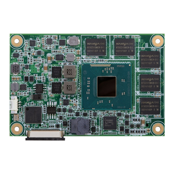
Chapter 3 Chapter 3 - Hardware Installation Block Diagram Board Layout LVDS PTN3460 LPC Bus LPC Bus Intel Atom SLP/LID Embedded System Fan PWM/TACH Controller IT8528 DDR3L 1GB C Bus CPU fan ECC 8x onboard DDR3 E3800 Series 1333MHz EEPROM Single Channel SM Bus Intel... -
Page 11: System Memory
Chapter 3 Important: System Memory Electrostatic discharge (ESD) can damage your board, processor, disk drives, add-in boards, and other components. Perform installation procedures at an ESD workstation only. If such a station is not available, you can provide some ESD protection by wear- ing an antistatic wrist strap and attaching it to a metal part of the system chassis. -
Page 12: Connectors
Chapter 3 Connectors COM Express Connector The COM Express connector is used to interface the BT9A3 Series COM Express board to a CPU Fan Connector carrier board. Connect the COM Express connector (lcoated on the solder side of the board) to the COM Express connector on the carrier board. - Page 13 Chapter 3 COM Express Connector Row A Row B Row A Row B Row A Row B Row A Row B GND (FIXED) GND (FIXED) RSVD RSVD GND (FIXED) GND (FIXED) RSVD VCC_5V_SBY GBE0_MDI3- GBE0_ACT# AC/HDA _BITCLK B32 SPKR GPO2 eDP_HPD VCC_5V_SBY GBE0_MDI3+...
-
Page 14: Com Express Connector Signal Discription
I/O Bi-directional input / output signal OD Open drain output AC97/HDA Signals Descriptions Signal Pin# Pin Type Pwr Rail /Tolerance BT9A3 Series Carrier Board Description AC/HAD_RST# O CMOS 3.3V Suspend/3.3V Connect to CODEC pin 11 RESET# Reset output to CODEC, active low. - Page 15 Chapter 3 PCI Express Lanes Signals Descriptions Signal Pin# Pin Type Pwr Rail /Tolerance BT9A3 Series Carrier Board Description PCIE_RX2+ Device - Connect AC Coupling cap 0.1uF I PCIE AC coupled off Module PCI Express Differential Receive Pairs 2 PCIE_RX2-...
- Page 16 Chapter 3 USB Signals Descriptions Signal Pin# Pin Type Pwr Rail /Tolerance BT9A3 Series Carrier Board Description USB0+ Connect 90 @100MHz Common Choke in series I/O USB 3.3V Suspend/3.3V USB differential pairs 0 and ESD suppressors to GND to USB connector...
- Page 17 Chapter 3 LVDS Signals Descriptions Signal Pin# Pin Type Pwr Rail /Tolerance BT9A3 Series Carrier Board Description LVDS_A0+ Connect to LVDS connector O LVDS LVDS LVDS_A0- LVDS_A1+ Connect to LVDS connector O LVDS LVDS LVDS_A1- LVDS Channel A differential pairs...
- Page 18 Chapter 3 Miscellaneous Signal Descriptions Signal Pin# Pin Type Pwr Rail /Tolerance BT9A3 Series Carrier Board Description I2C_CK I/O OD CMOS 3.3V Suspend/3.3V PU 2.2K to 3V3A_EC General purpose I2C port clock output I2C_DAT I/O OD CMOS 3.3V Suspend/3.3V PU 2.2K to 3V3A_EC General purpose I2C port data I/O line Output for audio enunciator - the "speaker"...
- Page 19 Chapter 3 GPIO Signals Descriptions Signal Pin# Pin Type Pwr Rail /Tolerance BT9A3 Series Carrier Board Description GPO0 GPO1 O CMOS 3.3V / 3.3V General purpose output pins. GPO2 GPO3 GPI0 PU 100K to 3.3V GPI1 PU 100K to 3.3V...
Need help?
Do you have a question about the BT9A3 Series and is the answer not in the manual?
Questions and answers