Table of Contents
Advertisement
edition
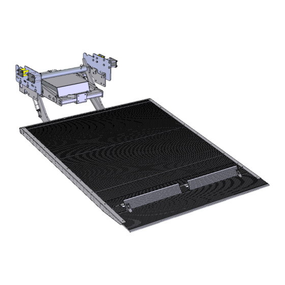
DH-LSP.07 500-750 kg
INSTALLATION MANUAL
Manufacturer:
DHOLLANDIA N.V.
Zoomstraat 9
9160 LOKEREN (Belgium)
Tel : +32 (0)9 349 06 92
Fax : +32 (0)9 349 09 77
e-mail : info@dhollandia.be
website : www.dhollandia.com
Read the operation manual in its entirety before operating the tail lift.
Read this installation manual in its entirety before installing the tail lift.
Order ref : xxx Doc: FIT_EUR installation manual LSP.07_EUR EN_2021
Rev: 0 Date: MARCH 29, 2021
Advertisement
Table of Contents

Subscribe to Our Youtube Channel
Related Manuals for Dhollandia DH-LSP.07


Summary of Contents for Dhollandia DH-LSP.07
- Page 1 DH-LSP.07 500-750 kg INSTALLATION MANUAL Manufacturer: DHOLLANDIA N.V. Zoomstraat 9 9160 LOKEREN (Belgium) Tel : +32 (0)9 349 06 92 Fax : +32 (0)9 349 09 77 e-mail : info@dhollandia.be website : www.dhollandia.com Read the operation manual in its entirety before operating the tail lift.
-
Page 2: Table Of Contents
Electric and hydraulic requirements ..........................59 17.4 Grease plans ..................................61 17.5 Connections to the main external control box type 1 ......................65 17.7 Safe operator position on the platform ..........................69 17.8 Wireless remote controls – generation 2020 ........................70 DHOLLANDIA... - Page 3 17.9 End note .................................... 72 17.10 Basic wiring diagrams ............................... 72 DHOLLANDIA...
-
Page 4: Understanding Safety And Warning Signs
Many safety signs and symbols used in this manual are based on international standards, others refer to specific situations or actions. Consult appendix 17.1 on page 56 for an overview of signs and symbols used in DHOLLANDIA manuals, and their meaning. Make sure you understand these signs and symbols prior to starting the installation. ... -
Page 5: Introduction, Contact Info And Disclaimers
It contains general instructions applicable to the most common types of factory built panel vans. Possibly, specific issues particular to your case are not adequately covered by this manual. If in doubt, contact your national DHOLLANDIA distributor for further assistance prior to continuing. -
Page 6: Safety Precautions For Operation
Safety instructions are a matter of progressive insight. The basics are listed in this manual, but contact the national DHOLLANDIA distributor for a copy of the latest set of instructions [see contact info on page 4], or download the latest edition from the DHOLLANDIA website: www.dhollandia.com →... - Page 7 DHOLLANDIA tail lift. In case of doubt, ALWAYS contact the national DHOLLANDIA distributor for further advice, prior to continuing. ALWAYS wear appropriate Personal Protective Equipment. This includes but may not be limited to: safety glasses with side guards or a wrap-around face shield;...
-
Page 8: Tail Lift Terminology
DHOLLANDIA tail lifts are designed as a bolt-on system, and don’t require any welding. See appendix 17.2 on page 58 for prescribed torque values. If for any reason, trouble-shooting and / or repair might be needed during the installation process, consult and follow the guidelines and safety instructions of the MAINTENANCE MANUAL. -
Page 9: Getting Started
Make sure planned modifications to the vehicle chassis and body will not adversely affect the strength and integrity of the vehicle. If the instructions of vehicle manufacturer conflict with the installation instructions issued by DHOLLANDIA (e.g. on fuse ratings, etc.), contact your national DHOLLANDIA distributor for further advice. See contact info on page 4. ... -
Page 10: General Installation Guidelines
The INSTALLATION DRAWINGS of the dedicated mounting plates are sent via the order confirmation. Make sure you have the correct installation instructions before starting. If not, contact your national DHOLLANDIA distributor for a copy of the relevant instructions. See contact info on page 4. -
Page 11: Preparation Of The Vehicle Chassis And Tail Lift
If the actual dimensions go outside the maximum installation parameters, DO NOT continue and contact your national DHOLLANDIA distributor for further advice. See contact info on page 4. Verify if you have the correct mounting plates for the job. Determine the scope of the work to firstly mount the mounting plates to the vehicle chassis, secondly to mount the lift frame to the mounting plates. - Page 12 These bolts are mechanical stops for the lift arms and determine the maximum lifting height of the platform. WARNING NEVER modify DHOLLANDIA tail lifts or their mounting plates, NEVER deviate from the described installation procedures without prior written consent by the manufacturer.
-
Page 13: Installation Of The Mounting Plates
REGULAR GUIDELINES The INSTALLATION DRAWINGS explaining how to bolt the quick-fit mounting plates to the vehicle chassis, are issued upon order confirmation, or can be obtained from your national DHOLLANDIA distributor. See contact info on page 4. For certain brands and types of chassis, the mounting plates use original holes only. - Page 14 ALWAYS use reinforcement tubes whenever instructed to do so or whenever they are included in the bolt kit of the tail lift. All metal works (drilling, cutting, grinding) to the chassis, subframe, rear cross member and vehicle body require adequate anti-corrosion protection. DHOLLANDIA...
- Page 15 See appendix 17.2 on page 58. If you use mounting bolts not supplied by DHOLLANDIA, obtain confirmation of the required torque from your supplier and make sure they guarantee at least an equivalent strength.
- Page 16 INSTALLATION DRAWING. Fasten the mounting bolts with the required torque by means of a torque wrench. Perform an equal installation on the left and right side The mounting plates can now receive the lift frame. DHOLLANDIA...
-
Page 17: Reinforcement Tubes Inside The Chassis
Insert the reinforcement tubes into the chassis, fit the mounting plates into correct position, mount the bolts, washers and nuts through the chassis and mounting plates and fasten them with the required torque by means of a torque wrench. See appendix 17.2 on page 58. DHOLLANDIA... -
Page 18: Mounting Of The Lift Frame
Raise the lift frame. Bring the holes in the mounting plates on the lift frame in line with the holes in the plates already mounted on the chassis. Mount the mounting bolts and nuts in accordance with the INSTALLATION DRAWING. DHOLLANDIA... - Page 19 The following steps require electric power to the tail lift. Connect the red (+) battery cable and the black (-) earth cable to an auxiliary battery pack. Or refer to 12.2 on page 37 for the permanent installation of the (+) battery and (-) earth cable. DHOLLANDIA...
-
Page 20: Towing Hitch
Bumper bar and towing hitches must be installed according to DHOLLANDIA’s instructions, and all bolts fastened with the required torque [see Annex 17.2 on page 58]. It is not allowed to modify these constructions without prior written approval from DHOLLANDIA. -
Page 21: Mounting Of The Platform
ALWAYS observe the safety instructions and precautions contained in the GENERAL SAFETY INSTRUCTIONS FOR INSTALLATION, MAINTENANCE AND REPAIR manual. ALWAYS keep hands clear of the moving items on the platform and on the lift frame. In case of doubt, contact the national DHOLLANDIA distributor for further assistance. DHOLLANDIA... - Page 22 Start at the left side. Slide the dia. 25 mm bar in the side channel of the platform until it hits the articulation pin inside. Then turn the bar clockwise to screw the M10 bolt in the thread foreseen in the articulation pin. DHOLLANDIA...
- Page 23 Remove the grease nipple and the locking bolt from the right side articulation pin. When the grease nipples and locking bolts are removed, retract the 2 articulation pins far enough to open up the cut- outs for the lift arms in the platform profile. DHOLLANDIA...
- Page 24 While doing so, ALWAYS make sure that you keep the platform, the hoist, clamp, slings etc. clear of the rear doors, to avoid damage. Also beware that you don’t damage the tilt cylinder, the safety valves, flexible pipes and cables that connect the lift frame with the platform. DHOLLANDIA...
- Page 25 Use the dia. 25 mm bar to push the articulation pin back inside the bottom platform profile and through the lift arm. Refer to the mark you have made on the pins to stop a the correction position. DHOLLANDIA...
- Page 26 Use the dia. 25 mm bar to push the articulation pin further back inside the bottom platform profile, through the lift arm and through the tilt cylinder bracket. Refer to the mark you have made on the pins to stop a the correction position. DHOLLANDIA...
- Page 27 See appendix 17.2 on page 58. When the grease nipples, the locking bolts and nuts are properly mounted and fastened with the required torque, retract the dia. 25 mm bars from the channel in the bottom platform profile. DHOLLANDIA...
-
Page 28: Stabilizer Arm
Manually pull down the bottom end of the tilt cylinder and swing down the tilt cylinder bracket. Bring the eye in the stabilizer arm in line with the eyes in the tilt cylinder bracket. DHOLLANDIA... -
Page 29: Tilt Cylinder: Hydraulic Hose And Electric Wiring
Swap over the banjo coupling to the other side if that provides a better fitting. Put the cupper O-rings back as you dismounted them from the flexible hose before: at least 1 on either side of the coupling of the hose. DHOLLANDIA... - Page 30 The pipe clamp should not be fully tigthened to remove all movement. Enable the clamp to rotate slightly in function of the position of the flexible hose during the various platform movements. Mount the plug of the safety valve on its coil and fasten the locking ring hand-tight. DHOLLANDIA...
- Page 31 But DO NOT overtighten the locking nut holding the pipe clamp shut.DO NOT remove all movement of the pipe clamp. Enable the clamp to rotate slightly in function of the position of the flexible hose during the various platform movements. DHOLLANDIA...
-
Page 32: Tilt Cylinder: End Stop And Adjustments
ALWAYS observe the safety instructions and precautions contained in the GENERAL SAFETY INSTRUCTIONS FOR INSTALLATION, MAINTENANCE AND REPAIR manual. In case of doubt, contact the national DHOLLANDIA distributor for further assistance. Carefully operate CLOSE to bring the platform in an almost vertical position. - Page 33 If a hinged bridge plate [option OAM008] is used, set the platform approx 10 mm lower than the vehicle floor. This will provide a smoother passage between the vehicle floor and the platform in use. DHOLLANDIA...
- Page 34 Contact your national DHOLLANDIA distributor if this risk exists. See contact info on page 4. LOWER the platform 100 mm and LIFT it again until you hear the hydraulic system turn in overpressure.
- Page 35 OPEN the platform again to do further adjustments. After final adjustment, turn the locking nur clockwise and fasten it tightly against the extension. Raise the rubber gaiter back up in its original position and fasten the collar. DHOLLANDIA...
- Page 36 Fasten the lower locking nut firmly with the required torque. See appendix 17.2 on page 58. Make sure the platform is firmly stabilized in the travel position. Try to rock it forwards and backwards by hand. Increase the eye bolt tension if not yet satisfactory. DHOLLANDIA...
-
Page 37: Electrical Installation
4 = main external control box 7 = electric motor 1 = (+) battery cable 5 = main battery disconnect switch 8 = cabin switch 2 = (-) earth cable 6 = starter solenoid 3 = 12 or 24V battery DHOLLANDIA... -
Page 38: Installation Of The (+) Battery And (-) Earth Cable
The instructions below showcase one type of vehicle. The explained methods and procedures apply however to installations on all types of vehicles. In case of doubt, contact your national DHOLLANDIA distributor. See page 4 for contact info. Mount protective conduits over the full length of the (+) battery cable and the (-) earth cables. - Page 39 Search for an adequate entry for the (+) battery cable and (-) earth cable into the battery compartment. Most types of vans are equipped with a dedicated rubber diaphragm to pass wires from the chassis area to inside the battery compartment or vehicle cabin. DHOLLANDIA...
- Page 40 Slide 2 bits of 100 mm heat shrink over the cable eye connections. Use a heat gun to wrap the heat shrink over the cable and the cable eyes. Connect the cable eyes to the studs of the main battery disconnect switch and fasten the M8 bolts with the required torque. DHOLLANDIA...
- Page 41 This fuse should have a min. rating of 200A. In case of doubt, contact the vehice importer or DHOLLANDIA for further advice. See contact info on page Mount the cable eye to the end of the (-) earth cable.
-
Page 42: Cabin Switch
Carefully cut the 2 slots in the side panel of the vehicle body. Deburr the cut-outs. Apply masking tape around the cut-outs, within the outside dimensions of the front covers of the control boxes. Apply adequate anti-corrosive protection to the freshly made cuts and allow to dry. DHOLLANDIA... - Page 43 Mount a protective conduit over the full length of the cable. Attach the cable with cable ties at min. 200 mm intervals. Enter the cable into the power pack, either via the multi- cable entry seal or via one of the single cable glands. DHOLLANDIA...
- Page 44 DO NOT operate LIFT or CLOSE while the power pack is hanging open. The hydraulic pump might suck air and a purge of the pump might be required when neglecting this NOTICE. ALWAYS close the power pack prior to LIFTING / CLOSING the platform. DHOLLANDIA...
-
Page 45: Wireless Control Unit
The 3-button wander lead with spiral cable [option OAE046.2] is usually stored inside the vehicle cabin. Test all functions of the wireless control and the 3-button wander lead with spiral cable. DHOLLANDIA... -
Page 46: License Number Plate Light [Option Oae210]
Refer FITTING BODY BUILDING INSTRUCTIONS of the vehicle manufactuer for further detail. Or instruct the manufacturer’s dedicated workshop to make this connection. Switch on the vehicle lights. Test the license number plate light installed on the platform. DHOLLANDIA... -
Page 47: Intallation Of Extra Controls
Read and follow the instructions FIT-ELEC-OPTION-… (latest update). If not supplied with the tail lift, these can be downloaded from the “DOWNLOAD” section on our website: www.dhollandia.com → Country & language selection → Downloads → Mounting instructions → General → … select required manual ... -
Page 48: Putting The Tail Lift Into Service
2. LOWER the platform fully to the lowest point and press LOWER for extra 20 sec. LIFT the platform again and repeat until no more air bubbles back to the oil reservoir. DHOLLANDIA... - Page 49 In case of a regular installation with rear doors, determine the adequate position for the bridge plate [option OAM008]. Cut the bridge plate to the desired width. Mount the bridge plate to the vehicle floor. DHOLLANDIA...
-
Page 50: Lubrication Instructions
Refer to appendix 17.4 from page 61 onwards for the relevant grease plan of the tail lift, or download any from the website: www.dhollandia.com → Country & language selection → Downloads → Maintenance & Repair → Grease plans → … select required plan EXAMPLE ... -
Page 51: Quality Control And Pdi Test
Refer to the CE IDENTIFICATION AND INSPECTION LOGBOOK. Work through the CHECKLIST FOR THE PRE-DELIVERY INSPECTION (PDI) TEST. Complete the practical tests indicated therein. Fill-out the FITTING DECLARATION. DHOLLANDIA... - Page 52 Adjust the pressure if too high or too low, seal the pressure relief valve after that. If in doubt how to adjust the pressure relief valve, refer to procedure I-SERV-G-003 of the MAINTENANCE AND REPAIR MANUAL, or contact your national DHOLLANDIA distributor for help. See contact info on page 4. DHOLLANDIA...
- Page 53 Verify and make sure the vehicle floor doesn’t flex or distort while performing the dynamic weight test. Check and retighten the mounting bolts and nuts after the static and dynamic weight test performed during the pdi test. DHOLLANDIA...
-
Page 54: Decals
Affix the safety decals to the tail lift and vehicle body in accordance with the instructions below. Note: the decals marked as “EXAMPLE” can vary in function of the maximum rated capacity of the tail lift, or the chosen type of external control box. DHOLLANDIA... - Page 55 ❶ ❷ ❸ ❹ xxxx ❺ ❻ DHOLLANDIA...
- Page 56 ❼ ❽ ❾ Tail lift decals used and affixed in areas, other than the rear of the vehicle. ❶ Cabin switch in driver’s cabin to switch electrical power to tail lift on / off (if so equipped) DHOLLANDIA...
-
Page 57: Appendix
17.1 MEANING OF THE SAFETY AND WARNING SIGNS WARNING signs MANDATORY ACTION signs Overview and keep visual control over the Contact your regional DHOLLANDIA distributor. working area of the tail lift at all times. General warning sign used to alert the user to Consult the DHOLLANDIA website. - Page 58 / or Switch between external and internal controls. cabin switch. This is an operation to be executed manually (as opposed to an electrical function controlled by means of one of the control units). DHOLLANDIA...
-
Page 59: Prescribed Torque Values For Bolts And Nuts
A fall of the tail lift off the chassis can damage the tail lift and / or vehicle chassis and can cause serious bodily injury or death to the operator and any bystanders. Therefore, it is essential that the mounting plates are installed following the instructions of this manual. DHOLLANDIA... -
Page 60: Electric And Hydraulic Requirements
The applicable wiring diagrams are stored at the inside of the main external control box. A copy of the wiring diagrams can also be obtained from the national DHOLLANDIA distributor [see contact info on page 4]; or downloaded from the DHOLLANDIA website: www.dhollandia.com →... - Page 61 It is important to follow these guide-lines with due care. A lot of oils or fluids used in automotive industry, such as transmission fluids and ATF oils, are not suitable for tail lift use. DHOLLANDIA has not tested the potential consequences of oils and fluids with deviating specifications and cannot be held responsible or legally liable for any damage to the tail lift caused by the replenishment with non- compatible oils or fluids;...
-
Page 62: Grease Plans
This annex includes grease plans for the most frequent tail lifts DH-LSP* 500-1000 kg. A copy of the grease plans can also be obtained from the national DHOLLANDIA distributor [see contact info on page 4]; or downloaded from the DHOLLANDIA website: www.dhollandia.com →... - Page 63 DHOLLANDIA...
- Page 64 DHOLLANDIA...
- Page 65 DHOLLANDIA...
-
Page 66: Connections To The Main External Control Box Type 1
Reserve the wider for the ticker channels.. supplied with the tail lift. battery & earth cables. Use the narrower for control units, cables of safety valves Route the cable in such a way that it etc. cannot be damaged or pinched. DHOLLANDIA... - Page 67 Prepare to place the top element [1] back Slide the top element [1] back in the cut-out foreseen in the back plate of the power on top of the bottom element [2]. pack, and press it hard against the back plate. DHOLLANDIA...
- Page 68 Finish off the multi-cable entry seal as battery cable to the incoming terminal of of the main battery disconnect switch by explained above for the case without the main battery disconnect switch. means of a hexagonal key nr. 13. main battery disconnect switch. DHOLLANDIA...
- Page 69 Insufficient torqueing of the connection bolts can cause overheating and short circuits. Improper sealing can cause water ingress, and premature corrosion of the connections. DHOLLANDIA disclaims liability for any personal injury or property damage that results from improper or negligent installation. DHOLLANDIA...
-
Page 70: Safe Operator Position On The Platform
3 points of contact while travelling on the platform, in accordance with the operation manual. The handgrip is normally foreseen by the body builder as part of the design of the body. A DHOLLANDIA alternative can be ordered with spare part ref. M1406. -
Page 71: Wireless Remote Controls - Generation 2020
OPEN / CLOSE function to continue. The wireless remote control incorporates various modes adapted to the functional logic and wiring diagram of the tail lift. Follow the instructions below to changes modes. DHOLLANDIA... - Page 72 LOWER (button 5) Mode 4 HYDR + safety stop LIFT + ON (button 2 + 3) CLOSE + OPEN (button 1+4) Back to default mode 1 MECH.X / OMM6 LIFT + ON (button 2 + 3) CLOSE (button 1) DHOLLANDIA...
- Page 73 17.9 END NOTE DHOLLANDIA would like to thank you for using our products and leave you with this final notice and warning. Additional information about this tail lift and many other DHOLLANDIA products is available at the following link: http://www.dhollandia.com/...
Need help?
Do you have a question about the DH-LSP.07 and is the answer not in the manual?
Questions and answers