
Related Manuals for Parker ACR1505


Summary of Contents for Parker ACR1505
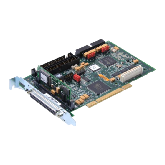
- Page 1 (217) 352-9330 | Click HERE Find the Parker / Compumotor ACR1505 at our website:...
- Page 2 Artisan Technology Group - Quality Instrumentation ... Guaranteed | (888) 88-SOURCE | www.artisantg.com...
- Page 3 Failure to do so can result in damage to equipment and/or serious injury to personnel. ACR Series products and the information in this user guide are the proprietary property of Parker Hannifin Corporation or its licensers, and may not be copied, disclosed, or used for any purpose not expressly authorized by the owner thereof.
-
Page 4: Table Of Contents
Jumpers, Resistors, and Encoders .................... 7 Jumpers ........................... 7 Resistor Packs ......................... 8 Differential Encoders (Parker Drives and Encoders)............... 8 Single-Ended Encoders (not recommended) ................ 10 Configuring the Voltage Jumpers and Resistor Packs ............13 Encoder Input Connector (P1)....................14 Analog/Digital I/O—P2 Connector.................... - Page 5 Digital I/O..........................41 Input Signal ..........................41 Output Signal ......................... 41 High Speed Outputs ......................41 P3 & P4 Connector Specification—ACR1505 ............... 42 P3 & P4 Connector Specification—Mating Connector ............42 Cables ............................42 Fuses............................42 P1 Connector ......................... 42 P2 Connector .........................
- Page 6 Table of Tables Table 1 Ship Kit Items ........................ 5 Table 2 Jumper (JP1) Configuration for Encoder Voltage ............7 Table 3 Jumper (JP2) Configuration for Encoder Voltage ............8 Table 4 Resistor Packs and Voltage Jumpers ................8 Table 5 Resistor Pack and Voltage Jumper Configuration ............13 Table 6 P1 Connector Pinout ...............
- Page 7 Table of Figures Figure 1 Differential, Open Collector Encoder with internal pull-up resistors ......9 Figure 2 Differential, Line Driver Encoder with internal termination resistors ......10 Figure 3 Single-Ended Encoder with internal pull-up resistors ..........12 Figure 4 Single-Ended Encoder with external pull-up and pull-down resistors......13 Figure 5 P1 connector, male drive connector pinout ........
- Page 8 Warning! Do not install the ACR1505 in a computer that uses an AT power supply. Doing this will permanently damage the controller card. The ACR1505 is only compatible with ATX power supplies, which provide both +3.3 VDC and +5 VDC to the PCI bus.
-
Page 9: Important Information For Users
Since Parker Hannifin constantly strives to improve all of its products, we reserve the right to modify equipment and user guides without prior notice. No part of this user guide may be reproduced in any form without the prior consent of Parker Hannifin. -
Page 10: Change Summary
Change Summary Revision D Changes This document, 88-021610-01D, supercedes 88-021610-1C. Changes associated with ACR1505 User Guide revisions, and document clarifications and corrections are as follows: Topic Description High Speed outputs Added specifications for High-Speed Outputs, added to P2 Connector pinout. - Page 11 Artisan Technology Group - Quality Instrumentation ... Guaranteed | (888) 88-SOURCE | www.artisantg.com...
-
Page 12: Chapter 1 - Introduction
C H A P T E R O N E Introduction Chapter 1 – Introduction IN THIS CHAPTER • ACR1505 Products—Overview............. • Compatible Parker Products ..............• Requirements ..................• Checking Your Shipment ..............• Assumptions of Technical Experience ..........• Technical Support ................. -
Page 13: Acr1505 Products-Overview
The ACR1505 is a PC-bus based controller in the ACR family of high- performance motion controllers. As a half-length 32-bit PCI card, the ACR1505 can run up to four servo drives or stepper drives with up to four encoders. The 1505 controller has 16 fixed inputs, 16 fixed outputs, and an additional 16 configurable I/O points. -
Page 14: Acr1505 Names
ACR1505 Names The following helps explain the meaning of ACR1505 part numbers: 1505 Controller Type........ACR1505 PC Bus ............ PC = PCI Bus Card Encoder Inputs ........E0 = 0 Encoder Inputs E4 = 4 Encoder Inputs Motion Outputs........D4 00... -
Page 15: Requirements
Warning! Do not install the ACR1505 in a computer that uses an AT power supply. Doing this will permanently damage the controller card. The ACR1505 is only compatible with ATX power supplies, which provide both +3.3 VDC and +5 VDC to the PCI bus. -
Page 16: Checking Your Shipment
ACR SDK Compact Disc Table 1 Ship Kit Items Assumptions of Technical Experience The ACR1505 is designed for industrial applications. To effectively install and troubleshoot the ACR1505, you must have a fundamental understanding of the following: • Motion control applications •... -
Page 17: Chapter 2 - Hardware Configuration
C H A P T E R T W O Hardware Configuration Chapter 2 – Hardware Configuration IN THIS CHAPTER • Overview—Configuring the Hardware ..........• Jumpers, Resistors, and Encoders ............• Encoder Input Connector (P1) ............• Analog/Digital I/O—P2 Connector............•... -
Page 18: Overview-Configuring The Hardware
• Resistor packs RP1 through RP4 Jumpers The ACR1505 can supply +5 VDC or +12 VDC to each encoder. Use Table 2 and Table 3 to determine the correct jumper configurations. For the location of the jumpers, see Figure 14 on page 28. -
Page 19: Resistor Packs
Table 3 Jumper (JP2) Configuration for Encoder Voltage Resistor Packs The ACR1505 comes with termination resistor packs installed. If using open collector or single ended encoders (not recommended), you must replace the packs. For more information, see “Differential Encoders (Parker Drives and Encoders)”. -
Page 20: Figure 1 Differential, Open Collector Encoder With Internal Pull-Up Resistors
Warning! When using pull-up resistor packs (necessary with open collector encoders), the ACR1505 is not able to detect encoder failures. An encoder fault can occur, but the ACR1505 Controller is unable to notify the user. For a wiring schematic, see Figure 1. -
Page 21: Single-Ended Encoders (Not Recommended)
Single-Ended Encoders (not recommended) Single-ended encoders (encoders without the A–, B–, or Marker outputs) require specific setup. You can install pull-up resistors on the ACR1505, or you can install resistors external to the card. • Use only the positive (+) side of the differential input signal for the encoder signal connection. - Page 22 (factory installed) with common, 8-pin, 1 KΩ pull-up resistor packs. Warning! When using pull-up resistor packs (necessary with open collector encoders), the ACR1505 is not able to detect encoder failures. An encoder fault can occur, but the ACR1505 Controller is unable to notify the user. Configuration 1 This configuration provides pull-up resistors on the ACR1505, and external pull-down resistors for the encoder input signals.
-
Page 23: Figure 3 Single-Ended Encoder With Internal Pull-Up Resistors
3. On the negative ( – ) side of the differential signal, install an external pull-up resistor. • For +5 VDC encoders, install common 1 KΩ, 8-pin pull-up resistor packs. Continued on next page – 12 – ACR1505 User’s Guide Artisan Technology Group - Quality Instrumentation ... Guaranteed | (888) 88-SOURCE | www.artisantg.com... -
Page 24: Configuring The Voltage Jumpers And Resistor Packs
Setting Differential Line Driver Configure JP1 and JP2 for Termination resistor packs (+5 VDC Outputs) +5 VDC (factory installed) (Parker Drives and Encoders) Open Collector Driver Configure JP1 and JP2 for Common pull-up resistors (No pull-ups on encoder) +12 VDC... -
Page 25: Encoder Input Connector (P1)
Pre-quadrature frequency ....... 7.5 MHz Post-Quadrature Frequency ....30 MHz Current per Channel ....... 100 mA, maximum; not to exceed 400 mA for four encoders. – 14 – ACR1505 User’s Guide Artisan Technology Group - Quality Instrumentation ... Guaranteed | (888) 88-SOURCE | www.artisantg.com... -
Page 26: Table 6 P1 Motor Feedback Connector Pinout
P1 Connector Pinout Signal Description CHA0+ Encoder A Channel in CHA0– Encoder A Channel in CHB0+ Encoder B Channel in CHB0– Encoder B Channel in ENC0+/MRK0+ Encoder Z Channel in ENC0–/MRK0– Encoder Z Channel in +5 VDC (100 mA, max) * +5 VDC Encoder power Encoder Power Return CHA1+... -
Page 27: Analog/Digital I/O-P2 Connector
Inputs and outputs for the drive’s analog connections are located on the I/O connector. ANALOG Note: For an ACR1505 Controller with two servo and two stepper axes, the servo signals are sent across channels zero and one, and the stepper signals are sent across channels two and three. -
Page 28: Figure 7 P2 Analog I / O Connector-Internal Circuit Diagram
Figure 7 P2 connector—internal circuit diagram ANALOG I Figure 8 P2 connector—internal circuit diagram STEPPER I Figure 9 P2 H connector—internal circuit diagram PEED OUTPUT Chapter 3 – Hardware Installation – 17 – Artisan Technology Group - Quality Instrumentation ... Guaranteed | (888) 88-SOURCE | www.artisantg.com... - Page 29 AIN 3 * ADC Input AIN 5 * ADC Input AIN 7 * ADC Input +5 VDC +5 VDC power supply (0.250A max) – 18 – ACR1505 User’s Guide Artisan Technology Group - Quality Instrumentation ... Guaranteed | (888) 88-SOURCE | www.artisantg.com...
-
Page 30: Table 7 P2 Analog I/O Connector Pinout
I/O Connector Pinout ANALOG Watchdog Signal The watchdog provides a digital signal to monitor the health of the ACR1505 controller. When a fault occurs, the watchdog disables all connected drives. You must manually clear the fault and reset the controller. -
Page 31: Digital I/O-P3 & P4 Connectors
Digital I/O—P3 & P4 Connectors The ACR1505 has two 50-Pin headers (P3 and P4) for TTL compatible Digital I/O. Both connectors are Opto-22 compatible. There are 48 software configurable I/O points, which you can group as follows: • 24 inputs and 24 outputs •... -
Page 32: P3 Connector Pinout
P3 Connector Pinout Inputs and outputs for the controller’s digital connections are located on the connector. DIGITAL I Figure 11 P3 connector diagram DIGITAL I P3 Connector Pinout Signal Signal I/O 47 I/O 46 I/O 45 I/O 44 I/O 43 I/O 42 I/O 41 I/O 40... -
Page 33: P4 Connector Pinout
I/O 5 I/O 4 I/O 3 I/O 2 I/O 1 I/O 0 +5 VDC (1A, max) Table 10 I/O Connector Pinout DIGITAL – 22 – ACR1505 User’s Guide Artisan Technology Group - Quality Instrumentation ... Guaranteed | (888) 88-SOURCE | www.artisantg.com... -
Page 34: I/O Configuration Modes And The P3 Connector
I/O Configuration Modes and the P3 Connector Factory Default........I/O Configuration Mode 0 I/O Config I/O Config I/O Config Mode 0 Mode 1 Mode 2 I/O-47 OUT55 INP31 OUT55 I/O-46 OUT54 INP30 OUT54 I/O-45 OUT53 INP29 OUT53 I/O-44 OUT52 INP28 OUT52 I/O-43 OUT51... -
Page 35: I/O Configuration Modes And The P4 Connector
I/O-01 INP1 INP1 INP1 I/O-00 INP0 INP0 INP0 +5 VDC (1A, max) Table 12 P4 Connector Pinout and I/O Mode Configuration – 24 – ACR1505 User’s Guide Artisan Technology Group - Quality Instrumentation ... Guaranteed | (888) 88-SOURCE | www.artisantg.com... -
Page 36: Address Jumper For Serial Communication
ACR1505 numbers. Use Table 13 to determine the jumper configuration necessary to assign a communication address. Important! Do not assign number 15 to an ACR1505 unless you want to put it in Flash Bypass Mode. For more information, see “Flash Bypass Mode”. -
Page 37: Chapter 3 - Hardware Installation
C H A P T E R T H R E E Hardware Installation Chapter 3 – Hardware Installation IN THIS CHAPTER • Environment & Cooling ............... • Weight ....................• Dimensions..................• Hardware Installation ................Artisan Technology Group - Quality Instrumentation ... Guaranteed | (888) 88-SOURCE | www.artisantg.com... -
Page 38: Environment & Cooling
Environment & Cooling The ACR1505 operates in an ambient temperature range of 0°C (32°F) to 45°C (113°F). The controller can tolerate atmospheric pollution degree 2— only dry, non-conductive pollution is acceptable. Therefore, it is recommended that the card be mounted in a suitable enclosure. The ACR1505 is designed for mounting in a PC (personal computer)—you should... -
Page 39: Dimensions
Dimensions Card Dimensions........4.200” x 6.875” Figure 13 Dimensions Connectors Figure 14 Connector, Jumper, and Fuse Locations – 28 – ACR1505 User’s Guide Artisan Technology Group - Quality Instrumentation ... Guaranteed | (888) 88-SOURCE | www.artisantg.com... -
Page 40: Hardware Installation
Warning! Do not install the ACR1505 in a computer that uses an AT power supply. Doing this will permanently damage the controller card. The ACR1505 is only compatible with ATX power supplies, which provide both +3.3 VDC and +5 VDC to the PCI bus. - Page 41 Warning! Do not install the ACR1505 in a computer that uses an AT power supply. Doing this will permanently damage the controller card. The ACR1505 is only compatible with ATX power supplies, which provide both +3.3 VDC and +5 VDC to the PCI bus.
- Page 42 Do not pull on the cable as you may damage it. • The ACR1505 is a sensitive device. Do not remove the card from its antistatic package until you are ready to install it in the computer.
-
Page 43: Installation Test
If motion is clockwise on an axis, send the command DACn GAIN +3276.8 (where n is the axis number). You should now see all servo axes moving in the counter clockwise direction. – 32 – ACR1505 User’s Guide Artisan Technology Group - Quality Instrumentation ... Guaranteed | (888) 88-SOURCE | www.artisantg.com... - Page 44 c. On the View menu, click Parameters. In the Parameter window, select Encoder 0..7 in the left list. You should see the encoders count in the negative direction. If n encoder is counting in the positive direction, then send the command ENCn MULT –4 (where n is the axis number).
-
Page 45: Chapter 4 - Troubleshooting
C H A P T E R F O U R Troubleshooting Chapter 4 – Troubleshooting IN THIS CHAPTER • First Troubleshooting Steps ..............• General Troubleshooting..............Artisan Technology Group - Quality Instrumentation ... Guaranteed | (888) 88-SOURCE | www.artisantg.com... -
Page 46: Troubleshooting Guidelines
Warning! Do not install the ACR1505 in a computer that uses an AT power supply. Doing this will permanently damage the controller card. The ACR1505 is only compatible with ATX power supplies, which provide both +3.3 VDC and +5 VDC to the PCI bus. -
Page 47: General Troubleshooting
IGAIN, ILIMIT, IDELAY, DGAIN, DWIDTCH, FFVEL, FFACC, and TLM=0 For more information, see “User’s Guide Part 1”. Continued on next page – 36 – ACR1505 User’s Guide Artisan Technology Group - Quality Instrumentation ... Guaranteed | (888) 88-SOURCE | www.artisantg.com... -
Page 48: Table 15 Troubleshooting-Causes And Solutions
Check if the commanded torque limit (TLM) is limit set at zero. Undesirable motion DAC GAIN using The ACR1505 hardware inverts the output voltage. Make sure you are using the correct incorrect value setting for your drive. A positive DAC GAIN physically sends out a negative voltage, and a negative DAC GAIN physically sends out a positive voltage. -
Page 49: Appendix A - Additional Specifications
A P P E N D I X A Additional Specifications Appendix A – Additional Specifications IN THIS CHAPTER • Hardware..................... • Power Consumption................• Encoder Inputs ..................• Analog I/O ................... • Digital I/O..................... • Fuses....................Artisan Technology Group - Quality Instrumentation ... Guaranteed | (888) 88-SOURCE | www.artisantg.com... -
Page 50: Hardware
Pre-quadrature frequency ....... 7.5 MHz Post-Quadrature Frequency ....30 MHz Current per Channel ....... 100 mA, maximum; not to exceed 400 mA for four encoders. P1 Connector Specification—ACR1505 Manufacturer ........... AMP or equivalent Connector Type........34-Pin Box Header (male connector) AMP Part Number ........ -
Page 51: Analog I/O
Manufacturer ........... AMP or equivalent Connector Type........34-Pin Receptacle (female connector) with strain relief AMP Part Number ........746285-8 Note: Mating connectors are not provided with the ACR1505. Parker cables are available with mating connectors attached. Analog I/O I/O Signal Signal High.......... -
Page 52: Digital I/O
Manufacturer ........... AMP or equivalent Connector Type........37-Pin High Density D-Subminiature (male connector) Gold flash AMP Part Number ........747916-4 Note: Mating connectors are not provided with the ACR1505. Parker cables are available with mating connectors attached. Digital I/O Input Signal Logic High .......... -
Page 53: P3 & P4 Connector Specification-Acr1505
Cables The total cable length between active components cannot exceed 13 feet. This applies to all cables for the ACR1505, as well as the ACRIO and EXPAXIS modules. Note: The RBC1505 Breakout Box is not an active component. - Page 54 Voltage ............ +5 VDC Current Rating......... 2A Type ............Littelfuse 454.002 Time Delay Fuse Appendix B – - 43 - Artisan Technology Group - Quality Instrumentation ... Guaranteed | (888) 88-SOURCE | www.artisantg.com...
-
Page 55: Appendix B - Breakout Box
A P P E N D I X B Breakout Box Appendix B – Breakout Box IN THIS CHAPTER • Breakout Box Overview............... • Checking your Shipment ..............• Breakout Box Dimensions..............• Environment & Cooling ............... • Breakout Box to User Interconnect ............. Artisan Technology Group - Quality Instrumentation ... -
Page 56: Breakout Box Overview
Maximum Power per Channel....100 mA Digital I/O Cables There are two 50-pin headers provided on the RBC1505-xx Breakout Box to interface Digital I/O signals to an ACR1505 Controller Card. The digital I/O use the 50-pin headers. Connections are as follows: •... -
Page 57: Environment & Cooling
Notes • Make sure the ambient air temperature entering the RBC1505-xx Breakout Box or rising up to the ACR1505 is within acceptable ambient temperature limits. • After installation, verify that the ambient air temperature directly below the top-most RBC1505-xx does not exceed the Ambient Operating Temperature. -
Page 58: Breakout Box Dimensions
Breakout Box Dimensions Figure 15 Breakout Box Dimensions Appendix B – Breakout Box - 47 - Artisan Technology Group - Quality Instrumentation ... Guaranteed | (888) 88-SOURCE | www.artisantg.com... -
Page 59: Breakout Box To User Interconnect
DGND DGND DGND RXD2B TXD2B Note: Use a standard Null Modem cable for COM connections. Table 19 COM2 Serial Port Connector – 48 – ACR1505 User’s Guide Artisan Technology Group - Quality Instrumentation ... Guaranteed | (888) 88-SOURCE | www.artisantg.com... -
Page 60: Drive Enable And Drive Reset
Axis connectors is ON. For Axis connector pinouts, see Table 22 on page 50. Note: Use the SET command to activate the appropriate outputs for each axis. DIP Switch SW1 RBC1505-xx Signal ACR1505 Controller Digital Out Axis (Bit) Drive Enable* Drive Reset Drive Enable... -
Page 61: Axis Connectors
Breakout Box. Connect only to pins 10 – 13, or pins 14 & 15; Do not connect to both. Table 22 Axis Connector Pinout – 50 – ACR1505 User’s Guide Artisan Technology Group - Quality Instrumentation ... Guaranteed | (888) 88-SOURCE | www.artisantg.com... - Page 62 PCI communications ........... 35 differential PCI computer "lock-up" ........35 line driver ............10 power ..............35 open collector ..........8 stepper motion ........... 36 – 51 – ACR1505 User’s Guide Artisan Technology Group - Quality Instrumentation ... Guaranteed | (888) 88-SOURCE | www.artisantg.com...
- Page 63 19 circuit ..............19 weight..............27 – 52 – ACR1505 User’s Guide Artisan Technology Group - Quality Instrumentation ... Guaranteed | (888) 88-SOURCE | www.artisantg.com...
Need help?
Do you have a question about the ACR1505 and is the answer not in the manual?
Questions and answers