Parker ACR7000 User Manual
Hide thumbs
Also See for ACR7000:
- User manual (60 pages) ,
- Hardware manual (21 pages) ,
- Programmer's manual (341 pages)

Subscribe to Our Youtube Channel
Related Manuals for Parker ACR7000


Summary of Contents for Parker ACR7000
- Page 1 User Guide ACR7000 Controller Effective: September 2020 Document Number: 88-033593-01A...
-
Page 2: User Information
Since Parker Hannifin constantly strives to improve all its products, we reserve the right to change this guide, and software and hardware mentioned therein, at any time without notice. -
Page 3: Eu Declaration Of Conformity
Adjustable speed electrical power drive systems – Part 3: EMC requirements and specific test methods The installation requirements are detailed in the User Guide supplied with the equipment. Year in which CE mark first affixed:2020 ACR7000 Controller Installation Guide 3... -
Page 4: Symbols
Warning: Risk of damage and/or personal injury. The ACR7000 Controller described in this guide contains no user- serviceable parts. Attempting to open the case of any unit, or to replace any internal component, may result in damage to the unit and/or personal injury. -
Page 5: Important Safety Information
The information in this user guide, including any apparatus, methods, techniques, and concepts described herein, are the proprietary property of Parker Hannifin or its licensors, and may not be copied disclosed, or used for any purpose not expressly authorized by the owner thereof. -
Page 6: Table Of Contents
Description ................................4 Important Safety Information...................... 5 Contents ............................6 CHAPTER 1 Introduction ......................9 ACR7000 Controller - Overview ....................10 Product Description..........................10 ACR7000 Part Numbers ........................10 Checking Your Shipment ......................11 Assumptions of Technical Experience ..................11 Technical Support ........................ - Page 7 Internal Encoder 8 Connections ......................38 Analog Inputs (- ANI Option) ....................40 Analog Input Pinout ..........................41 CHAPTER 4 Communications ....................44 Overview ............................45 Ethernet Specifications ....................... 45 Ethernet Cable Specification ......................... 45 Ethernet Connector ..........................45 ACR7000 Controller Installation Guide 7...
- Page 8 Basic Operation ........................... 53 Parker Motion Manager ......................... 53 Configuration Wizard ............................53 Memory ..................................57 Appendix A Accessories ......................58 Controller to Drive Cables ......................59 VM26 Breakout Module ......................60 VM25 Breakout Module ......................61 8 ACR7000 Controller Installation Guide...
-
Page 9: Chapter 1 Introduction
INTRODUCTION CHAPTER 1 Introduction ACR7000 Controller Installation Guide 9... -
Page 10: Acr7000 Controller - Overview
INTRODUCTION ACR7000 Controller - Overview The ACR7000 Controller, part of the ACR7000 family, is a multi-axis motion controller. Setup and programming are accomplished using the AcroBASIC language within the Parker Motion Manager programming environment. Product Description The ACR7000 Controller shares the control capability and ACROBasic programming language with the ACR7000 family of controllers and integrated drive products. -
Page 11: Checking Your Shipment
Confirm that you have received all items in the table below. If you are missing an item, call the factory. For contact information, see Contact Information for Technical Assistance at the beginning of this guide. The following items ship with the ACR7000 Controller. The connectors are inserted in the controller during shipment and are not packaged separately. -
Page 12: Chapter 2 Mechanical Installation
MECHANICAL INSTALLATION CHAPTER 2 Mechanical Installation 12 ACR7000 Controller Installation Guide... -
Page 13: Environment & Drive Cooling
Therefore, it is recommended that the product be mounted in a suitable enclosure. For proper cooling, the ACR7000 must be installed so that the cooling vents allow for vertical air flow. Figure 3 on page 17 shows the mounting orientation, as well as the minimum top, bottom, and side installation clearances. -
Page 14: Dimensions
MECHANICAL INSTALLATION Dimensions Figure 1. - ACR74C Dimensions Figure 2. - ACR78C Dimensions 14 ACR7000 Controller Installation Guide... -
Page 15: Mounting Orientation
MECHANICAL INSTALLATION Mounting Orientation The ACR7000 should be mounted to a vertical surface in the orientation shown below to allow for vertical air flow through the cooling vents on the top and bottom of the product Consult factory to review applications where vertical mounting is not possible. -
Page 16: Weight
EN 61800-3 ed2.0. Cable Routing Route high power cables (motor and mains) at right angles to low power cables (communications and inputs/outputs). Never route high and low power cables parallel to each other. 16 ACR7000 Controller Installation Guide... -
Page 17: Chapter 3 Electrical Installation
ELECTRICAL INSTALLATION CHAPTER 3 Electrical Installation ACR7000 Controller Controller Installation Guide 17... -
Page 18: Installation Safety Requirements
ELECTRICAL INSTALLATION Installation Safety Requirements The ACR7000 Controller has been shown to meet the CE requirements for Electromagnetic Compatibility (IEC 61800-3 ed2.0 per 204/108/EC) when installed, operated and maintained as described in the product User Guide. As a rule, it is recommended that the ACR7xC be installed in an enclosure to protect it from atmospheric contaminants and to prevent operator access while power is applied. -
Page 19: System Installation Overview
This section details the components and configuration necessary for electrical installation of the ACR7000 Controller. Installation of a motion control system requires an ACR7000, one or more compatible drive and motor 24VDC Power Supplier and access to a computer. Refer to the following figure for a diagram of this system. -
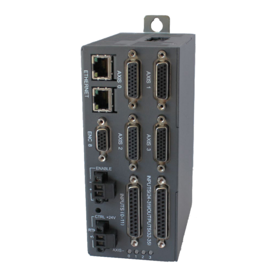
Page 20: Connectors
ELECTRICAL INSTALLATION Connectors Connector specifications are in this section. The following figure shows the name and location of the connectors. Figure 5. - ACR74C Connectors 20 ACR7000 Controller Installation Guide... -
Page 21: Ctrl - Control Power Connector
Reverse Polarity, Overvoltage The power required for the control input depends on what external devices are supplied through the controller. Warning: To avoid possible memory corruption, do NOT cycle power during FLASH memory operations ACR7000 Controller Controller Installation Guide 21... -
Page 22: Control Power Led
The Control power LED indicates the operating status of the controller. Note: LED does not have a plastic lens cover. Open hole in sheet metal exposes LED on internal circuit board Color Status Control Power is off. Booting (less 2 seconds) Green Ready 22 ACR7000 Controller Installation Guide... -
Page 23: Enable - Enable Input Connector
ENABLE – Enable Input Connector The Enable Input must be connected to 24VDC in order to enable external drives and provide command signals. If the input goes inactive, that inactive state is latched and the ACR7000 reacts by doing the following: •... -
Page 24: Axis Connectors
The ACR7000 controllers employ a single connector that handles both the encoder and drive signals—the Axis connector. Depending on the configuration of the ACR7000 controller, there are four or eight axis connectors on the front panel. They are labeled AXIS 0 through AXIS 7. The axis connector is a 26-pin, female D-sub, high- density connector. -
Page 25: Axis Connector Pinout
5VDC PWR Drive GND Drive Enable− BIT40 BIT41 BIT42 BIT43 BIT44 BIT45 BIT46 BIT47 Drive Enable+ Drive Reset− BIT48 BIT49 BIT50 BIT51 BIT52 BIT53 BIT54 BIT55 Drive Reset+ Drive GND No Connect No Connect ACR7000 Controller Controller Installation Guide 25... -
Page 26: Axis Connector Power Source
Each Axis (and Auxiliary Encoder) connector has a nominal +5 VDC power source to aid application installations. The power source typically is used to power: • An external encoder • Optical inputs and/or outputs between the ACR7000 and an external drive Description Units Continuous current, +5V Trip current, +5V... -
Page 27: Drive Electrical/Timing Characteristics
100 mA) Load current (T ≤ 35 °C) — — Load current, I (35 °C < T ≤ 50 °C) — — Short-circuit trip current — — Note: All parameters are at the connector pin. ACR7000 Controller Controller Installation Guide 27... -
Page 28: Drive Internal Schematics
ELECTRICAL INSTALLATION Drive Internal Schematics Outputs—Drive Step and Drive Direction Drive AOUT Outputs Drive Fault Inputs 28 ACR7000 Controller Installation Guide... - Page 29 ELECTRICAL INSTALLATION Drive Enable and Reset Outputs ACR7000 Controller Controller Installation Guide 29...
-
Page 30: Encoder Functions
SDATA. On the connector, Encoder CHA and SCLK use the same pins, and Encoder CHB and SDATA use the same pins. For more information on SSI mode commands, refer to ENC CLOCK, ENC DST, ENC SRC, and ENC WIDTH in the ACR Command Language Reference (Online Help System in the Parker Motion Manager software). - Page 31 Step and STEP Direction CW and CCW SCLK SDATA 1. For more information on position capture, refer to the INTCAP command in Online Help System in Parker Motion Manager software Encoder Electrical/Timing Characteristics Description Units Pre-Quadrature frequency Post-Quadrature frequency 20.0 Duty cycle (pre-quad frequency ≤...
-
Page 32: General Purpose Inputs/Outputs
• shield AMP Part Number Cable Kit • enclosure 1658659-1includes: • two jack screws • (does not include contacts or ferrules) Contacts Crimp style: TE Connectivity AMP Part Number 166293-1 Mating connectors are not provided 32 ACR7000 Controller Installation Guide... -
Page 33: I/O Connector Pinout
Output 37+ Input 10- Output 34- Input 22- Output 38- Input 10+ Output 34+ Input 22+ Output 38+ Input 11- Output 35- Input 23- Output 39- Input 11+ Output 35+ Input 23+ Output 39+ ACR7000 Controller Controller Installation Guide 33... -
Page 34: Input/Output Electrical/Timing Characteristics
Load current, I (35 °C < T ≤ 50 °C) Short-Circuit trip current 1. The output is not polarity sensitivity and can be controlled regardless of polarity. Note: All parameters are at the connector pin. 34 ACR7000 Controller Installation Guide... -
Page 35: Input/Output Connector Circuit Schematics
ELECTRICAL INSTALLATION Input/Output Connector Circuit Schematics Equivalent Circuit for GP Inputs/Trigger Inputs Connector Equivalent Circuit for Outputs ACR7000 Controller Controller Installation Guide 35... -
Page 36: Enc 8 - Auxiliary Encoder Connector
• TE Connectivity AMP Part Number 1658670-2 Mating connectors are not provided with the drive. Parker cables are available with mating connectors attached. IMPORTANT: Encoder inputs use a SN65C1168E differential line receiver. Parker Hannifin recommends 65C11 (or compatible) differential line driven encoders. -
Page 37: Encoder Connector (Enc8) Pinout
Encoder A Channel in No Connect DGND Digital Ground ENC B– Encoder B Channel in ENC B+ Encoder B Channel in Hall 2 Hall 2 input Hall 3 Hall 3 input DGND Digital Ground ACR7000 Controller Controller Installation Guide 37... -
Page 38: Internal Encoder 8 Connections
The following figure shows a schematic diagram of the internal connections for the Encoder 8 connector. Encoder Inputs Specifications Description Typical Units Common Mode Range Current—Encoder Current—Hall Differential Threshold Voltage -200 +200 Differential Termination Impedance ohms Thermal Switch Current Thermal Switch Voltage Maximum (supplied) Encoder Input Frequency (pre-quadrature) 38 ACR7000 Controller Installation Guide... - Page 39 300 ns Threshold voltage rising 16.1V 16.1V Threshold voltage falling 11.6V 11.6V *On/Off time indicates propagation delay only. When used as general input, state change is detected at the PERIOD. Encoder trigger Input Circuit ACR7000 Controller Controller Installation Guide 39...
-
Page 40: Analog Inputs (- Ani Option)
Cross section: 0.25 mm²; Length: 8 mm ... 10 mm Ferrules with insulating collar Cross section: 0.34 mm²; Length: 8 mm ... 10 mm Cross section: 0.5 mm²; Length: 8 mm ... 10 mm Cross section: 0.75 mm²; Length: 8 mm ... 10 mm 40 ACR7000 Controller Installation Guide... -
Page 41: Analog Input Pinout
Analog Ground 5 Analog Input 5 Analog Ground 4 Analog Input 4 Analog Ground 3 Analog Input 3 Analog Ground 2 Analog Input 2 Analog Ground 1 Analog Input 1 Analog Ground 0 Analog Input 0 ACR7000 Controller Controller Installation Guide 41... - Page 42 ADC GAIN command; ±10V (default), ±5V, ±2.5V, ±1.25V Voltage Limit ±15 VDC (referenced to AGND) Input Current (worst case load) ±160 µA Fault Tolerance ±16.5V Input Impedance Ω Sample Rate* (8 inputs) 86.5 µs 42 ACR7000 Controller Installation Guide...
-
Page 44: Chapter 4 Communications
COMMUNICATIONS CHAPTER 4 Communications 44 ACR7000 Controller Installation Guide... -
Page 45: Overview
Overview The ACR7000 Controller communicates in a standard Ethernet network, thereby providing a direct link for sending commands through the Parker Motion Manager software installed on a PC. This chapter describes how to establish the standard Ethernet connection. The controllers have a dual-stack, standard RJ-45 connector, which provides two communications ports. The two ports act as a hub, with a single IP address. -
Page 46: Ethernet Connector Pinout
RJ-45 Ethernet Status LED Indications Signal Steady Flash Description No Ethernet link — detected Ethernet Ethernet link established, Yellow — Link/Activity no activity Ethernet link established — Yellow and active Ethernet — Ethernet 10Mbps Speed Green — Ethernet 100Mbps 46 ACR7000 Controller Installation Guide... -
Page 47: Connecting To A Pc
COMMUNICATIONS Connecting to a PC Connect one end of an Ethernet cable to the PC. Connect the other end to one of the ACR7000 Controllers two RJ-45 socket connectors. The two RJ-45 sockets can be used interchangeably. Turn on Control Power to the ACR7000. - Page 48 Select Ethernet. More that one Ethernet connections may be displayed. When a cable is inserted to ACR and PC and ACR is powered on the Ethernet connections will show as “Unidentified network” Click Properties. Administrator rights may be required. 48 ACR7000 Controller Installation Guide...
- Page 49 COMMUNICATIONS Select Internet Protocol Version 4 (TCP/IPv4) Click Properties. ACR7000 CONTROLLER Hardware Installation Guide 49...
-
Page 50: Verifying The Ip Address
Enter an IP address with the same first three octets as the default ACR7000 IP address (192.168.100). The last octet of the ACR7000 is by default “1”. Select a different number for the PC in the valid range is 1 to 254. Using 000 or 255 is not valid. In the example the IP address is set to 192.168.100.222. Set the Subnet mask value to 255.255.255.0. -
Page 52: Chapter 5 Basic Operation
BASIC OPERATION CHAPTER 5 Basic Operation 52 ACR7000 Controller Installation Guide... -
Page 53: Basic Operation
BASIC OPERATION Basic Operation The ACR7000 Controller controllers are programmable products that support a wide array or servo and stepper drives. Other motion control functions such as limit and home switches, programming units and axis scaling are also configurable. The controller is delivered as a blank slate and the user will need to tailor the settings to meet the needs of each application. - Page 54 By default, a positive motion command will turn a motor in the clockwise direction. Select invert to change motor direction as needed. NOTE: most drive will require separate set-up procedure. Refer to the appropriate user guides for the drives. 54 ACR7000 Controller Installation Guide...
- Page 55 BASIC OPERATION Scaling Enter information about the system mechanics to create the axis scaling. ACR7000 CONTROLLER Hardware Installation Guide 55...
- Page 56 Finish Download the configuration to the controller. Note that when Download Configuration is selected all Defines and User programs will be cleared first. DO NOT CYLCE POWER DURING DOWNLOAD AND SAVE. 56 ACR7000 Controller Installation Guide...
-
Page 57: Memory
BASIC OPERATION Memory The ACR7000 Controller utilizes FLASH memory for saving programs and some system and user variables. Storing programs and variable values in FLASH memory requires the use of the FLASH IMAGE command while programs are stopped. Non-Volatile User FRAM store values automatically. -
Page 58: Appendix A Accessories
APPENDIX A Appendix A Accessories 58 ACR7000 Controller Installation Guide... -
Page 59: Controller To Drive Cables
APPENDIX A Controller to Drive Cables The ACR7000 Controller are compatible with most servo and stepper drives that accept step/direction or +/-10V command signals. The following table lists available cables for connecting the ACR to drives. Drive Part Number Description... -
Page 60: Vm26 Breakout Module
26-pin connector. The VM26 expansion module is ordered separately (part number VM26-PM). Notes • The VM26 module ships with DIN-rail mounting clips installed. • The overall cabinet depth with cable-bend radius is 5 inches (127 mm). 60 ACR7000 Controller Installation Guide... -
Page 61: Vm25 Breakout Module
I/O connectors. The VM25 expansion module is ordered separately (part number VM25-MC-02). Notes • The VM25 module ships with DIN-rail mounting clips installed. • The overall cabinet depth with cable-bend radius is 5 inches (127 mm). ACR7000 CONTROLLER Hardware Installation Guide 61...
Need help?
Do you have a question about the ACR7000 and is the answer not in the manual?
Questions and answers