Parker AC890PX Quick Start Manual
890 series
Hide thumbs
Also See for AC890PX:
- Product manual (537 pages) ,
- Engineering reference (460 pages) ,
- User mounting and assembly instructions (30 pages)
Table of Contents
Advertisement
Quick Links
Quickstart
Manual
AC890PX AC Drive
HA471665U000 Issue 3 (ISO A4)
HA471665U001 Issue 3 (American Quarto)
© Copyright 2009 Parker Hannifin Ltd.
All rights strictly reserved. No part of this document may be stored in a retrieval system, or transmitted in any
form or by any means to persons not employed by a Parker Hannifin Ltd., Automation Group, SSD Drives
Europe company without written permission from Parker Hannifin Ltd., Automation Group, SSD Drives Europe.
Although every effort has been taken to ensure the accuracy of this document it may be necessary, without
notice, to make amendments or correct omissions. Parker Hannifin Ltd., Automation Group, SSD Drives Europe
cannot accept responsibility for damage, injury, or expenses resulting therefrom.
Parker SSD Drives warrants the goods against defects in design, materials and workmanship for the
period of 24 months from the date of manufacture, 12 months from the date of delivery (whichever is the
longer period) on the terms detailed in Parker SSD Drives Standard Conditions of Sale IA500504.
Parker SSD Drives reserves the right to change the content and product specification without notice.
890
WARRANTY
Advertisement
Table of Contents

Subscribe to Our Youtube Channel
Related Manuals for Parker AC890PX


Summary of Contents for Parker AC890PX
- Page 1 All rights strictly reserved. No part of this document may be stored in a retrieval system, or transmitted in any form or by any means to persons not employed by a Parker Hannifin Ltd., Automation Group, SSD Drives Europe company without written permission from Parker Hannifin Ltd., Automation Group, SSD Drives Europe.
-
Page 2: Table Of Contents
Accessibility • Protective Insulation • RCDs Introduction................................5 About this QuickStart Overview................................6 • AC890PX (top wire entry) • AC890PX (bottom wire entry) Installation................................8 Mounting Dimensions Air Flow Environmental Conditions AC890PX Power Connections........................... 9 • Components : Top Wire Entry •... -
Page 3: Safety
The specifications, processes and circuitry described herein are for guidance only and may need to be adapted to the user's specific application. Parker SSD Drives does not guarantee the suitability of the equipment described in the Manual for individual applications. -
Page 4: Risk Assessment
Risk Assessment Under fault conditions, power loss or other operating conditions not intended, the equipment may not operate as specified. In particular: • The motor speed may not be controlled • The direction of rotation of the motor may not be controlled •... -
Page 5: Introduction
Introduction The AC890PX is designed to control 3-phase induction or permanent magnet AC motors, or to be used as an active front-end. • Remote control using configurable analogue and digital inputs and outputs. • Local control using the Keypad. •... -
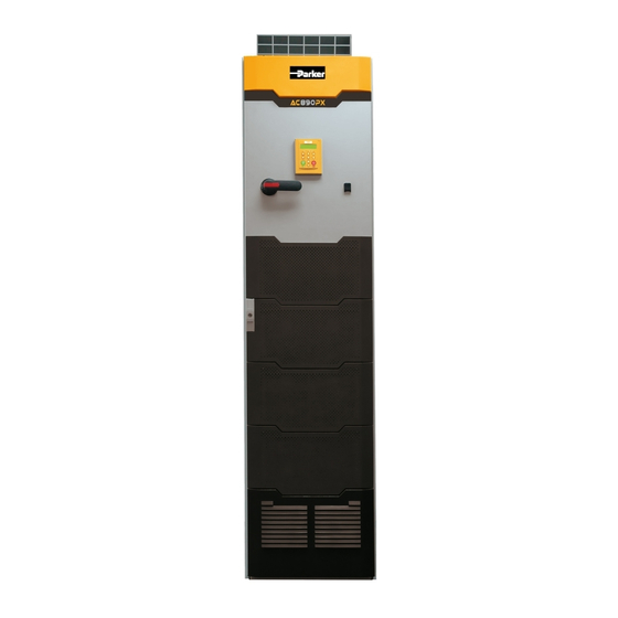
Page 6: Overview
Overview AC890PX (top wire entry) Page 6... -
Page 7: Ac890Px (Bottom Wire Entry)
AC890PX (bottom wire entry) Page 7... -
Page 8: Installation
For European installations and countries with EMC legislation refer to the 890 Engineering Reference Manual, Appendix C. Mounting Dimensions With any tall unit such as the AC890PX drive, it is advisable to secure the top to prevent it tipping over. OUTLET AIR During operation it must stand vertically on a solid, flat, horizontal, normally cool, non-flammable surface. -
Page 9: Ac890Px Power Connections
AC890PX Power Connections Components : Top Wire Entry Isolator Control Module/Control Terminals Auxiliary Transformer Set the transformer taps - see page 13. Motor/Output Connections Protective Earth/Ground Internal Brake Resistor Thermal Overload Protection User Blower Motor Thermal Overload Protection Auxiliary Supply Protection -... -
Page 10: Wiring Diagram : Top Wire Entry
Wiring Diagram : Top Wire Entry Permanent Earthing Each unit must be permanently earthed according to EN 61800-5. For permanent earthing, EN 61800-5 states that: A cross-section conductor of at least 10mm² copper or 16mm aluminium is required. Conductors must be sized in accordance with Local Wiring Regulations which always take precedence. -
Page 11: Components : Bottom Wire Entry
Components : Bottom Wire Entry Isolator Control Module/Control Terminals Auxiliary Transformer Set the transformer taps - see page 13. Motor/Output Connections Protective Earth/Ground Internal Brake Resistor Thermal Overload Protection User Blower Motor Thermal Overload Protection Auxiliary Supply Protection - Circuit Breaker (primary) Auxiliary Supply Protection - Semiconductor Fuse (secondary) -
Page 12: Wiring Diagram : Bottom Wire Entry
Wiring Diagram : Bottom Wire Entry Page 12... -
Page 13: Auxiliary Transformer Taps (C)
Auxiliary Transformer Taps (C) The transformer is tapped for no Auxiliary Transformer 40A Semi-Conductor Fuse connection, i.e. 0V - PARK when it leaves the factory and the drive will not operate. Either a low voltage or high voltage transformer option is fitted to the drive. -
Page 14: Ac890Px Control Connections
AC890PX Control Connections Speed Reference Sequencing Analog • Connect volt-free • Connect a 10kΩ potentiometer at • SPEED FEEDBACK contacts as required terminal block X12 (Analog I/P 3) 10V = ±100% speed • RUN (maintained contact) at terminal X12/0 6... -
Page 15: Ac890Px Feedback Connections
CLOSED-LOOP VEC mode, as the encoder direction must be correct for this mode to operate. Using other types of encoders requires the 890 DSE Configuration Tool and the setting of other parameters. Refer to the AC890PX Engineering Reference Manual for details of these parameters. OPTION F... -
Page 16: Drive Start-Up
Drive Start-up Before Applying Power : • Read the Safety section at the front of the QuickStart. • Ensure that all local electric codes are met. • Check for damage to equipment. • Check for loose ends, clippings, filings, drilling swarf etc. lodged in the drive and system. -
Page 17: Quick Setup Parameters
Quick Setup Parameters The following is a list of the Quick Setup parameters you must check before starting the drive. Set only the ones marked with “x” in the table below, under the intended mode of operation. V/Hz Vector PMAC Control Mode Select the intended operating mode Max Speed... -
Page 18: Autotune
Autotune This section is only for operating in Sensorless or Closed-loop Vector modes. If the drive is in V/Hz mode, Autotune is unnecessary and will not Enable. • Ensure that MAX SPEED is greater than NAMEPLATE RPM for a successful autotune. •... -
Page 19: Running In Local
Setup to desired level. If the drive trips on Overvoltage, extend the RAMP DECEL TIME or connect a braking resistor. Refer to the AC890PX Engineering Reference Manual. Go to SYSTEM::SAVE CONFIG::APPLICATION and UP arrow to save your settings Values are stored during power-down. -
Page 20: Appendix A: Using The 6901 Keypad
Appendix A: Using the 6901 Keypad The 6901 keypad has a two-line backlit LCD display with units and symbols. It can be used to setup and configure the AC890PX in plain language. It can also be used to operate the drive in Local mode from its Start and Stop buttons, Jog and reverse. -
Page 21: The Menu Structure
DOWN arrow to get to the SYSTEM menu menu at level 1 NOTE Refer to the AC890PX Engineering Reference Manual for a list of available parameters. To change Operating Mode: From power-up, the keypad displays the Software Version, and then times-out to show the Remote Setpoint. -
Page 22: Appendix B: Analog And Digital I/O
Appendix B: Analog and Digital I/O The terminal function names apply to the factory shipping configuration. These terminals may have different functions if the configuration has been modified using DSE. Page 22... - Page 23 Page 23...
-
Page 24: Appendix C: Electrical Ratings
Appendix C: Electrical Ratings Page 24... - Page 25 Page 25...
- Page 26 Page 26...
Need help?
Do you have a question about the AC890PX and is the answer not in the manual?
Questions and answers