Table of Contents
Advertisement
Quick Links
Download this manual
See also:
Installation Manual
Advertisement
Table of Contents
Troubleshooting

Related Manuals for Parker ACR9000


Summary of Contents for Parker ACR9000
-
Page 2: User Information
ACR series products and the information in this guide are the proprietary property of Parker Hannifin Corporation or its licensers, and may not be copied, disclosed, or used for any purpose not expressly authorized by the owner thereof. -
Page 3: Table Of Contents
Chapter 1 Introduction ........................1 ACR9000 Controllers—Overview....................2 Checking Your Shipment......................2 Controller Options ........................2 Accessories ..........................3 Compatible Parker Hannifin Products ..................4 About This Guide........................4 Assumptions of Technical Experience ..................5 Technical Support ........................5 Chapter 2 Specifications....................... 6 Environmental Specifications ..................... - Page 4 Appendix C Regulatory Compliance–UL, EMC, and CE............89 System Installation Overview ....................90 General Safety Considerations....................90 General EMC Considerations ....................90 Installing the ACR9000 Controller ..................91 Regulatory Agencies ........................ 99 Standards of Compliance ......................99 Index ............................100...
-
Page 5: Table Of Tables
Table of Tables Table 1 Ship Kit for ACR9000 Stand-Alone Controller .............. 2 Table 2 ACR9000 Controller Accessories.................. 4 Table 3 Controller Cooling Requirements .................. 7 Table 4 Controller Weight......................8 Table 5 Controller Dimensions ....................8 Table 6 ACR9000 Power Requirements .................. 10 Table 7 Controller I/O Interface Configurations................ - Page 6 Figure 1 ACR9000 2/4 Axis Dimensions..................9 Figure 2 ACR9000 6/8 Axis Dimensions..................9 Figure 3 ACR9000 Stand-Alone Controller 2/4 Axis Front Panel Interfaces ......13 Figure 4 ACR9000 Stand-Alone Controller 6/8 Axis Front Panel Interfaces ......14 Figure 5 Equivalent Circuit for Axis Power Source ..............18 Figure 6 Equivalent Circuit for Drive Step and Drive Direction Outputs........
- Page 7 Product Type....ACR9000 Controller The above product complies with the requirements of directives: • EMC Directive 89/336/EEC • Low Voltage Directive 73/23/EEC • CE Marking Directive 93/68/EEC. Provided the installation requirements described in this guide are met, and there are no special requirements of the installation and operating environment so that the application may be considered typical.
- Page 8 Warning! Risk of damage and/or personal injury The ACR9000 controllers described in this guide contain no user-serviceable parts. Attempting to open the case of any unit, or to replace any internal component, may result in damage to the unit and/or personal injury. This may also void the warranty.
-
Page 9: Important User Information
The information in this user guide, including any apparatus, methods, techniques, and concepts described herein, are the proprietary property of Parker Hannifin or its licensors, and may not be copied disclosed, or used for any purpose not expressly authorized by the owner thereof. -
Page 10: Change Summary
Change Summary Revision D Changes This document, 88-022337-01D, supersedes 88-022337-1C. Changes associated with ACR9000 User Guide revisions, and document clarifications and corrections are as follows: Topic Description Battery Backup Added specifications for Battery Backup option. See Battery Backup. Aries Cable... - Page 11 This page is intentionally blank. - xi -...
-
Page 13: Chapter 1 Introduction
IN THIS CHAPTER • ACR9000 Controllers—Overview............2 • Checking Your Shipment ..............2 • Controller Options ................. 2 • Accessories ................... 3 • Compatible Parker Hannifin Products........... 4 • Assumptions of Technical Experience ..........5 • Technical Support ................. 5... -
Page 14: Acr9000 Controllers-Overview
Checking Your Shipment Confirm that you have received all items in Table 1. These items ship with the ACR9000 controller. If you are missing an item, call the factory. For contact information, see “Technical Assistance” on the inside cover, page... -
Page 15: Accessories
Accessories ACR9000 Controller Accessories Description Part Number Drive Cables Aries drive cable 71-021599-xx Compax3 drive cable 71-021108-xx Dynaserv G2 drive cable 71-021107-xx Flying leads cable 71-022344-xx Gemini Servo drive cable 71-021112-xx Gemini Stepper drive cable 71-022316-xx Parker Stepper drive cable 71-021113-xx (E-AC, E-DC, Zeta, etc.) -
Page 16: Compatible Parker Hannifin Products
For information about cables, see Chapter 3 Installation, beginning on page 40. About This Guide This purpose of this guide is to help you install the ACR9000 Stand-Alone Controller for use with a variety of Parker Hannifin drives. The ACR9000 controller comes in two models of housing, distinguished primarily by their width, and each model supports two configurations of I/O interfaces. -
Page 17: Assumptions Of Technical Experience
Assumptions of Technical Experience To install and troubleshoot the ACR9000 Stand-Alone Controller, you should have a fundamental understanding of the following: • Electronic concepts such as voltage, current, and switches. • Mechanical motion control concepts such as inertia, torque, velocity, distance, and force. -
Page 18: Chapter 2 Specifications
C H A P T E R T W O Specifications Chapter 2 Specifications IN THIS CHAPTER • Environmental Specifications ..............7 • Mechanical Specifications..............8 • Electrical Specifications ..............10 • External I/O Interface Connectors............12... -
Page 19: Environmental Specifications
Environmental Specifications The controller operates in an ambient temperature range of 0 ° C (32 ° F) to 50 ° C (122 ° F). The unit can tolerate atmospheric pollution degree 2: only dry, non-conductive pollution is acceptable. Therefore, we recommend that you mount the controller in a suitable enclosure as described in “Installation Safety Requirements”... -
Page 20: Mechanical Specifications
Mechanical Specifications The ACR9000 Stand-Alone Controller housing is a vented, metal enclosure. There are two models of controller housing, distinguished primarily by their width. In this guide, the models are identified by the number of Axis I/O interfaces that they provide—the 2/4 Axis Configuration and the 6/8 Axis Configuration. -
Page 21: Figure 1 Acr9000 2/4 Axis Dimensions
Figure 1 ACR9000 2/4 Axis Dimensions Figure 2 ACR9000 6/8 Axis Dimensions Chapter 2 Specifications - 9 -... -
Page 22: Electrical Specifications
Connector Specification— AC Power Mating Parker Hannifin cables are available with mating connectors attached for 120 VAC installations (Parker Hannifin P/N: 44-000054-01 supplied with product). 120/240 VAC mating connectors are not provided with the ACR9000 Stand- Alone Controller. Manufacturer ........... Schurter or equivalent (www.schurterinc.com) -
Page 23: Ac Power Fuse
AC Power Fuse The controller has one accessible fuse located by the AC power connector. For the ACR9000 to maintain UL Recognition, you must use one of the approved vendor part numbers listed below. AC Power Fuse Requirements Voltage Rating......... 250 VAC Current Rating......... -
Page 24: External I/O Interface Connectors
0 or 1 0 or 1 0 or 1 1. This interface is an option on the ACR9000 controller. For more information, Controller Options on page 2 Table 7 Controller I/O Interface Configurations On all configurations of the controller, the I/O interface connectors are on the front panel. -
Page 25: Figure 3 Acr9000 Stand-Alone Controller 2/4 Axis Front Panel Interfaces
CANopen Status LED Axis Connectors GP Inputs and Outputs Connectors COM1 Connector Enable Connector AC Power Status LED AC Power Fuse AC Power Connector Figure 3 ACR9000 Stand-Alone Controller 2/4 Axis Front Panel Interfaces Chapter 2 Specifications - 13 -... -
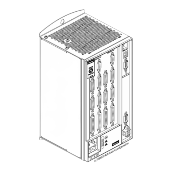
Page 26: Figure 4 Acr9000 Stand-Alone Controller 6/8 Axis Front Panel Interfaces
Figure 4 ACR9000 Stand-Alone Controller 6/8 Axis Front Panel Interfaces - 14 - ACR9000 Hardware Installation Guide... -
Page 27: Axis Connectors, 0-7
• Electrical/Timing characteristics • Internal circuit schematics Axis Connectors, 0-7 The ACR9000 controller employs a single connector that handles both the encoder and drive signals—the Axis connector. Therefore, each axis of motion has its own integrated encoder/drive connector. This section contains connector specifications, a connector pinout, and information about the drive and encoder functions of the Axis connectors. -
Page 28: Axis Connector Pinout, Axis 0−3
Note: If the Enable Drive I/O flag is set, then the AcroBasic direct I/O commands can only report the output status and cannot set or clear the output state. The ACR9000 controller ships with a default state for all axes— Enable Drive I/O flag set. -
Page 29: Axis Connector Pinout, Axis 4−7
Note: If the Enable Drive I/O flag is set, then the AcroBASIC direct I/O commands can only report the output status and not set or clear the output state. The ACR9000 controller ships with a default state for all axes of— Enable Drive I/O flag set. -
Page 30: Axis Connector Power Source
The power source typically is used to power: • An external encoder • Optical inputs and/or outputs between the ACR9000 and an external drive Table 10 contains the electrical characteristics for the Axis-Connector power source. Figure 1 provides a schematic of its circuit. -
Page 31: Drive Function
Drive Function This section describes the drive function of the Axis interface, as well as an AcroBASIC command reference, signal assignments, electrical/timing characteristics, and internal circuit schematics. Modes of Operation The Drive Step and Drive Direction output feature of the drive interface has two modes of operation: •... -
Page 32: Table 12 Drive Commands
Drive Step and Enable Drive I/O ACR9000 and an external stepper drive amplifier, Drive Direction such as the E-AC series from Parker. For more flag, ATTACH Output +/− information, see “Modes of Operation” on page The Drive AOUT output provides the analog +/−... -
Page 33: Table 13 Outputs-Drive Step And Drive Direction Electrical/Timing Characteristics
Drive Electrical/Timing Characteristics Table 13 through Table 16, on pages 21 and 22, contain the electrical timing/characteristics for the following drive functions: • Outputs—Drive Step and Drive Direction • Outputs—Drive AOUT • Inputs—Drive Fault • Outputs—Drive Enable and Drive Reset Important! These electrical/timing characteristics only apply to the Axis connectors. -
Page 34: Table 15 Inputs-Drive Fault Electrical/Timing Characteristics
Load current, I (35 °C < T ≤ 50 °C) — — Short-circuit trip current — — Note: All parameters are at the connector pin. Table 16 Outputs—Drive Enable and Drive Reset Electrical/Timing Characteristics - 22 - ACR9000 Hardware Installation Guide... -
Page 35: Figure 6 Equivalent Circuit For Drive Step And Drive Direction Outputs
Drive Internal Circuit Schematics Figure 6 through Figure 10 show the internal circuit for the following drive functions: • Outputs—Drive Step and Drive Direction • Outputs—Drive AOUT • Inputs—Drive Fault • Outputs—Drive Enable and Drive Reset • Drive Talk Signals Outputs—Drive Step and Drive Direction Figure 6 Equivalent Circuit for Drive Step and Drive Direction Outputs Drive AOUT Outputs... -
Page 36: Figure 8 Equivalent Circuit For Drive Fault Inputs
Drive Enable and Drive Reset Outputs Figure 9 Equivalent Circuit for Drive Enable and Drive Reset Outputs Drive Talk Drive Talk signals are reserved for compatibility with Parker Hannifin drives and are not available for general use. Figure 10 illustrates the Drive Talk signal path. -
Page 37: Encoder Function
Encoder Function This section describes the encoder function of the Axis interface, as well as signal assignments, electrical/timing characteristics, and internal circuit schematics. Modes of Operation The encoder feature has four modes of operation: • Quadrature • Step and Direction •... -
Page 38: Table 17 Encoder Signal Assignments And Supported Features
Duty cycle (pre-quad frequency ≤ 2.5 MHz) Duty cycle (pre-quad frequency > 2.5 MHz) −200 Receiver Differential Threshold, V +200 Common mode range, V −10 13.2 Note: All parameters are at the connector pin. Table 18 Encoder Electrical/Timing Characteristics - 26 - ACR9000 Hardware Installation Guide... -
Page 39: Auxiliary Encoder Connector
Encoder Circuit Schematic Figure 11. Equivalent Circuit for Encoder Auxiliary Encoder Connector The 2/4 Axis Configuration of the ACR9000 controller provides one Auxiliary Encoder connector, labeled E 8. The 6/8 Axis Configuration provides NCODER two, which are labeled E 8 and E 9. -
Page 40: General Purpose Inputs/Outputs
Connector Type........25-pin D-sub, 2-row (female socket) Manufacturer Part Number ..... K42-B25S/S-A4NR General Purpose Inputs/Outputs Mating-Connector Specification Parker Hannifin does not provide mating connectors with the ACR9000 Stand-Alone Controller. However, you can order Parker Hannifin cables with mating connectors attached. Manufacturer ........... AMP or equivalent (www.amp.com) Connector Type........ -
Page 41: Table 20 Gp Input/Output Connector Pinout (2/4/6/8 Axis Configuration)
General Purpose Inputs/Outputs Connector Pinouts Table 20 contains the General Purpose (GP) Inputs/Outputs and Trigger Inputs connector pinouts for the 2/4 Axis Configuration controller. Table 21 on page 30 contains the pinout for the additional GP Inputs/Outputs connectors on the 6/8 Axis Configuration. Use only Trigger Inputs 24 through 31 to capture position on A 0 through 3, and E... -
Page 42: Table 21 Gp Input/Output Connector Pinout (6/8 Axis Configuration)
Output 39− Input 23+ Output 39+ Note: Input 17 and Trigger Input 77 are paired on pins 13 and 25 to ease cable assembly. Table 21 GP Input/Output Connector Pinout (6/8 Axis Configuration) - 30 - ACR9000 Hardware Installation Guide... -
Page 43: Table 22 Gp Inputs 0−11 & 12−23 Connector Electrical/Timing Characteristics
GP Trigger Input/Output Electrical/Timing Characteristics GP Inputs 0−11, 12−23 Description Units Turn-on time Turn-off time Guaranteed on voltage Guaranteed off voltage Maximum forward voltage Maximum reverse voltage −30 Forward current Note: All parameters are at the connector pin. − − Table 22 GP Inputs 0 11 &... -
Page 44: Table 24 Gp Outputs 32−39 Connector Electrical/Timing Characteristics
GP Input/Output Connector Circuit Schematics This section contains schematics of the input and output circuits of the ACR9000 controller. All inputs have the same circuit schematic and all outputs have the same circuit schematic. Figure 12 Equivalent Circuit for GP Inputs/Trigger Inputs Connector... -
Page 45: Enable Connector
Figure 13 Equivalent Circuit for Outputs Enable Connector When you de-assert the Enable input, an immediate kill of all motion without de-acceleration occurs. The functionality of the controller requires that current must flow through the Enable input for motion to occur on an axis. If current flow does not assert the input, motion does not occur when you command it, and the error message “Motion Enable Input Open”... -
Page 46: Table 25 Enable Connector Pinout
Enable Mating-Connector Specification An Enable mating connector ships with the ACR9000 Stand-Alone Controller Manufacturer ........... Amphenol PCD or equivalent (www.amphenol.com) Connector Type........2-pin, removable (female socket) Manufacturer Part Number ..... ELFP02210E Parker Hannifin Part Number....43-021606-01 Pitch ............0.200 in (5.03 mm) Wire range.......... -
Page 47: Com1 Connector
Enable Circuit Schematic Figure 14 Equivalent Circuit for Enable Connector COM1 Connector The COM 1 port on the ACR9000 controller supports the following transmission characteristics: • 1200, 2400, 4800, 9600, 19200, 38400 baud (The controller automatically detects baud upon start-up.) •... -
Page 48: Canopen Connector
COM1 Mating-Connector Specification Mating connectors are not provided with the ACR9000 Stand-Alone Controller. Parker Hannifin cables are available with mating connectors attached. Manufacturer ........... AMP or equivalent (www.amp.com) Connector Type........9-pin, D-sub, 2-row (female socket) Connector Kit .......... AMP Part Number 747951-1... -
Page 49: Table 28 Canopen Connector Pinout
CANopen Mating-Connector Specification The ACR9000 Stand-Alone Controller does not ship with a mating connector. However, you may order a Parker Hannifin cable with a mating connector attached. Manufacturer ........... AMP or equivalent (www.amp.com) Connector Type........9-pin, D-sub, 2-row (female socket) Connector Kit .......... -
Page 50: Figure 15 Equivalent Circuit For Canopen
For the latest information on supported CANopen features, see our website, www.parkermotion.com. Note: The ACR9000 does not support multi-master networks. There can be only one master, an ACR9000 controller. For information on connecting the controller to a CANopen network, see “CANopen Connection” on pages 62 through 67. -
Page 51: Ethernet Connector
Ethernet Connector The ACR9000 controller implements the Ethernet network interface with the following features: • 10/100 Mbps (self-configuring), full-duplex capable connection • TCP/IP version 4 • UDP protocols Ethernet Connector Pinout Table 29 contains the Ethernet connector pinout: Signal Wire Color... -
Page 52: Chapter 3 Installation
C H A P T E R T H R E E Installation Chapter 3 Installation IN THIS CHAPTER • Before You Begin ................41 • Installation Safety Requirements ............41 • Installation Overview ................42 • Mounting Guidelines ................43 •... -
Page 53: Before You Begin
Before You Begin Warning! The ACR9000 Stand-Alone Controller connects to your system’s other mechanical and electrical components. Be sure to test your system for safety under all potential conditions. Failure to do so may result in damage to equipment and serious injury to personnel. -
Page 54: Installation Overview
3. If you require RS-485 operation, configure the COM1 port connecting cable as specified in “COM1 Connection” on page 48. 4. Mount the ACR9000 controller following the guidelines on page 43. 5. Connect all cables and electrical components, except the AC power cord. -
Page 55: Mounting Guidelines
Mounting Guidelines Mount the ACR9000 Stand-Alone Controller before making any electrical connections or applying power. The figures on the following pages illustrate mounting specifications for the 2/4 Axis Configuration and the 6/8 Axis Configuration of the controller. Figure 17 and Figure 18 on pages 44 and 45 provide the measurements. -
Page 56: Figure 17 Mounting Specifications For 2/4 Axis Configuration
Figure 17 Mounting Specifications for 2/4 Axis Configuration - 44 - ACR9000 Hardware Installation Guide... -
Page 57: Figure 18 Mounting Specifications For 6/8 Axis Configuration
Figure 18 Mounting Specifications for 6/8 Axis Configuration Chapter 3 Installation - 45 -... -
Page 58: Figure 19 Mounting Clearance For 2/4 Axis Configuration
Figure 19 Mounting Clearance for 2/4 Axis Configuration - 46 - ACR9000 Hardware Installation Guide... -
Page 59: Figure 20 Mounting Clearance For 6/8 Axis Configuration
Figure 20 Mounting Clearance for 6/8 Axis Configuration Chapter 3 Installation - 47 -... -
Page 60: Cable Installation
Cable Installation All connectors are on the front panel of the ACR9000 controller. You may install cables in any order; however, make sure to install the power cord last . For convenience, we recommend starting with the connections at the bottom of the front panel. -
Page 61: Table 31 Com1 Transmission Modes
Note: Do not connect the ACR9000 controller in an RS-232 or RS-485 daisy chain or multi-drop network; it will not function properly. The COM1 port is hardware configurable for either an RS-232 or RS-485 full-duplex operation. (It does not support half-duplex operation.) Use the information in this section to configure your cable and connectors for RS-232 or RS-485 operation. -
Page 62: Table 32 Com1 Rs-232 Pinout
RS-232 Communications The controller’s COM1 port default configuration is for RS-232 transmission with a standard cable. For information on cables available from Parker Hannifin, see Table 2 ACR9000 Controller Accessories on page 4. Before installing a cable, verify that the pin connections between the PC and the controller are configured as shown in Table 32. -
Page 63: General Purpose Input/Output Connection
I/O Interface,” pages 28 through 32 for specifications, illustration, and labeling of the connectors.) To aid installation, Parker Hannifin offers the VM25 expansion I/O module to adapt the controller’s 25-pin D-sub connector(s) to screw terminals. For more information, see Appendix B VM25 Module on page 87. -
Page 64: Axis Connection
Axis Connection Your ACR9000 controller may be configured with two, four, six, or eight Axis connectors depending on your requirements. Each connector functions as an integrated drive/encoder interface for one axis of motion. Make one connection for each required axis of motion. The connectors are on the front panel of the unit and are 26-pin, female D-sub, high-density connectors. -
Page 65: Table 35 Connection To Aries Pinout
Aries Drives The following pinout is for the Aries drive’s 26-pin Drive I/O connector . Part number ............71-021599-xx Note: A box surrounding pins indicates a requirement for twisted-pair wiring. ACR9000 Controller Aries Wire Color Signal 5 VDC PWR Black... -
Page 66: Table 36 Connection To Compax3 Pinout
Drive GND Violet — NOTE: In the controller connector, pins 17 & 19 are jumpered. In the Compax3 X12 connector, pins 1, 7, & 11 are jumpered. Table 36 Connection to Compax3 Pinout - 54 - ACR9000 Hardware Installation Guide... -
Page 67: Table 37 Connection To Dynaserv Pinout
Dynaserv G2 Drives The following pinout is for the Dynaserv drive’s CN4 connector. Part number ............71-021107-xx Note : A box surrounding pins indicates a requirement for twisted-pair wiring. ACR9000 Controller Dynaserv Wire Color Signal 5 VDC PWR Wht-Blu Encoder CHA+ Black Encoder CHA−... -
Page 68: Table 38 Connection To Gemini Servo Pinout
Brown Drive Fault− Drive Enable− Gray Drive Enable+ Blu-Wht Wht-Blu Drive Reset− Drive Reset+ Orange Note: In the controller connector, pins 16 & 18 are jumpered. Table 38 Connection to Gemini Servo Pinout - 56 - ACR9000 Hardware Installation Guide... -
Page 69: Table 39 Connection To Gemini Stepper Pinout
Gemini Stepper Drives The following pinout is for the Gemini Stepper drive’s 50-pin Drive I/O connector. Part number ............71-022316-xx Note : A box surrounding pins indicates a requirement for twisted-pair wiring. ACR9000 Controller Stepper Wire Color Signal DC RETURN Pink... -
Page 70: Table 40 Connection To Parker Stepper Pinout
Parker Stepper Drives: E-AC, E-DC, Zeta, etc. The following pinout is for all Parker Stepper drive Indexer connectors. Part number ............71-021113-xx Note : A box surrounding pins indicates a requirement for twisted-pair wiring. ACR9000 Controller Stepper Wire Color Signal... -
Page 71: Table 41 Connection To Slvd And Hpd Pinout
The following pinout is for the SVLD drive’s X3 connector, and the HPD drive’s X7 connector. Part number ............71-021109-xx Note : A box surrounding pins indicates a requirement for twisted-pair wiring. ACR9000 Controller SLVD & HPD Wire Color Signal DC RETURN... -
Page 72: Table 42 Connection To Vix Pinout
Drive AOUT+ Blue Violet Drive AOUT− DRV FAULT IN– Gray DRV ENABLE+ Brown Note: In the controller connector, pins 9 & 16, and 20 & 24 are jumpered. Table 42 Connection to ViX Pinout - 60 - ACR9000 Hardware Installation Guide... -
Page 73: Table 43 Connection To Drive With Flying Leads
Other Drives The following pinout is for connection to a drive with a flying leads assembly. Part number ............71-022344-xx Note : A box surrounding pins indicates a requirement for twisted-pair wiring. [ACR9000 Controller Other Wire Color Signal 5 VDC PWR... -
Page 74: Canopen Connection
This section contains guidelines and cable specifications for connecting a CANopen network with multiple slave nodes or a single slave node to the ACR9000 master node. The CANopen connector is on the front panel of the controller. (For specifications, see “CANopen Connector” on page 36.) Use the following guidelines for installing a CANopen network with the ACR9000 controller. -
Page 75: Table 44 Canopen Pinout (Minimum)
Figure 23 CANopen Network ACR9000 CANopen Pinout (Minimum) Description Wire Color Connect to CAN_L on slave node(s) Blue Connect to CAN_H on slave node(s) White Connect to CAN_GND on slave node(s) Black Notes • CANopen recommends that all nine wires on the connector be routed to support future network enhancements. -
Page 76: Table 45 Canopen Point-To-Point Cable
ISO 11898. For point-to-point connection between a single CANopen slave node and the ACR9000 master node, Parker Hannifin provides the cable assembly in Table 45. Table 46 contains the cable’s connector pinout. CANopen Point-To-Point Cable... -
Page 77: Table 47 Canopen Cables For Multiple-Node Networks
Maximum cumulative drop length is the total length of all drop lines. Keep wires as short as possible, especially drop lines. Parker Hannifin recommends installing a termination resistor (120Ω) at both ends of the CANopen trunk line. System noise, improper cable routing, incorrect cable type, and number of CANopen nodes can all degrade network performance. -
Page 78: Table 49 Canopen Bus-Cable Specifications
For proper shielding requirements, see Appendix C Regulatory Compliance–UL, EMC, and CE on page 89. For more information on selecting cables, see the CANopen spec DR303 – “CANopen Cabling and Connector Pin Assignment”, www.canopen.org/canopen. Table 49 CANopen Bus-Cable Specifications - 66 - ACR9000 Hardware Installation Guide... -
Page 79: Table 50 Canopen Network Installation Test
Having performed the electrical installation test, you can proceed with a functional test. Single Node Network 1. Power up the ACR9000. The controller should have a green, blinking CANopen Status LED, and the I/O node should have a green blinking Run LED. - Page 80 Next, the hardware addresses are assigned. The first node requires no configuration—the factory default hardware ID is set to 1, and the ACR9000 is factory configured to recognize hardware ID 1. The hardware of the second and third nodes are configured, then the following parameters are set:...
-
Page 81: Ethernet Cable Specification
Cable............RJ-45 Ethernet, unshielded CAT 5E Ethernet Connection The Ethernet port is located on the front panel of the ACR9000. This is an optional feature. (For specifications, see Ethernet Connector on page 39.) Before connecting to an Ethernet port, you must configure the ACR9000 to use an IP address and subnet mask that is valid for your network. -
Page 82: Usb Cable Specification
Note: Parker Hannifin does not provide USB cables. Windows 98SE, Windows 2000 or Windows XP To connect the ACR9000 USB port to Windows 98SE, 2000, or XP follow these steps: 1. Connect the ACR9000 to your PC using a standard USB cable. -
Page 83: Auxiliary Encoder Connection
For information on single-ended encoders, see page 62. AC Power Connection After securely installing all other cables on the ACR9000 controller, connect the device to an external 120/240 VAC mains power source. For information on power requirements and the AC power connector, see “AC Power Supply Connector”... -
Page 84: Chapter 4 Troubleshooting
C H A P T E R F O U R Troubleshooting Chapter 4 Troubleshooting IN THIS CHAPTER • Troubleshooting Guidelines ..............73 • LED Status Indicators ................. 74 • CANopen Connection ................. 76 • Ethernet Connection ................76 • RS-232/RS-485 Communication Problems ........76 •... -
Page 85: Troubleshooting Guidelines
Alternating Red/Green Contact Parker Hannifin Technical Assistance. 1. For Parker Hannifin Technical Assistance contact information, see page ii (inside front cover). Table 51 AC-Power-Status LED General Troubleshooting Use the following list as a guideline for troubleshooting. -
Page 86: Led Status Indicators
At least one of the error counters of the CAN Warning Limit Single flash controller has reached or exceeded the Reached warning level (too many error frames). Autobaud detection is in progress or LSS Flickering Autobaud/LSS services are in progress. - 74 - ACR9000 Hardware Installation Guide... -
Page 87: Ethernet Status Leds
Bus Off The CAN controller is bus off. Reset The ACR9000 is executing a reset. 1. LED Intervals: Flickering = on for ~50 ms and off for ~50 ms Blinking = on for ~200 ms and off for ~200 ms... -
Page 88: Canopen Connection
Do not proceed until the status LED indicates an Ethernet Link has been established. 4. Verify a valid IP and subnet mask has been assigned to the ACR9000. See Ethernet Cable Specification on page 69. 5. Test the IP and subnet assignment. At a DOS or command prompt type ping xxx.xxx.xxx.xxx where xxx.xxx.xxx.xxx represents the IP... -
Page 89: Rs-232/Rs-485 Communication Problems
RS-232/RS-485 Communication Problems If you cannot establish serial communication with the ACR9000 controller, use the information and procedures in this section to help isolate and resolve problems. For more information, see “COM1 Connector” on pages 35 and 36 and “COM1 Connection” on pages 48 through 51. -
Page 90: Table 57 Communications Port Error Messages And Resolutions
Testing the COM Port Test COM1 port communications using the ACR-View. 1. Cycle power on the ACR9000; this puts the controller in Autobaud. 2. On the ACR-View Project Tree : 1. Select the ACR9000 Controller. 2. Under the Communications box, select Serial . -
Page 91: Feedback Device Problems
If the feedback position does not change correctly, check the following: • Confirm that the feedback cables are wired correctly. • If the ACR9000 +5 VDC powers the feedback device, verify that the device is designed to be powered from +5 VDC and meets the current rating in Table 10 Axis Power Electrical Characteristics, on page 18. -
Page 92: Motion-Related Error Messages
• The load is jammed; remove power and clear jam. • Use the information in the section “Axis Status LED” on page 74 to determine LED states and methods of resolution. • See “General Drive I/O” below for drive-function specifics. - 80 - ACR9000 Hardware Installation Guide... -
Page 93: General Drive I/O
General Drive I/O For problems with the drive function of the Axis I/O, check the following configurations. 1. If the drive will not enable, verify that the drive’s fault output configuration is correct (Gemini command, OUTLVLx1 , etc.). See also AcroBASIC flag, Enable Drive I/O. -
Page 94: Stepper Axes
Direction − connection between the controller and the drive. For CW and CCW mode, switch the CW and CCW signal pairs between the controller and the drive. Swap the A+ and A − connections between the drive and the motor. - 82 - ACR9000 Hardware Installation Guide... - Page 95 2. If the stepper is unstable, follow these steps. Verify that you have attached the axis as a stepper and not as a servo. For more information, see the ATTACH command in the ACR User’s Guide (Online Help System in the ACR-View software).
-
Page 96: Appendix A Ssi Encoders
A P P E N D I X A SSI Encoders Appendix A SSI Encoders IN THIS CHAPTER • Overview ..................... 85 • Protocol ....................85 • Timing....................86... -
Page 97: Overview
SCLK. Master Device (ACR9000 Controller) The ACR9000 controller initiates a new SSI transfer at the beginning of a servo period by generating SCLK. The controller then qualifies subsequent data values on SDATA using the rising edge of SCLK. -
Page 98: Timing
Timing This section describes the SSI transfer cycle timing for the ACR9000 controller. Figure 24 illustrates the cycle timing and Table 59 contains the timing data. Figure 24 SSI Transfer-Cycle Timing SSI Transfer-Cycle Timing Data Symbol Description SCLK falling edge to first rising edge 0.5 x T3... -
Page 99: Appendix B Vm25 Module
A P P E N D I X B VM25 Module Appendix B VM25 Module IN THIS CHAPTER • VM25 I/O Expansion Module .............. 88... -
Page 100: Vm25 I/O Expansion Module
VM25 I/O Expansion Module The VM25 module provides screw-terminal connections for the General Purpose I/O connectors on the ACR9000 Stand-Alone Controller. The VM25 comes with a 2-foot cable (609.6 mm) that provides easy connection between the VM25 and the controller’s 25-pin I/O connectors. The VM25 expansion I/O module is ordered separately (part number “VM25”). -
Page 101: Appendix C Regulatory Compliance-Ul, Emc, And Ce
• System Installation Overview .............. 90 • General Safety Considerations ............90 • General EMC Considerations ............. 90 • Installing the ACR9000 Controller............91 • Regulatory Agencies ................99 • Standards of Compliance..............99 Appendix B VM25 - 89 -... -
Page 102: System Installation Overview
General EMC Considerations The ACR9000 product is a Motion Control Component and as such will be built in to another machine that will in turn be required to comply with the relevant directives of the marketplace. -
Page 103: Installing The Acr9000 Controller
In certain circumstances, opening the cover may void the product warranty. The ACR9000 controller is a vented product. To prevent material spilling into the controller, mount it under an overhang or in a suitable enclosure. ACR9000 products are made available under “Restricted Distribution” for use in the “Second Environment”... -
Page 104: Figure 26 360° Bonding Techniques
Controller’s inherent noise immunity, the following recommendations should be followed. • For EMC compliance, the ACR9000 controller must be installed within an earth-bonded metallic enclosure. The enclosure must provide at least 10 dB of shielding effectiveness for a Class A (industrial) installation. - Page 105 Again, the machine builder’s primary focus should be on ensuring operators are kept safe from all hazards. • Install a Mains filter. Installing with multiple ACR9000 controllers requires an EMC mains supply filter to meet EMC emission requirements. It is recommended that the controllers are mounted on a conductive panel which is shared with the EMC filters.
-
Page 106: Table 60 Mains Filter Selection
The design of the ACR9000 controller D-sub connectors provides a reliable earth bond when used with Parker EMC cabling. It requires no additional cable screen earth bond if the chassis of the ACR9000 is adequately bonded to the system earth. -
Page 107: Table 61 Enclosure Mounting Clamps
Some installations may require that you take additional EMC measures. To further increase product immunity and reduce product emissions, you may add clip-on ferrite absorbers to all cables. Parker Hannifin recommends ferrites with at least 200 ohm impedance at 100 MHz,... -
Page 108: Figure 27 Typical Lvd/Emc Installation
Panel Installation in an Earth-Bonded Metallic Enclosure Figure 27 Typical LVD/EMC Installation Warning! These products have been developed for industrial environments. Due to exposed high voltage terminals, these products must not be accessible to users while under normal operation. - 96 - ACR9000 Hardware Installation Guide... -
Page 109: Figure 28 2/4 Axis Configuration Panel Layout Dimensions
Panel Layout Figure 28 2/4 Axis Configuration Panel Layout Dimensions Appendix B VM25 - 97 -... -
Page 110: Figure 29 6/8 Axis Configuration Panel Layout Dimensions
Figure 29 6/8 Axis Configuration Panel Layout Dimensions - 98 - ACR9000 Hardware Installation Guide... -
Page 111: Regulatory Agencies
Regulatory Agencies The ACR9000 family of products is designed to meet the requirements of global regulatory agencies. ACR9000 products have shown compliance with the regulatory agencies in the following list. The list also shows additional steps users must take to ensure compliance. -
Page 112: Index
......... 23 cooling requirements ......7, 43 drive enable ........24 cUL ............. 99 drive fault........24 CW and CCW mode, drive..... 19 drive reset........24 CW and CCW mode, encoder ....25 - 100 - ACR9000 Hardware Installation Guide... - Page 113 LED..........75 Gemini Servo ........56 troubleshooting........ 75 Gemini Stepper........ 57 European Conformance Statement ..vii Parker Stepper......... 58 ferrite absorbers ......95, 96 filters, mains ........93, 94 SLVD & HPD ........59 ViX..........60 flow control, COM1 port.....35, 50, 77 drive connector....
- Page 114 10 user enable interface ....enable fuse ..........11 varistors ........94, 96 battery backup ........ 11 VM25 I/O expansion module ....88 cooling ..........7 weight ........... 8 electrical ........10–38 - 102 - ACR9000 Hardware Installation Guide...
Need help?
Do you have a question about the ACR9000 and is the answer not in the manual?
Questions and answers