Advertisement
Quick Links
LUXOMAT
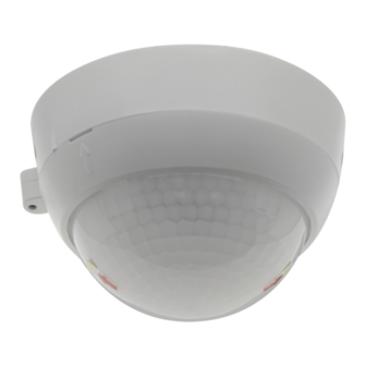
Installation and Operating Instruction for B.E.G. - Occupancy detector PD4-M-DALI/DSI-SM/FC
1. Product information
•
Occupancy detector for daylight-dependent lighting
control
•
DALI / DSI interface for controlling digitally dimmable
electronic ballasts as a group
•
Switching between DSI and DALI program by remote
control or DIP switch
•
Extension of the detection area by slave devices is
possible
•
Other functions adjustable by remote control (optional)
•
Manual switching and dimming via pushbutton possible
•
Orientation light function
2. Operation
The presence detector controls the light automatically according
to people present (movements) and the ambient brightness.
The integrated light sensor constantly measures the ambient light
and compares it with the set value brightness on the detector.
If the ambient light is sufficient, lighting will not be switched.
If the ambient light level is below the set value brightness, a
movement activates the lighting in the room.
The detector switches the light off despite of a person being pres-
ent if there is enough natural light for 5 min or if no movement is
detected for one follow-up time.
3. Safety information
Work on the 110-240 V mains supply may only
be carried out by qualified professionals or by
!
instructed persons under the direction and super-
vision of qualified skilled electrical personnel in
accordance with electrotechnical regulations.
Disconnect supply before installing!
This device is not suitable for disconnection.
Mounting the cover ring after introduction of the
power cable (FC version).
4. Mounting
In master/slave mode, the master device must always
!
be installed at the location with least daylight.
The light sensor must be positioned facing away from
!
the window.
4a. Mounting SM
The detector has to be mounted
on a plane and solid surface.
open
Before mounting, the lense has to be
close
removed. To do so, twist the lense
anticlockwise through approx. 5°
and lift off.
Having connected up the cables in
accordance with regulations, put on
the lense by turning in a clockwise
direction (see fig. 1). Apply mains
voltage.
Figure 1
4b. Mounting FC
68 mm
A circular opening of diameter
68 mm
68 mm must be produced in the
ceiling. Having connected up the
cables in accordance with regula-
tions, the detector is inserted into
the opening and fixed into
position with the assistance of the
spring clips (see figure 2).
Figure 2
®
PD4-M-DALI/DSI
5a. Position DIP switches, LEDs and
Potentiometers SM
Light measurement
C
B
1
A
2
DIP
PD4-Surface
3
mounting
5b. Position DIP switches, LEDs and
Potentiometer FC
I
PD4-
False ceiling
mounting
3
1
2
DIP
DIP switch functions
DIP 1
Full automatic mode
(VA)
DIP 2
LED ON
DIP 3
Operation mode DALI
Potentiometer A Brightness set value (constant light control)
Potentiometer B Follow-up time light
Potentiometer C Follow-up time (orientation light)
LED I
green
LED II red
LED III white
6. Self test cycle/Startup behavior
The product enters an initial 60-second self-test cycle, when the
supply is first connected. During this time the device does not
TIME
respond to movement and stays on.
18 16
10
6
22
3
25
1
30
TE
7. Putting into operation/Settings
Brightness set value for constant light control
LUX
2000
(Potentiometer A)
1200
600
The brightness set value can be defined between
200
TIME
10 and 2000 Lux. The potentiometer enables a free
40
18 16
selection of the brightness value.
10
6
22
3
25
1
Symbol :
Night-time operation
30
TE
Symbol
: Daytime operation
20%
(light evaluation inactive)
50 30
10
5
60
Follow-up time "Light" (Potentiometer B)
TIME
LUX
2000
The follow-up time can be set to 1 to 30 minutes.
1200
18 16
10
600
6
22
Symbol TE: test mode
200
3
25
1
40
30
Irrespective of the brightness, every movement switch-
TE
es the light on for 1sec., then off again for 2 sec.
9s
2s
LED ON
20%
Follow-up time orientation light (Potentiometer C)
LED OFF
Manually switching the orientation light on/off.
50 30
10
LUX
5
2000
60
"ON" for permanent orientation light
1200
600
"OFF" for switching off the orientation light
200
40
8. Wiring diagram
Schematic diagram - when connecting the detector, please respect
the labelling of the terminal connections at the detector!
Standard mode with Master/Slave device(s)
I II III
L
N
T1
II III
Connected Slave devices must have the same phase as the
!
Master device.
A
B
C
9. Manual switching and dimming (see section 23)
By pressing the push button, the phase can be given to the S
terminal.
Light
To turn on or off the light, press the push button briefly. The light
measurement
will remain on or off, as long as people are detected plus the
follow-up time.
With a long press of the push button the light will be dimmed
manually. When releasing the button, the current brightness value
is retained.
With renewed long press of the push button, the dimming
direction is reversed.
10. Range
Semi-automatic mode
(HA)
LED OFF
Operation mode DSI
Walking across
1
Walking towards
2
Smaller movements / Seated
3
11. Exclude sources of interference
SM
FC
If the detection zone is too large, or areas are covered that should
not be monitored, use the blinds to reduce or limit those areas.
L
N
E1
DALI /DSI
DA
DA
S
N
L
+
-
R
R
DA1
Master device
Slave device
2
3
1
EN
DE
N
L
Advertisement

Related Manuals for B.E.G. LUXOMAT PD4-M-DALI/DSI-SM


Summary of Contents for B.E.G. LUXOMAT PD4-M-DALI/DSI-SM
- Page 1 LUXOMAT ® PD4-M-DALI/DSI Installation and Operating Instruction for B.E.G. - Occupancy detector PD4-M-DALI/DSI-SM/FC 1. Product information 8. Wiring diagram 5a. Position DIP switches, LEDs and Potentiometers SM • Occupancy detector for daylight-dependent lighting Schematic diagram - when connecting the detector, please respect control the labelling of the terminal connections at the detector! •...
- Page 2 12. Technical data Power supply: 110-240 VAC, 50/60 Hz Power consumption: approx. 1W Ambient temperature: -25°C to +50°C Degree of protection/class: IP20 / II Max. no. of series-connected electronic ballasts: up to 50 (Broadcast) Brightness set value: 10 - 2000 Lux Follow-up time: 1 - 30 min.
- Page 3 15. Settings with remote control (optional) 21. 100 h function (see also section 24) (> 3 sec.) long press when closed Red LED flashes t < 5 s Settings with remote control override the potentiometer Before the lamp can be dimmed, the dimming function has and DIP settings.
Need help?
Do you have a question about the LUXOMAT PD4-M-DALI/DSI-SM and is the answer not in the manual?
Questions and answers