Tektronix TekConnect 80A03 Instruction Manual
Probe interface module
Hide thumbs
Also See for TekConnect 80A03:
- Instruction manual (42 pages) ,
- Instruction manual (20 pages)

Related Manuals for Tektronix TekConnect 80A03


Summary of Contents for Tektronix TekConnect 80A03
- Page 1 80A03 TekConnect Probe Interface Module Instruction Manual *P071129804* 071-1298-04...
- Page 3 This document applies to firmware version 2.3 and above. Warning The servicing instructions are for use by qualified personnel only. To avoid personal injury, do not perform any servicing unless you are qualified to do so. Refer to all safety summaries prior to performing service. www.tektronix.com 071-1298-04...
- Page 4 Copyright © Tektronix. All rights reserved. Licensed software products are owned by Tektronix or its subsidiaries or suppliers, and are protected by national copyright laws and international treaty provisions. Tektronix products are covered by U.S. and foreign patents, issued and pending. Information in this publication supersedes that in all previously published material.
- Page 5 Tektronix, with shipping charges prepaid. Tektronix shall pay for the return of the product to Customer if the shipment is to a location within the country in which the Tektronix service center is located. Customer shall be responsible for paying all shipping charges, duties, taxes, and any other charges for products returned to any other locations.
-
Page 7: Table Of Contents
Table of Contents General Safety Summary ..................Service Safety Summary..................Compliance Information ..................EMC Compliance.................... Environmental Considerations ................Getting Started ...................... Compatible Probes..................... Compatible Modules ..................The TekConnect Interface ..................Standard Accessories ..................Optional Accessories ..................Installing the TekConnect Probe Interface Module ............Performing a Functional Check ................ - Page 8 Table of Contents List of Figures Figure 1: The 80A03 TekConnect Probe Interface Module ........... Figure 2: TekConnect Probe Interface Module inputs and outputs ........... Figure 3: Extender cable connection to the mainframe ............Figure 4: Installing the sampling module into the TekConnect Probe Interface Module....Figure 5: Connecting the sampling module ..............
- Page 9 Table of Contents List of Tables Table 1: TekConnect probes compatible with the 80A03 Module ..........Table 2: Supported Tektronix sampling modules ............... Table 3: 80A03 features and standard accessories .............. Table 4: Recommended equipment for performing a functional check ........
-
Page 10: General Safety Summary
General Safety Summary General Safety Summary Review the following safety precautions to avoid injury and prevent damage to this product or any products connected to it. To avoid potential hazards, use this product only as specified. Only qualified personnel should perform service procedures. While using this product, you may need to access other parts of a larger system. - Page 11 General Safety Summary Do Not Operate in Wet/Damp Conditions. Do Not Operate in an Explosive Atmosphere. Keep Product Surfaces Clean and Dry. Provide Proper Ventilation. Refer to the manual’s installation instructions for details on installing the product so it has proper ventilation. Terms in this Manual These terms may appear in this manual: WARNING.
-
Page 12: Service Safety Summary
Service Safety Summary Service Safety Summary Only qualified personnel should perform service procedures. Read this Service Safety Summary and the General Safety Summary before performing any service procedures. Do Not Service Alone. Do not perform internal service or adjustments of this product unless another person capable of rendering first aid and resuscitation is present. -
Page 13: Compliance Information
IEC 61000-4-6:2003. Conducted RF immunity IEC 61000-4-11:2004. Voltage dips and interruptions immunity EN 61000-3-2:2006. AC power line harmonic emissions EN 61000-3-3:1995. Voltage changes, fluctuations, and flicker European Contact. Tektronix UK, Ltd. Western Peninsula Western Road Bracknell, RG12 1RF United Kingdom This product is intended for use in nonresidential areas only. - Page 14 Compliance Information Australia / New Zealand Complies with the EMC provision of the Radiocommunications Act per the following standard, in accordance with ACMA: Declaration of Conformity – EMC CISPR 11:2003. Radiated and Conducted Emissions, Group 1, Class A, in accordance with EN 61326-1:2006 and EN 61326-2-1:2006. viii 80A03 TekConnect Probe Interface Module Instruction Manual...
-
Page 15: Environmental Considerations
Union requirements according to Directives 2002/96/EC and 2006/66/EC on waste electrical and electronic equipment (WEEE) and batteries. For information about recycling options, check the Support/Service section of the Tektronix Web site (www.tektronix.com). Restriction of Hazardous This product has been classified as Monitoring and Control equipment, and is outside the scope of the 2002/95/EC RoHS Directive. - Page 16 Compliance Information 80A03 TekConnect Probe Interface Module Instruction Manual...
-
Page 17: Getting Started
Getting Started The 80A03 TekConnect Probe Interface Module is an adapter that allows you to use TekConnect probes with 80E0X sampling modules and the following main instruments (mainframes): DSA8200 Digital Serial Analyzer CSA8000, CSA8000B, and CSA8200 Communications Signal Analyzers TDS8000, TDS8000B, and TDS8200 Digital Sampling Oscilloscopes The interface is comprised of an enclosure that houses a compartment for one 80E0X electrical sampling module and two TekConnect probe inputs. -
Page 18: Compatible Probes
Getting Started Compatible Probes The TekConnect Probe Interface Module supports probe interface conversion between the previously listed mainframes and the following supported TekConnect probes: Table 1: TekConnect probes compatible with the 80A03 Module Probe model Probe bandwidth & type P7225 2.5 GHz Single-ended P7240 4 GHz Single-ended... -
Page 19: Compatible Modules
Requires 2.4/1.85 mm to 2.92 mm SMA adapter (Tektronix part number 011-0157-00, standard with these sampling modules). Also requires custom cable not available from Tektronix: use a short high-quality SMA cable or fabricate your own semi-rigid cable. Bandwidth using these modules is limited by the 80A03 adapter. -
Page 20: The Tekconnect Interface
Semi-Rigid Cables. Consists of two semi-rigid SMA-to-SMA cables for connecting the electrical sampling module to the TekConnect Probe Interface Module. Tektronix part number 174-4857-XX Statement of compliance. A certificate verifying the product was assembled and verified using established procedures and work instructions. When applicable, test equipment is traceable to known standards. -
Page 21: Installing The Tekconnect Probe Interface Module
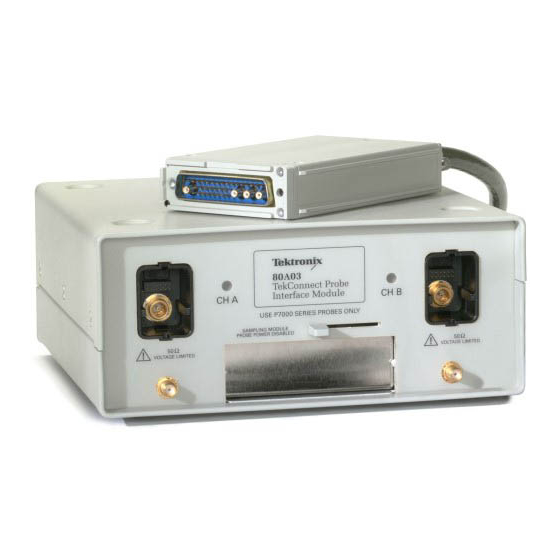
Getting Started Installing the TekConnect Probe Interface Module The following figure shows the TekConnect Probe Interface Module and locations of the sampling module and probe inputs. The extender cable on the rear of the interface connects to the mainframe front panel. Figure 2: TekConnect Probe Interface Module inputs and outputs Installing the TekConnect Probe Interface Module consists of the following steps: 1. -
Page 22: Figure 3: Extender Cable Connection To The Mainframe
Getting Started Connecting the Interface To install the TekConnect Probe Interface Module Extender Cable into the front panel of your mainframe, perform the following tasks: Module to the Main Instrument CAUTION. To prevent damage to the sampling module, never install or remove a module when the mainframe is powered on or when either input connector is left unprotected. -
Page 23: Figure 4: Installing The Sampling Module Into The Tekconnect Probe Interface Module
Getting Started Installing the Sampling To install the sampling module into the front panel of the TekConnect Probe Interface Module, perform the following tasks: Module CAUTION. Sampling modules are inherently vulnerable to static damage. Always observe static-safe procedures and precautions as outlined in your sampling module user manual. -
Page 24: Figure 5: Connecting The Sampling Module
Getting Started Installing the Semi-Rigid To provide a signal path between the sampling module and the TekConnect Probe Interface Module, perform the following tasks: SMA Connector Cables 1. Connect your wrist strap to the antistatic connector on the front of the mainframe. -
Page 25: Figure 6: Installing Tekconnect Probes
Getting Started Installing the TekConnect The TekConnect probe features a spring-loaded latch that provides audible and tactile confirmation that a reliable connection has been made to the TekConnect Probe Probe Interface Module. NOTE. It is not necessary to power off the mainframe when removing or installing a TekConnect probe. -
Page 26: Performing A Functional Check
Refer to the following table for a list of recommended equipment. Table 4: Recommended equipment for performing a functional check Item description Recommended example Sampling oscilloscope or signal analyzer Tektronix DSA8200, CSA8000 or TDS8000 Sampling module Tektronix 80E02, 80E03, or 80E04 TekConnect probe Tektronix P7000 Series... -
Page 27: Figure 7: Equipment Setup For Functional Check
Getting Started Figure 7: Equipment setup for functional check 5. Set up the channel for test: a. On the mainframe, press the channel button to select the channel that is connected. The Channel button lights, the sampling module LED lights, and the selected channel on the mainframe becomes active. -
Page 28: Calibrating The Tekconnect Probe Interface Module
Getting Started NOTE. The mainframe displays the first six characters of the TekConnect probe model and truncates the remaining characters. For example, it will identify a P7350SMA probe as P7350S. The impedance value displayed for P7330, P7350, P7350SMA, P7513, and P7516 probes is for single-ended configuration. -
Page 29: Nulling Offset Errors
Getting Started Nulling Offset Errors Use the following procedure to minimize the probe offset when using the 80A03 TekConnect Probe Interface Module. CAUTION. Always plug in the 80A03 Module and the 80E0x modules with the oscilloscope power off. Failure to do so may result in equipment damage. Setup Connect the equipment in the following order: Figure 8: Setup for Nulling Offset Errors... -
Page 30: Figure 9: Compensation Screen
Getting Started NOTE. This procedure must be performed with the probe set to the attenuation Procedure and mode, (if applicable), that you intend to take measurements with. The internal signal path changes with these settings and the stored probe offset values will not be accurate for other settings. - Page 31 Getting Started 4. In the Compensation screen: a. Select Compensate and Save in the Select Action box. b. Select Module from the drop-down menu beneath the Select Action box. c. Select the oscilloscope channel number that you are using from the drop-down menu beneath the Select Action box.
- Page 32 Getting Started 80A03 TekConnect Probe Interface Module Instruction Manual...
-
Page 33: Operating Basics
Operating Basics This section contains information you need to operate the 80A03 TekConnect Probe Interface Module. Understanding the Controls The 80A03 TekConnect Probe Interface Module front panel has one multi-color LED for each channel. During power on and normal operation, the LEDs report red, green, or off as explained below. -
Page 34: Triggering The Mainframe
Table 5: Recommended equipment for triggering setups To trigger only To trigger and view a signal Tektronix DSA8200 and CSA8000 or TDS8000 Series instrument Tektronix DSA8200, CSA8000, CSA8000B, CSA8200, TDS8000, TDS8000B, or TDS8200 instrument Tektronix 80A03 TekConnect Probe Interface Module... -
Page 35: Figure 10: Removing The Semi-Rigid Cable
Operating Basics Triggering the Mainframe To set up the TekConnect Probe Interface Module to trigger your mainframe, do the following: 1. Remove the semi-rigid cable that connects the CH B TekConnect Probe Interface Module to the sampling module. (See Figure 10.) Figure 10: Removing the semi-rigid cable 2. -
Page 36: Figure 11: Setup For Triggering The Mainframe Using The 80A03 Tekconnect Probe Interface Module
Operating Basics Figure 11: Setup for triggering the mainframe using the 80A03 TekConnect Probe Interface Module The mainframe responds to the CH A probe as though it were connected to the vertical sampling channel: The Trigger probe is serviced and controlled by the mainframe CH B vertical channel controls. -
Page 37: Figure 12: Trigger Offset Indicator
Operating Basics Figure 12: Trigger offset indicator NOTE. Rotation of the control knob for this configuration is reversed. Clockwise rotation introduces a negative offset adjustment, which provides a negative trigger level. Counterclockwise rotation introduces a positive offset and a positive trigger level. -
Page 38: Figure 13: Setup For Triggering The Mainframe And Viewing Signals Using The 80A03 Tekconnect Probe
Operating Basics Triggering and Viewing To set up the TekConnect Probe Interface Module to trigger your mainframe, do the following: Signals on the Mainframe 1. Remove the semi-rigid cable that connects the CH B TekConnect Probe Interface Module to the sampling module. 2. -
Page 39: Sampling Module Incompatibility
Operating Basics If you use the mainframe Trigger Direct input, it is recommended that you set the trigger level to 0 volts. With this configuration, you can control the trigger level by directly assigning the vertical offset for the CH B probe at the probe tip. Because the offset control in the probe affects the signal level at its output, this method of vertical offset adjustment provides calibrated trigger level operation. - Page 40 Operating Basics 80A03 TekConnect Probe Interface Module Instruction Manual...
-
Page 41: Reference
10X attenuator. Where possible, connect your cables to the signal source first, and to the sampling module second. You can use a Tektronix 80A02 EOS/ESD Protection Module to protect the sensitive input stage of sampling module from damage due to electro-overstress (EOS) and electro-static discharge (ESD) from the device under test (DUT). - Page 42 CAUTION. To prevent damage from electrostatic discharge, install 50 Ω terminations (Tektronix part number 015-1022-xx) on the sampling-module connectors before removing the sampling modules from a main instrument (mainframe) or when it is not in use. Store the sampling module in a static-free container, such as the shipping container.
-
Page 43: Specifications
Specifications This section lists the electrical, environmental, and physical characteristics of the 80A03 TekConnect Probe Interface Module. Specifications listed in this section are guaranteed unless labeled "typical". Typical specifications are provided for your convenience and are not guaranteed. The electrical characteristics listed in the table below are valid when the 80A03 TekConnect Probe Interface Module operates within the environmental conditions listed below. -
Page 44: Figure 14: Insertion Loss
Specifications Table 8: Physical characteristics Characteristic Description Weight 2.04 kg (4.5 lbs) Dimensions Height: 110 mm (4.250 in) Width: 70 mm (2.750 in) Depth: 42 mm (1.625 in) Cable length, nominal 1 m (3.28 ft) Does not include accessories and shipping container. The graphs of insertion loss and return loss are as follows: Figure 14: Insertion loss 80A03 TekConnect Probe Interface Module Instruction Manual... -
Page 45: Figure 15: Return Loss
Specifications Figure 15: Return loss 80A03 TekConnect Probe Interface Module Instruction Manual... - Page 46 Specifications 80A03 TekConnect Probe Interface Module Instruction Manual...
-
Page 47: Maintenance
Maintenance This section contains information you can use to clean and maintain your equipment. Inspecting and Cleaning Remove accumulated loose dust from the TekConnect Probe Interface Module and sampling module with a soft cloth or brush. Remaining dirt may be removed with a soft cloth dampened with a mild detergent and water solution, or use isopropyl alcohol. -
Page 48: Replacing Parts
Maintenance Product Requires Service The following conditions indicate an internal failure: No LED activity at power on LEDs are inactive on a single channel LED response is inconsistent when connecting the same probe alternately to both channels Replacing Parts Refer to the Replaceable Parts section for a list of customer replacement parts. (See page 33, Replaceable Parts.) Repackaging for Shipment If the original packaging is unfit for use or not available, use the following... -
Page 49: Replaceable Parts
This section contains a list of the replaceable parts for the 80A03 TekConnect Probe Interface Module. Use this list to identify and order replacement parts. Parts Ordering Information Replacement parts are available through your local Tektronix field office or representative. Changes to Tektronix products are sometimes made to accommodate improved components as they become available and to give you the benefit of the latest... -
Page 50: Figure 16: 80A03 Replaceable Parts
Replaceable Parts Abbreviations Abbreviations conform to American National Standard ANSI Y1.1-1972. Figure 16: 80A03 replaceable parts 80A03 TekConnect Probe Interface Module Instruction Manual... -
Page 51: Table 10: Replaceable Parts
Replaceable Parts Table 10: Replaceable parts Fig. & index Tektronix Serial no. Serial no. number part number effective discont’d Name & description 16-1 200-4827-00 COVER; EXTERIOR,AL;GOLDEN GATE,SAFETY CONTROLLED 174-4856-00 CA,ASSY;SP,ELEC,SEMI-RIGID COAX, 0.141 OD,PLATED 407-4954-01 BRACKET ASSY,TEKCONNECT;ACQUISITION,AL MODULAR KIT; RECEPTACLE; PROBE ASSEMBLY, LATCHING, SAFETY...
Need help?
Do you have a question about the TekConnect 80A03 and is the answer not in the manual?
Questions and answers