
Related Manuals for Telair ENERGY 4000B


Summary of Contents for Telair ENERGY 4000B
- Page 1 GENERATORS ENERGY 4000B ENERGY 4000GAS USER'S OPERATING INSTRUCTION AND INSTALLATION MANUAL ENGLISH V. 013 - MARCH 2008 Vers. 013 Energy 4000 B / 4000 GAS...
-
Page 2: Table Of Contents
INDEX 1 FOREWORD ............................. 5 1.1 Purpose and scope of this manual ..................... 5 1.2 Symbols and Definitions ......................5 1.3 General Information ........................5 2 GENERATING SET IDENTIFICATION DATA .................. 6 2.1 Components (Fig. 1) ........................6 2.2 Identification plate (Fig. 2) ......................6 2.3 Dimensions .......................... - Page 3 9 FIRE-PREVENTION ........................20 WIRING DIAGRAM ENERGY 4000 B ....................21 WIRING DIAGRAM ENERGY 4000 GAS .................... 22 DRAWING FOR SPARE PARTS LIST ENERGY 4000 B..............23 DRAWING FOR SPARE PARTS LIST ENERGY 4000 GAS .............. 24 GENERAL INFORMATION FOR ENERGY 4000 GAS ONLY ............28 WIRING DIAGRAM INSIDE THE GENERATOR FOR THE CABLES OF THE LPG SYSTEM ..
- Page 4 Via E. Majorana , 49 48022 Lugo (RA) ITALY "CE" COMPLIANCE STATEMENT Under Machine Directive 89/392/EEC, attachment II A We hereby represent that the generator-set, the data concerning which appear below, has been designed and built to correspond to the essential safety and health requirements laid down by the European Directive on Machine Safety.
-
Page 5: Foreword
1 FOREWORD 1.2 Symbols and Definitions Refer carefully this "Graphic safety symbols” have been employed in manual before performing any operation on this booklet to identify different levels of danger or the air conditioner. important information. 1.1 Purpose and scope of this manual This means that you must This manual has been drawn up by the pay attention to avoid serious consequences... -
Page 6: Generating Set Identification Data
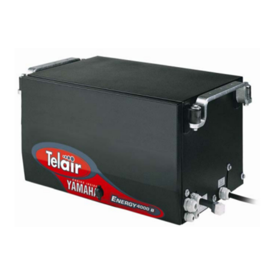
GENERATING SET IDENTIFICATION DATA 2.1 Components (Fig. 1) Sound-proofing box Supporting brackets Access door Access door closure Technical features sticker Anti-vibration support Anchoring bracket Electronic control panel 2.3 Dimensions Figure 3 shows the dimensions of the generating sets. 2.2 Identification plate (Fig. 2) Generating set model Model code number Serial number... -
Page 7: Fiche Technique
2.4 Fiche technique ENERGY ENERGY 4000 B 4000 GAS ENGINE Single cylinder, 4 stroke petrol, Single cylinder, 4 stroke GPL, Type head valves, air cooling head valves, air cooling Yamaha MZ 250 Yamaha MZ 250 GAS Engine Displacement 70 x 57 70 x 57 Bore x Stroke 2,0 l/h... -
Page 8: Weight
4 INSTALLAZIONE Do not turn the package 4.1 Preliminary information upside down. The right position is the one shown by the symbol printed on the package Before installing conditioner, it is absolutely necessary to read 3.2 Weight these instructions, in order not to make any Total weight including packing: mistakes during installation. -
Page 9: Wiring Connection Instructions
wiring system. This serves to insulate the generating set when it is connected to an outside 4.3 Wiring connection instructions To connect the loads to the generating set, use a power mains. three-pole power cable working according to Connect the relay proceeding as follows: current laws. -
Page 10: Battery Charger
The soundproofing box is equipped with two cable pressers used to let through the battery connection cables (Fig. 7 ref. 3). Always fit a 70 A fuse onto the positive cable connecting the generating set to the positive pole of the battery. 230 Volt AC 230 Volt AC 12 Volt CC... -
Page 11: Fuel Reserve
Should it not be possible to respect this depending on the kind of installation. The fuel maximum level difference between the fuel tank cut-off cock (Fig. 13 ref. 3) can also be and the generating set, you can install an electric screwed onto two different threaded pipe fuel pump which comes as an option (code fittings (Fig. - Page 12 To power the fuel pump, proceed as follows: • connect the negative pole of the pump to the relevant connector inside the generating set (Fig. 16 ref. 1); • connect the positive pole of the pump to the positive terminal of the battery (Fig. 5 ref. 3). To perform the power connections, use a two- pole cable with a cross-section of at least 1 mm Vers.
-
Page 13: Connecting The Additional Silencer
4.10 Connecting the additional silencer To further cut down the sound level of the generating set, one can install an additional silencer on the outside (code 05468). The additional silencer kit (code 05422) consists of a silencer (Fig. 17 ref. 1), a stretch of flexible steel hose (Fig. -
Page 14: Operating Instructions
5 OPERATING INSTRUCTIONS 6 USING THE GENERATING SET ENERGY series generators are made from petrol or gas internal combustion engines connected to 6.1 Starting up the generating set an alternator that can produce both alternating and direct electrical current. The generating sets The generating sets are provided with a remote are assembled inside a steel plate casing, electronic control panel which allows you to... -
Page 15: Turning The Generating Sets Off
6.4 Suggestions To make the best use of the generating sets, remember that even small overloads - if they last for some time - will make the temperature cut-off contact open (Fig. 22 ref. 3). During the running-in period, do not subject the new engine to a load higher than 70% of the rated load, at least for the first 50 running hours. -
Page 16: Maintenance Instructions
Reason: 50 hours have gone by since oil was last 7 MAINTENANCE INSTRUCTIONS changed, and you must check its level. How to turn it off: once you have checked the level, Use only original spare press the partial counter push-button (fig. 21 ref. 9). parts. -
Page 17: Maintenance Operations Calling For Qualified Personnel
• Unscrew the engine oil level reference cap 7.4.1 Engine oil replacement Use multigrade detergent oil for four-stroke petrol and clean the dipstick (Fig. 23 ref. 1). engines having a SAE viscosity suited to the • Put the dipstick back in without screwing. climate the generating set is working in (see table •... -
Page 18: Air Filter Maintenance
• Take the cap off the spark plug (Fig. 26 ref. 2) country where such operations and using the special wrench take out the performed. plug. 7.4.2 Air filter maintenance • Perform a sight check. Replace in case of obvious war or if the insulator is broken or A dirty air filter will reduce cracked. -
Page 19: Voltage Adjustment
7.4.4 Voltage adjustment Adjust the voltage when the engine is hot, no load is present and the generating set is running. Check the voltage of the generating set using a voltmeter via a 230 V vehicle socket. The voltage must be between 230 V and 245 V without any user being attached. -
Page 20: Dismantling
8.2 Dismantling 9 FIRE-PREVENTION Should you have to dismantle the generating set, In case of fire, never open the hood of the refer to specialised shops. generating set and use only approved type fire extinguishers. Never use water to put out flames in the generating unit. -
Page 21: Wiring Diagram Energy 4000 B
WIRING DIAGRAM ENERGY 4000 B Vers. 013 Energy 4000 B / 4000 GAS... -
Page 22: Wiring Diagram Energy 4000 Gas
WIRING DIAGRAM ENERGY 4000 GAS Vers. 013 Energy 4000 B / 4000 GAS... -
Page 23: Drawing For Spare Parts List Energy 4000 B
DRAWING FOR SPARE PARTS LIST ENERGY 4000 B Vers. 013 Energy 4000 B / 4000 GAS... -
Page 24: Drawing For Spare Parts List Energy 4000 Gas
DRAWING FOR SPARE PARTS LIST ENERGY 4000 GAS Vers. 013 Energy 4000 B / 4000 GAS... - Page 25 Descrizione Dèsignation Denomination Pos. Code Q.tà Description Bezeichnung Descripcion Cofano superiore Capot supérieur Bovenste kap 02015 N. 1 Upper cowling Obere Haube Capo superior Anti-vibr. 30x30 I 8MA FF SH 45 AN- Trillingsdemp. 30x30 I 8MA FF SH 45 Antivibrante TIHUILE OLIEWEREND 00632...
- Page 26 Descrizione Dèsignation Denomination Pos. Code Q.tà Description Bezeichnung Descripcion Dado plastica PG16 Ecrou plastique PG16 Moer plastic PG16 00369 N. 3 plastic nut Kunststoffmutter PG16 Tuerca plástico PG16 Pressacavo SKINTOP PG9 Serre-câble SKINTOP PG9 Kabelklem SKINTOP PG9 00863 N. 2 SKINTOP cable gland Kabelschelle SKINTOP PG9 Prensacable SKINTOP PG9...
- Page 27 Descrizione Dèsignation Denomination Pos. Code Q.tà Description Bezeichnung Descripcion Pannello di controllo ENERGY Tableau/contrôle ENERGY Schakelpaneel ENERGY 03789 N. 4 ENERGY control panel Bedienpanel ENERGY Panel de control ENERGY Cavo 5 m da generatore a Pannello Câble 5 m du Générateur au Pan- 5 m kabel van generator naar di controllo neau de Contrôle...
-
Page 28: General Information For Energy 4000 Gas Only
GENERAL INFORMATION FOR ENERGY 4000 GAS ONLY CAUTION IMPORTANT • Set the solenoid valves in vertical position. • Keep the air filter clean. 1 Cable n° 1, brown color, connected to the POSITIVE pole of the battery and to a terminal of the primer push button. -
Page 29: Wiring Diagram Inside The Generator For The Cables Of The Lpg System
WIRING DIAGRAM INSIDE THE GENERATOR FOR THE CABLES OF THE LPG SYSTEM FOR ENERGY 4000 B ONLY 1 Brown cable from the positive terminal of the battery to any of the terminals of the primer push button. 2 Brown cable from the positive terminal of the battery to the positive terminal of the gas solenoid valve. -
Page 30: Hose Connection Between The Bottle And Reducer For Energy 4000 Gas
HOSE CONNECTION BETWEEN THE BOTTLE AND REDUCER FOR ENERGY 4000 GAS Fig. A: The generator (1) is supplied by TELAIR complete with special pressure reducer (2) and one metre long gas hose (3) to connect the pressure reducer to the generator. -
Page 31: General Warranty Terms
GENERAL WARRANTY TERMS TELAIR guarantees its products against any material and/or manufacturing faults and defects. The entitlement to warranty cover for new engines is valid for a period of 24 months from the time of handing over to the end user, or for a maximum of 1000 operating hours, whichever of these limits is reached first. - Page 32 Contro Copertina Telair Vers. 013 Energy 4000 B / 4000 GAS...
Need help?
Do you have a question about the ENERGY 4000B and is the answer not in the manual?
Questions and answers