Table of Contents
Advertisement
Advertisement
Chapters
Table of Contents

Related Manuals for Manitou 200 ATJ


Summary of Contents for Manitou 200 ATJ
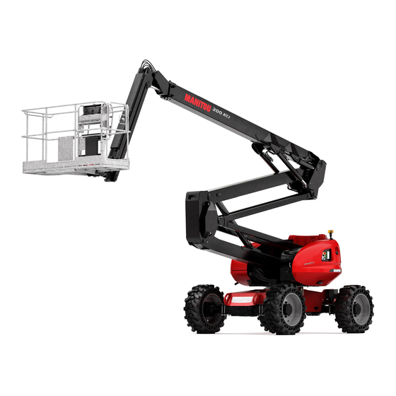
- Page 1 TEL : 33 (0)2 40 09 10 11 YOUR DEALER 547386 EN (01 / 06 / 2007) ACCES PLATFORM 200 ATJ OPERATOR’S MANUAL THIS INSTRUCTION LEAFLET MUST BE KEPT PERMANENTLY ON THE ACCESS PLATFORM AND BE READ AND UNDERSTOOD BY THE OPERATORS.
- Page 2 The platform has been designed and pro- duced to enable you to work at high level in complete safety. Before its delivery, MANITOU and the concessionaire have carefully inspected the platform so that you receive it in perfect operating condition.
- Page 3 1 - OPERATING AND SAFETY INSTRUCTIONS 2 - DESCRIPTION 3 - MAINTENANCE 4 - ELECTRICITY 5 - MAINTENANCE HANDBOOK 01/06/2007 1ST DATE OF ISSUE THE TEXTS AND ILLUSTRATIONS IN THIS DOCUMENT MUST NOT BE REPRODUCED EITHER WHOLLY OR IN PART.
- Page 4 FRONT REAR...
- Page 5 1 - OPERATING 1 - OPERATING AND SAFETY AND SAFETY INSTRUCTIONS INSTRUCTIONS 1 - 1...
-
Page 6: Table Of Contents
TABLE OF CONTENTS 1 - 5 ENUINE SPARE PARTS 1 - 6 NSTRUCTIONS TO THE COMPANY MANAGER PREAMBLE 1 - 6 THE OPERATOR 1 - 6 THE PLATFORM 1 - 6 A - THE PLATFORM’S SUITABILITY FOR USE 1 - 6 B - ADAPTING THE PLATFORM TO THE USUAL ENVIRONMENTAL CONDITIONS 1 - 6 C - MODIFYING THE PLATFORM... -
Page 7: Genuine Spare Parts
- Only the manufacturer knows the details of the access platform design and therefore has the best technological capability to carry out maintenance. ORIGINAL REPLACEMENT PARTS ARE DISTRIBUTED EXCLUSIVELY BY MANITOU AND ITS DEALER NETWORK. The list of the network of the dealers is available on the site MANITOU www.manitou.com 1 - 5... -
Page 8: Instructions To The Company Manager
A - THE PLATFORM’S SUITABILITY FOR USE - MANITOU hase ensured that this platform is suitable for use under the standard operating conditions defined in this opertor’s manual, with an overload test coefficient of 1.25 and an operationnal test coefficient of 1,1, as stipulated in standardised norm EN 280 for MPLP (Mobile Personnel Lifting Platforms). -
Page 9: C - Modifying The Platform
For operation inder average climatic conditiuons, i.e.: - 15°C and + 35°C, correct levels of lubricants in all the circuits are checked in production. For operation under more severe climatic conditions, before starting up, it is necessary to drain all the circuits, then ensure correct levels of lubricants using lubricants properly suited to the relevant ambient temperatures. -
Page 10: Instructions For The Operator
INSTRUCTIONS FOR THE OPERATOR REAMBLE WHENEVER YOU SEE THIS SYMBOL IT MEANS : WARNING ! BE CAREFUL ! YOUR SAFETY OR THE SAFETY OF THE PLATFORM IS AT RISK. the risk of accident while using, servicing or repairing your platform can be restricted if you follow the safety instructions safety measures detailed in these instruction. -
Page 11: C - Maintenance
C - MAINTENANCE - The operator must immediately advise his superior if his platform is not in good working order or does not comply with the safety notice. - the operator is prohibited from carrying out any repairs or adjustements himself, unless he has been trained for this purpose. -
Page 12: Driving Instructions
- Safety helmets must be worn. - MANITOU recommends a safety harness in the operator’s size be provided when the platform is in use (for the harness attachement in the basket , see 2 - DESCRIPTION : INSTRUMENTS AND CONTROLS). -
Page 13: D - Visibility
- Do not allow anybody to come near the working area of the platform or pass beneath an elevated load. To do this, mark your operating area with warning signs. - Travelling on a longitudinal slope : • Ensure that you adapt the platform’s travelling speed by controlling the speed with the travelling manipulator. - Take into account the platform’s dimensions and its load before trying to negotiate a narrow or low passageway. -
Page 14: E - Starting The Platform
E - STARTING THE PLATFORM PLATFORMS WITH IC ENGINES SAFETY NOTICE - Never try to start the platform by pushing or towing it. Such operation may cause severe damage to the transmission. In case of necessity, towing requires the platform to be set for free-wheeling (see : 3 - MAINTENANCE). - If using an emergency battery for start-up, use a battery with the same characteristics and respect battery polarity when connecting it. -
Page 15: F - Driving The Platform
- If any error messages are constantly displayed or the machine maintenance light is flashing, return the key to the neutral position. - Set the battery cut-off to the OFFposition. - Immediately take the necessary measures. F - DRIVING THE PLATFORM SAFETY NOTICE Operators should be aware of the risks connected with using the platform, notably: - Risk of losing control. -
Page 16: G - Stopping The Platform
G - STOPPING THE PLATFORM SAFETY NOTICE - Never leave the ignition key in the platform during the operator's absence. - Make sure that the platform is not stopped in any position that will interfere with the traffic flow and at less than one meter from the track of a railway. -
Page 17: Instructions For Welding And Blow Torch Work On The External Structure
NSTRUCTIONS FOR WELDING AND BLOW TORCH WORK ON THE EXTERNAL STRUCTURE Ensure that there are no hydraulic or electrolyte leaks on the platform. When welding, work in the opposite direction from the control console to avoid sparks damaging it. Any welding and cutting (blow torch) work from the basket on a building’s metallic structures requires the following precautions to be taken: A -WITH ELECTRIC WELDING EQUIPMENT - It is essential that the machine has a discharge braid connecting the platform’s chassis to the ground. -
Page 18: Platform Maintenance Instructions
PLATFORM MAINTENANCE INSTRUCTIONS ENERAL INSTRUCTIONS - Ensure the area is sufficiently ventilated before starting the platform. - Wear clothes suitable for the maintenance of the platform, avoid wearing jewellery and loose clothes. Tie and protect your hair, if necessary. - Stop the engine before conducting any work on the platform, remove the ignition key and disconnect the “Minus” battery terminal. -
Page 19: Electricity
Ensure that all consumables and replacement parts are disposed of safety, in an environmentally friendly mannerue. LECTRICITY - Do not drop metallic items on the battery (between the “Plus” and “Minus terminals”). - Disconnect the battery or batteries before working on the electrical circuit. - The electrical box must only be opened by authorized personnel. -
Page 20: If The Platform Is Not To Be Used For A Long Time
The following recommendations are intended to prevent the platform from being damaged when it is withdrawn from service for an extended period. For these operations, we recommend the use of a MANITOU protective product, reference 603726. Instructions for using the product are given on the packaging. -
Page 21: Charging The Batteries
HARGING THE BATTERIES - In the case of electric platforms, in order to preserve the batteries’life and their capacity, check them periodically and keep the charge level constant (see : 3 - MAINTENANCE). ROTECTING THE PLATFORM - Protect cylinder rods which will not be retracted, from corrosion. - Wrap the tyres. - Page 22 SAFETY STICKERS 598897 ARRIERE AVANT 597648 1 - 20...
- Page 23 ESCRIPTION 1 - WHITE ARROW 2 - BLACK ARROW 3 - WHEEL LOAD 4 - MANUAL CONTROL PROCEDURE 5 - SAFETY INSTRUCTIONS/ WASHING RECOMMENDATION/ TOWING 6 - ANCHORING HOOK 7 - BASKET INSTRUCTIONS / LOADING CAPACITY 8 - BACKUP PUMP 9 - HYDRAULIC OIL 10 - DIESEL 11 - PLATFORM KEY LOCATION...
- Page 24 EANING 1. W HITE ARROW Shows the direction of travel in forward gear. When the turret, arm structure and basket rotate by 180° relative to the frame, the travel commands are reversed. Identify the direction of movement by looking at the arrows on the frame and the basket control panel.
- Page 25 AFETY INSTRUCTIONS Read the safety and operating instructions before starting the platform. OWING This sticker indicates that the machine must not be towed in the event of breakdown. ASHING RECOMMENDATION It is strictly forbidden to direct a high-pressure cleaning jet onto the control buttons and electrical components.
- Page 26 8. B ACKUP PUMP This backup pump must be used only in the event of a problem or failure. 9. H YDRAULIC OIL Indicates that this tank is designed to hold hydraulic oil only. NOTE: See MAINTENANCE: LUBRICANTS 597652 10. D IESEL Indicates that this tank is designed to hold fuel for diesel vehicles only.
- Page 27 12. D – ANGER KEEP AWAY It is strictly prohibited to cross or park under the structure (arms, scissor lift, pendular arm, basket...) or within the platform's radius of movement. 679450 13. D ANGER RISK OF CUTS AND CRUSHING INJURIES It is strictly prohibited to put your fingers or any other part of the body in the lifting mechanism components (arms, scissor lift, pendular arm)...) risk of cuts and crushing injuries.
- Page 28 16. M ADE IN RANCE This sticker indicates that the machine was manufactured in France. 597648 ADHESIF Couleurs : bleu (pantone 072) 17. A NTIFREEZE This sticker means that there is antifreeze in the IC engine. If the antifreeze protection has different characteristics from the original product, the -30°C or -40°C box is ticked.
- Page 29 2 - DESCRIPTION 2 - DESCRIPTION 2 - 1...
- Page 30 2 - 2...
- Page 31 TABLE OF CONTENTS 2 - 4 LATFORM IDENTIFICATION 2 - 8 HARACTERISTICS 200 ATJ 2 - 12 IMENSIONS 2 - 14 LATFORM OPERATION 2 - 16 ONTROL INSTRUMENTATION 2 - 20 ROUND BACKUP AND MAINTENANCE STATION 2 - 28 ASKET COMMAND AND CONTROL STATION...
- Page 32 IDENTIFICATION OF THE ACCESS PLATFORM As our policy is to promote a constant improvement of our products, our range af access platforms may indergo certain modifications, without obligation for us to advise our customers. When you order parts, or when you require any technical information, always specify : NOTE : For the owner’s convenience, it is recommended that a note of these numbers is made in the spaces provided, at the time of the delivery...
- Page 33 YDROSTATIC PUMP - Pump Nr - Codification type - Manufacturer’s Nr - Year of manufacture RONT AXLE ASSEMBLY - Axle type - Serial Nr - Maker’s Nr EAR AXLE ASSEMBLY - Axle type - Serial Nr - Maker’s Nr 2 - 5...
- Page 34 BEFORE STARTING UP A PLATFORM FOR THE 1ST TIME NTRODUCTION - Our access platforms have been designed for easy handling by the operator and maximum maintenance easiness for the mechanic. - However, before commencing to operate the access platform, the user should carefully read and understand the various chapters of this manual which has been provided to solve driving and maintenance problems.
- Page 35 YRES - Make sure that the wheel nuts are correctly tightened (See chapter : SERVICING SCHEDULE - B EVERY 3 MONTHS OR EVERY 150 WORKING HOURS SERVICE) UEL SYSTEM - Check that all fuel lines are secured. - If necessary drain the fuel filter and bleed the fuel system of air. LECTRICAL CIRCUIT - Check the level and the density of the electrolyte in the battery.
-
Page 36: Characteristics
CHARACTERISTICS NGINE - Type PERKINS 404C22 atmospheric diesel - Number of cylinders 4 in line - Numbere of phases - Injection system Direct injection - Firing sequence 1.3.4 2 - Cubic capacity 2216 cc - Bore 84 mm - Stroke 100 mm - Volume ratio 23.3 : 1... - Page 37 UXILIARY HYDRAULIC CIRCUIT - Pump type Gear pump . Cubic capacity 22.5 cm - Lifting, tilting, telescope, steering, rotation circuit . Flow at max. revs empty 56 L/mn . Pressure 200 Bar - Filtration . Pressure 10 Microns ONNECTION USES - F1 (1 Fig A) +BAT calculator UPC 30 30 A...
- Page 38 With two people in the basket 70 kg - Hydrostatic transmission 4 wheel drive 4 wheel steer - Turret rotation: 200 ATJ standard: 350° 200 ATJ (continuous rotation option) continuous - Operating speed 0.8 km/h - Travel speed: Tortoise 2.5 km/h Ramp 2.5 km/h...
- Page 39 2 - 11...
-
Page 40: Dimensions 200 Atj
DIMENSIONS 200 ATJ 8475mm 6260mm 2400mm 2700mm 2840mm 2400mm 430mm 340mm 1300mm 3950mm 5000mm 7450mm 3030mm 420mm 2 - 12... - Page 41 18270mm 4155mm 11475mm 8090mm 320mm 10320mm 2 - 13...
-
Page 42: Platform Operation
- MANITOU lifting platforms are designed to carry personnel, their tools and supplies (within the authorized weight limit, see paragraph on "SPECIFICATIONS") to the desired working height, to reach places which are difficult to access, above installations or buildings. - Page 43 AFETY SLOPE When the platform has reached the maximum authorised slope (see chapter on: CHARACTERISTICS), LED 34* on the basket control panel flashes regularly. Furthermore, the buzzer 41* in the basket sounds intermittently. All "AGGRAVATING" arm elevation and telescope extension movements a r e p r o h i b i t e d f o r...
-
Page 44: Round Backup And Maintenance Station
INSTRUMENTS AND CONTROLS A - G ROUND BACKUP AND MAINTENANCE STATION 2 - 16... - Page 45 A - G ROUND BACKUP AND MAINTENANCE STATION 1 - IGNITION SWITCH 2 - START CONTROL BUTTON 3 - FLOOR / PLATFORM CONTROL SELECTOR SWITCH 4 - EMERGENCY STOP 5 - ENGINE STARTING ASSISTANCE IN THE EVENT OF COLD TEMPERATURES 6 - INTERFACE SCREEN 7 - SCREEN INFORMATION VALIDATIONS BUTTONS 8 - BASKET DOWNWARD TILT BUTTON...
- Page 46 B - B ASKET COMMAND AND CONTROL STATION 2 - 18...
- Page 47 B - B ASKET COMMAND AND CONTROL STATION 19 - CONSOLE PROTECTIVE COVER 20 - UPPER ARM RAISING & LOWERING AND TURRET ROTATION CONTROL LEVER 21 - LOWER ARM RAISING & LOWERING AND TELESCOPE EXTENSION & RETRACTION CONTROL 22 - PLATFORM FORWARD / REVERSE MOVEMENT AND RIGHT / LEFT CONTROL LEVER 23 - EMERGENCY STOP 24 - "PRE-HEATING”...
- Page 48 GROUND BACKUP AND MAINTENANCE STATION 1 - I GNITION SWITCH This key-operated switch has two positions. POSITION 1 - Stop the IC engine. POSITION 2 - Powers and automatically pre-heats the engine. 2 - S TART CONTROL BUTTON BUTTON 3 - Starting the IC engine.
- Page 49 4- E MERGENCY STOP This switch cuts off all movement by the machine in the event of an anomaly or any danger arising. - Press the knob to cut off all movement. - Turn the knob a quarter of a turn to the right to deactivite it (the switch returns to its original position automatically).
- Page 50 6 - I NTERFACE SCREEN This sreen enables you to see all the start-up, parametering, maintenance and platform faults steps. NOTA : The current system time is displayed at the top of each page. 7 - S CREEN INFORMATION VALIDATION BUTTONS - These buttons enable you to validate the various data on the screens.
- Page 51 4 - DESCRIPTION UNDER NORMAL USE (WITH NO FAULTS DISPLAYED ON THE SCREEN) 8 - B ASKET DOWNWARD TILT BUTTON 9 - B ASKET UPWARD TILT BUTTON - These buttons enables you to correct the basket level or to fold the basket completely in transport position.
- Page 52 11 - L OWER ARM RAISING LOWERING BUTTONS - These buttons enable you to raise and lower the lower arms. A : RAISING THE LOWER ARMS - Hold contactor 3 in position 2 and press A. B : LOWERING THE LOWER ARMS - Hold contactor 3 in position 2 and press B.
- Page 53 15 - B LOCKING THE TURRET FROM ROTATING - This pin must be used when the platform is being transported by truck or some other means of transport (Train, etc...), to stop the turret from rotating. - Remove the “clip”, and swiwel the pin to the left. - Push the pin into the hole in the turret.
- Page 54 18 - A UDIBLE ALARM This buzzer (fixed to the outside of the hydraulic unit on the telescopic arm side) is activated by pressing button 29 on the basket command and control panel. 19 - E MERGENCY PUMP BUTTON This button is used to perform all basket movements for a return to the ground in the event of breakdown (see chapter on : RESCUE PROCEDURE).
- Page 55 2 - 27...
-
Page 56: Basket Command And Control Station
BASKET COMMAND AND CONTROL STATION 20 - U & PPER ARM RAISING LOWERING AND TURRET ROTATION CONTROL LEVEL - This lever rep.20 enables you to raise the upper arm and rotate the turret. NOTA : This lever operates under proportional control enabling precision when approaching. - Page 57 22 - P LATFORM FORWARD REVERSE MOVEMENT CONTROL LEVER - This lever rep.22 enables you to move the platform. - You must press trigger A and the dead man’s pedal (voir Rep.40) to make any movements via the platform’s control box. - No commands are possible when the pedal or the trigger A is released.
- Page 58 24 - "P " HEATING INDICATOR LIGHT This indicator light illuminates when the machine is switched on: - Or turn the ignition key on the base (time identical to bargraph evolution on the screen). - Or by re-arming the Emergency Stop on the basket’s console on the platform.
- Page 59 27 - 28 S ELECTOR FOR STEERING MODE AND AXLE ASSEMBLY REALIGNMENT This contactor has three positions. POSITION 1 - Selects "Crab" mode. POSITION 2 - Selects 2-wheel drive mode. POSITION 3 - Selects 4-wheel drive mode. In this configuration, the available travel speeds are only: Tortoise or hare.
- Page 60 29 - A UDIBLE ALARM CONTROL BUTTON When you press button 29 , the audible alarm 41 sounds. 30 - D IFFERENTIAL LOCKING CONTROL BUTTON NB : This command must only be used during travel. The differential lock enables the 2 driven wheels to turn at the same speed.
- Page 61 32 - T RAVELLING SPEED SELECTOR SWITCH This contactor has 3 positions. POSITION 1 : TORTOISE (SLOW SPEED) POSITION 2 : RAMP (SLOW SPEED WITH FULL POWER) Only if crossing a very big ramp and only in reverse gear. POSITION 3 : HARE (HIGH SPEED), only with the direction mode selector set to 1 (rep.27: Crabwise movement) or 2 (rep.27: Movement with 2 wheel drive).
- Page 62 37 - B ASKET ROTATION SWITCH - This contactor enables you to rotate the basket right and left RIGHT ROTATION - Push the contactor to the right. LEFT ROTATION - Push the contactor to the left. 38 - B ASKET PENDULAR ARM SWITCH - This contactor enables you to raise and lower the pendular arm.
- Page 63 41 - B UZZER - This buzzer is actived when the machine has reached the maximum authorised tilt or is overloaded. - If intermittent : When the maximum authorised tilt threshold is crossed all movements are blocked, except for lowering the arms, thereby enabling the machine to return to an acceptable level.
- Page 64 SCREEN DISPLAY DIAGRAM User level DOTTED LINES Path possible only after entering a secret code. Fault FUEL JAUGE MAINTENANCE F AULT - Access to fault page by pressing the DEF key. 11 12 15 16 Fault TO BE DISPLAYED - Access to the fault page by pressing the DEF key.
- Page 65 View and Dealer / Hirer Level How to use the MENU and ESC keys MENU : - Secret code INACTIVE - SCREEN SETTING pages displayed. - Secret code ACTIVE - SETTING, MAINTENANCE, ENGINE menus displayed. ESC : - Returns you the previous sub-menu. SYSTEM PARAMETERS - Select a group of...
- Page 66 SCREEN DISPLAY - DIAGRAM TART UP PAGES - PRESENTATION page When the machine is switched on, an initialisation page briefly appears on the screen and then the Pre-heating page appears. - PRE-HEATING page The Pre-heating page appears during the adjustable pre-heating period and the bar graph increases in proportion to the pre-heating time elapsed.
- Page 67 - PRE-HEATING COMPLETED (OK) page When the pre-heating time has elapsed (bar graph full), an indication of “OK” is displayed if the system has not encountered any problems and then one of the Operating pages (6, 7, 8 ou 9) is displayed. 2 - 39...
- Page 68 PERATING PAGES - WORKING FROM THE BASE (NO FAULT PRESENT) page - WORKING FROM THE BASKET (NO FAULT PRESENT) page Selection of speed 1, 2 and 3 corresponding to the raising and lowering speeds for the arms from the basket: 1 - Slow speed 2 - Moderate speed 3 - High speed...
- Page 69 WORKING FROM THE BASE - FAULT FOR SPÉCIAL HANDLING PRÉ- SENT For the following pages, if several faults are detected, they appear in the operating page simultaneously and in a loop. NB : Faults 28 and 29 do not require to be displayed nor acknowledged and do not prevent use the machine.
- Page 70 AULT PAGES MAINTENANCE FAULTS These pages appear on the screen after you press the DEF button on Operating page 9 or press the OK button on page NB : These faults are triggered 10 hours before the end of the period between two maintenance operations.
- Page 71 FAULT TO BE DISPLAYED These pages appears on the screen after your press the DEF button on Fault page - MANIPULATOR FORWARD FAULT Page - LOWER ARMS MANIPULATOR FAULT Page - UPPER ARMS MANIPULATOR FAULT Page - TELESCOPE MANIPULATOR FAULT Page - TURRET ROTATION MANIPULA- TOR FAULT Page - Default...
- Page 72 FAULTS FOR SPÉCIAL HANDLING These pages appear on the screen after you press the DEF button on pages 24 à 27. - SLOPE FAULT Page - LIFTING PLATFORM OVERLOAD FAULT Page - COHERENCE FAULT Page - START-UP FAULT Page 2 - 44...
- Page 73 FAULTS TO BE ACKNOWLEDGED These pages appear directly on the screen and must be acknowledged by pressing the OK button. - SCREEN CAN NETWORK FAULT Page - ENGINE WATER TEMPERATURE FAULT Page - ENGINE OIL PRESSURE FAULT Page - BATTERY LOAD FAULT Page - UPPER/LOWER POWER SUPPLY FAULT Page - INDUCTIVE SENSOR FAULT...
- Page 74 ENU PAGE Menu page 44 provides a choice of three sub-menu group categories: SETTING, MAINTENANCE and SECRET CODE. You can change from one sub-menu group to another by pressing the upper PLUS/MINUS keys. You choose a sub-menu by pressing the lower PLUS/MINUS keys and conforming by pressing the OK button opposite the “OK”...
- Page 75 ETTINGS SUB MENU SCREEN SETINGS SUB-MENU - CONTRAST Page - SCREEN PARAMETERS REINITALISATION Page The page 39 appears when the OK button is pressed on 38 and 40. - BRIGHTNESS Page - TIME/DATE Page - SECRET CODE Page - SECRET CODE ENTRY Page 2 - 47...
- Page 76 SYSTEMS PARAMETERS SUB-MENU You can choose between groups (8 or 33 selon code) by using the lower PLUS/MINUS keys and then pressing OK. The parameters are set by using the lower PLUS/MINUS keys. - DATA BACKUP Page Page 46 appears; depending on the secret code there are eight or thirty three pages displayed on the screen : Code 0241 - 8 Pages : Display and change parameters Max speed settings...
- Page 77 AINTENANCE SUB MENUS MAINTENANCE COUNTERS SUB-MENU NB : When requesting pages 48, 49 and 50, a maintenance fault page may appear (pages 10 to 16) see the MAINTENANCE FAULTS paragraph. Code 1000 : Display counters Code 0241 : Visualisation et modification des compteurs - MAINTENANCE COUNTERS Page 1/3 - MAINTENANCE COUNTERS Page 2/3 - MAINTENANCE COUNTERS Page 3/3...
- Page 78 VIEW I/O SUB-MENU - VIEW INTOR Page Base, Basket, Screen - VIEW OUTTOR Page Base, Basket, Screen - VIEW INANA Page Manipulators, UPC Base, Fuel - VIEW INHSCE Page Base, Basket, UPC101 1, UPC101 2 - VIEW OUTANA, OUT PWM Page 2 - 50...
- Page 79 HISTORIC SUB-MENU - HISTORIC Page 34 faults classified by category over 25 pages. HISTORIC MAINTENANCE SUB-MENU - HISTORIC MAINTENANCE Page 8 maintenance categories with logs of the last 9 maintenance operations on 16 pages. 2 - 51...
-
Page 80: Use Of The Platform
USE OF THE PLATFORM TRANSPORT POSITION FRONT TRAVELLING REAR TRAVELLING EFORE STARTING THE PLATFORM - Check the following levels : . The IC motor’s oil. . The hydraulic oil reservoir. . The coolant. TARTING THE PLATFORM - Turn the ignition switch to position 2 to switch on the electrical systems. When the machine is switched on, a beep sounds in the basket. - Page 81 OVEMENT IN TRANSPORT MODE WORK MODE Before moving and using the machine, release lock 1 on the turret (see Fig. A). The platform has two separate movement modes: transport mode (Fig. D) and work mode (Fig. E) (direction of movement (Fig. C)). - Transport mode: The platform arms are in low position, the pendular arm can be raised to a maximum.
- Page 82 IMIT OPERATING MODE RANSPORT SPEED ORKING SPEED MODE The pendular arm can be raised or lowered in transport speed mode with the telescope retracted. Elevation 5cm max. Details on changing from transport speed to working speed: Extending the telescope less than 2 cm and lower arms against their stops (<...
- Page 83 OWERING When the work is complete: Retract the telescope and then lower the arms to bring the platform to transport position. Be careful of any people present on the ground when lowering the arms TOPPING THE PLATFORM When the platform is not in use, switch off the electrical power by turning the ignition key to neutral (see 2- IGNITION KEY).
- Page 84 OADING AND UNLOADING OF THE ACCESS PLATFORM Check that the safety instructions associated with the flatbed are being observed before loading the access platform, and make sure that the truck driver is informed about about the dimensional characteristics and the weight of the access platform. (See the CHARACTERISTICS paragraph).
- Page 85 Please adapt the speed of translation of the nacelle by controlling this speed with the manipulator of translation. 2 - 57...
-
Page 86: Rescue Procedure
RESCUE PROCEDURE This paragraph describes the procedures to be followed and the controls to be used if a problem arises (the platform breaks down or someone is trapped in the basket) while the platform is operating. When taking charge of the machine and at regular intervals afterwards, the operator (and anyone else whose duties are centred on activities in contact with the machine) should read and fully understand this procedure. - Page 87 To extend and retract the telescope (set the lever to II). - Press button rep.3 (Fig.C) to provide power to the safety pump and simultaneously pull the lever (Fig.E) to : A - Retract the telescope B - Extend the telescope To raise and lower the upper arm (set the lever to III).
- Page 88 To rotate the turret left (set the lever to IV). - Tighten valve 4 (Fig.H). - Press button rep.3 (Fig.C) to provide power to the distributor and simultaneously push the lever (Fig.G) towards B. - Then unscrew valve 4 to its stop without forcing it (Fig.H). To rotate the turret right (set the lever to IV).
- Page 89 TROUBLESHOOTING FROM THE BASKET - Press button rep.6 (Fig.L) to supply the safety pump and simultaneously operate the basket controls. (See the “CONTROL INTRUMENTS B - CONTROL STATION ON THE PLATFORM” section) Only to be used to enable return to the ground if the IC engine breaks down.
- Page 90 B B L L O O C C F F O O N N C C T T I I O O N N Basket Rotation Turret Rotation Direction Raising the Pendular arm Digging Tilt Basket Rotation Turret Rotation Direction Lowering the Pendular arm Digging...
- Page 91 3 - MAINTENANCE 3 - MAINTENANCE...
- Page 92 3 - 2...
- Page 93 FILTER CARTRIDGES AND BELTS INTERNAL COMBUSTION ENGINE INTERNAL COMBUSTION ENGINE OIL FILTER Reference: 702577 Replace: 500 H DRY AIR FILTER CARTRIDGE Reference: 227959 Clean: 250 H Replace: 500 H DRY AIR FILTER SAFETY CARTRIDGE Reference: 227960 Replace: 1000 H FUEL FILTER CARTRIDGE Reference: 109401 Replace: 500 H FAN BELT...
- Page 94 3 - 4...
- Page 95 LUBRICANTS COMPONENTS TO BE LUBRICATED CAPACITY RECOMMENDATION PACKAGING REFERENCE INTERNAL COMBUSTION ENGINE 7.3 L. MANITOU engine oil 5 L. 485 297 SAE 15W/40 25 L. 161 584 56 L. 490 013 215 L. 485 165 FRONT AXLE DIFFERENTIAL 7.8 L.
- Page 96 MAINTENANCE TABLE A = ADJUST N = CLEAN 1000 3000 After the C = CHECK P = PURGE Hours Hours Hours Hours Hours first 50 Daily D = DESCALE R = REPLACE or 6 or every or every hours G = LUBRICATE V = DRAIN Monthly* Monthly*...
- Page 97 A = ADJUST N = CLEAN 1000 3000 After the C = CHECK P = PURGE Hours Hours Hours Hours Hours first 50 Daily D = DESCALE R = REPLACE or 6 or every or every hours G = LUBRICATE V = DRAIN Monthly* Monthly*...
- Page 98 A - EVERY DAY OR EVERY 10 HOURS OF OPERATION A1 - I.C. ENGINE OIL LEVEL A1/1 CHECK Set the platform on a horizontal surface, with the IC engine stopped, and let the oil gather in the casing. - Open the left-hand cover. - Remove gauge 1 (Fig.
- Page 99 The fuel tank is degassed via the filler plug. When changing it, always A4/1 use an original part, with degassing hole. A4 - B RAKING CHECK Make sure there are 4 screws 1 (Fig. A4/1) and 2 (Fig. A4/2) on the rear axle assembly.
- Page 100 B - EVERY 50 HOURS OF OPERATION Perform the operations described previously as well as the following operations. B1 - B ATTERY ELECTROLYTE LEVEL CHECK B1/1 Check the level of the electrolyte in each battery element. If the ambient temperature is high, check the level more frequently than every 50 hours of operation.
- Page 101 B2 - A XLE ASSEMBLIES GREASE B2/1 B2/2 - GREASE POINT FOR THE PIVOTS ON THE FRONTS A N D R E A R W H E E L R E D U C E R 1 ( F I G . B 2 / 1 ) AND 2 (FIG.
- Page 102 C - EVERY 250 HOURS OF OPERATION Perform the operations described previously as well as the following operations C1 - D RY AIR FILTER CARTRIDGE C1/1 CLEAN If the atmosphere is very dusty, reduce this interval and refer to the FILTER ELEMENTS AND BELTS section.
- Page 103 C4 - A LTERNATOR RANKSHAFT BELT TENSION ADJUST - Open the left-hand cover. - Check the tension of the belt between the fan and alternator pulleys. - When pressed normally with your thumb (45N), the tension should be around 10mm. - Adjust the belt if necessary.
- Page 104 C6 - O IL LEVEL IN FRONT AND REAR WHEEL REDUCERS CHECK Set the platform on a horizontal surface with the engine stopped. - Check the level on each of the front wheel reducers. - Set the plug 1 (Fig. C6) horizontal. - Remove the plug.
- Page 105 C10 - T URRET REDUCING GEAR BRAKE REDUCER LEVEL CHECK Set the platform on a horizontal surface with the engine stopped. - Remove the turret's interior cover. - The gear motor is revealed with the valve block facing to the back. - Remove the filling-breather cap 1 (Fig.
- Page 106 C12 - S HAFTS GREASE - Clean and then grease the following points (see the “LUBRICANTS” section) and remove any surplus grease. Ball & Legend : Shaft socket joint 2 grease points 2 grease 1 grease point points 3 grease points 1 grease point 2 grease...
- Page 107 C13 - T IGHTENING AXLE ASSEMBLY MOUNTING SCREWS ON THE FRAME CHECK - The bolts must be checked for tightness at the latest after 50 hours of operation. You must then repeat this check after every 250 hours of operation. - The tightening torque is 28.5 daN.m ±...
- Page 108 D - EVERY 500 HOURS OF OPERATION Perform the operations described previously as well as the following operations D1 - I.C. ENGINE OIL EMPTY - REPLACE D1/1 D2 - I.C. ENGINE OIL FILTER REMPLACER - Set the platform on a horizontal surface and let the engine run for a few minutes, then stop it.
- Page 109 D3 - D RY AIR FILTER CARTRIDGE REPLACE D3/1 The air used for combustion is purified via a dry air filter. It is therefore forbidden to use the platform with a damaged cartridge or if it has been removed. - Open the left-hand cover. - Release the clips 1 (Fig.
- Page 110 D6 - H YDROSTATIC TRANSMISSION OIL FILTER CARTRIDGE REPLACE REPLACING THE HYDROSTATIC TRANSMISSION OIL FILTER CARTRIDGE - Stop the engine. - Remove the engine cover. - Unscrew the filter body 1 (Fig. D6). - Remove the hydrostatic transmission oil filter cartridge and replace it with a new one.
- Page 111 D8 - H YDRAULIC OIL EMPTY - REPLACE D8/1 - Set the platform on a horizontal surface with the engine stopped. EMPTYING THE OIL - Remove a tank under hydraulic hose 1 (Fig. D8/1) and loosen nut 2 (Fig. D8/1) - Remove the filling cap 3 (Fig D8/2) to assist drainage.
- Page 112 D10 - T IGHTENING TURRET ROTATION MOTOR BOLTS CHECK Set the platform on a horizontal surface with the engine stopped. - Check the tightness of the nine bolts 1 (Fig. D10). - The tightening torque for the bolts is 8 daN.m ± 10%. - 1 daN = 1 Kg D11 - T URRET MOTOR BRAKE REDUCER...
- Page 113 D13 - D ENSITY OF BATTERY ELECTROLYTE CHECK 1.240 The electrolyte's density varies according to the temperature but a minimum 1.250 density of 1260 at 16°c must be maintained. 1.260 1.270 In the hatched area (Fig. D13), the battery is normally charged. 1.280 Above this area, the battery must be recharged.
- Page 114 E - EVERY 1000 HOURS OF OPERATION Perform the operations described previously as well as the following operations. E1 - C OOLING LIQUID EMPTY - REPLACE E1/1 This series of operations is performed as required and once a year as winter approaches.
- Page 115 E2 - F UEL TANK EMPTY - CLEAN E2/1 Never smoke or approach the tank with a naked flame during this operation Set the platform on a horizontal surface, stop the engine, open the right side of the bonnet and locate the filler cap. - Inspect visually and by touch the parts liable to have leaks on the fuel circuit and the tank.
- Page 116 E4 - F RONT AND REAR AXLE DIFFERENTIAL OIL EMPTY - REPLACE E4/1 Set the platform on a horizontal surface with the engine stopped and the differential's oil already warm. - Place a receptacle under the drain plugs 1 (Fig. E4/1: front axle) (Fig. E4/2: rear axle).
- Page 117 E6 - H YDRAULIC CIRCUIT STRAINER CLEAN E6/1 - Oil change (see chapter D8) - Loosen the six fixing screws 1 (Fig. E6/1) on the locking plate 2 (Fig. E6/1). - Unscrew the strainer 3 (Fig. E6/2) from the tank and clean it with a jet of compressed air.
- Page 118 F - EVERY 3000 HOURS OF OPERATION Perform the operations described previously as well as the following operations. F1 - V ALVE CLEARANCE CHECK - ADJUST F2 - W ATER PUMP AND THERMOSTAT CHECK F3 - A LTERNATOR AND STARTER CHECK F4 - H YDRAULIC OIL TANK...
- Page 119 G - OCCASIONAL MAINTENANCE G1 - F UEL SUPPLY CIRCUIT PURGE G1/1 This series of operations should only be performed in the following case: - A component in the supply circuit has been replaced or drained. Ensure that there is enough fuel in the tank and turn the ignition key to position 2 to switch on the electrical systems.
- Page 120 HEEL CHANGE G2/1 For this operation, we recommend you to use the MANITOU hydraulic jack Reference 505507 and the MANITOU safety axle stand Reference 554772. - If possible, stop the platform on firm, horizontal ground. - Stop the platform (see : 1 - INSTRUCTIONS AND SAFETY REGULA- TIONS : OPERATING INSTRUCTIONS EMPTY AND LOADED).
- Page 121 3 - 31...
- Page 122 G3 - N ACELLE LIFT For the 200 ATJ platform, Fig. G3 - Take into account the platform's centre of gravity when lifting it. - Insert the hooks or shackles into the anchoring points A provided for this purpose. - Encircle the ends of the front axle housings with soft slings.
- Page 123 G4 - P LATFORM ON A SKID TRANSPORT G4/1 Check that the safety instructions regarding the flat bed are being correctly followed before loading the platform and ensure that the vehicle’s driver has been informed of the platform’s dimensional characteristics it’s weight.
- Page 124 G5 - F REE WHEELS SWITCH ON G5/1 If the platform must be towed, follow the instructions below. The platform may only be towed a short distance and compulsorily by a vehicle with adequate braking and towing capacity. A rigid link bar must be used bewteen the two vehicles. 1 - Wedge the platform.
- Page 125 4 - ELECTRICITY 4 - ELECTRICITY 4 - 1...
- Page 126 4 - 2...
- Page 127 FUSES ESCRIPTION AND REMPLACEMENT OF THE FUSES The fuses are located in the connection box (Fig. A1) fastened to the turret inside the base control box. To access the fuses, open the door 1 (Fig. A2) to the box and remove the panel 2 (Fig.
- Page 128 4 - 4...
- Page 129 5 - MAINTENANCE 5 - MAINTENANCE HANDBOOK HANDBOOK 6 - 1...
- Page 131 - Maintenance of the equipment will ensure it remains available and profitable. - For this purpose, your MANITOU dealer can offer you a variety of maintenance contracts to suit your various needs so as to guarantee maximum efficiency trough his skill and use of original MANITOU parts.
- Page 132 DATE ACTUAL No. OF HOURS MECHANIC’S SIGNATURE 250 HOURS DEALER’S STAMP COMMENTS: DATE ACTUAL No. OF HOURS MECHANIC’S SIGNATURE 300 HOURS DEALER’S STAMP COMMENTS: DATE ACTUAL No. OF HOURS MECHANIC’S SIGNATURE 350 HOURS DEALER’S STAMP COMMENTS: DATE ACTUAL No. OF HOURS MECHANIC’S SIGNATURE 400 HOURS DEALER’S STAMP...
- Page 133 DATE ACTUAL No. OF HOURS MECHANIC’S SIGNATURE 550 HOURS DEALER’S STAMP COMMENTS: DATE ACTUAL No. OF HOURS MECHANIC’S SIGNATURE 600 HOURS DEALER’S STAMP COMMENTS: DATE ACTUAL No. OF HOURS MECHANIC’S SIGNATURE 650 HOURS DEALER’S STAMP COMMENTS: DATE ACTUAL No. OF HOURS MECHANIC’S SIGNATURE 700 HOURS DEALER’S STAMP...
- Page 134 DATE ACTUAL No. OF HOURS MECHANIC’S SIGNATURE 850 HOURS DEALER’S STAMP COMMENTS: DATE ACTUAL No. OF HOURS MECHANIC’S SIGNATURE 900 HOURS DEALER’S STAMP COMMENTS: DATE ACTUAL No. OF HOURS MECHANIC’S SIGNATURE 950 HOURS DEALER’S STAMP COMMENTS: DATE ACTUAL No. OF HOURS MECHANIC’S SIGNATURE 1000 HOURS DEALER’S STAMP...
- Page 135 DATE ACTUAL No. OF HOURS MECHANIC’S SIGNATURE ..HOURS DEALER’S STAMP COMMENTS: DATE ACTUAL No. OF HOURS MECHANIC’S SIGNATURE ..HOURS DEALER’S STAMP COMMENTS: DATE ACTUAL No. OF HOURS MECHANIC’S SIGNATURE ..HOURS DEALER’S STAMP COMMENTS: DATE ACTUAL No. OF HOURS MECHANIC’S SIGNATURE ..
- Page 136 DATE ACTUAL No. OF HOURS MECHANIC’S SIGNATURE ..HOURS DEALER’S STAMP COMMENTS: DATE ACTUAL No. OF HOURS MECHANIC’S SIGNATURE ..HOURS DEALER’S STAMP COMMENTS: DATE ACTUAL No. OF HOURS MECHANIC’S SIGNATURE ..HOURS DEALER’S STAMP COMMENTS: DATE ACTUAL No. OF HOURS MECHANIC’S SIGNATURE ..
- Page 137 DATE ACTUAL No. OF HOURS MECHANIC’S SIGNATURE ..HOURS DEALER’S STAMP COMMENTS: DATE ACTUAL No. OF HOURS MECHANIC’S SIGNATURE ..HOURS DEALER’S STAMP COMMENTS: DATE ACTUAL No. OF HOURS MECHANIC’S SIGNATURE ..HOURS DEALER’S STAMP COMMENTS: DATE ACTUAL No. OF HOURS MECHANIC’S SIGNATURE ..
Need help?
Do you have a question about the 200 ATJ and is the answer not in the manual?
Questions and answers
Не управляется с корзины, выдаёт ошибку сцепления. Если ЭБУ поставить на другой подъёмник то так же эта проблема в переходит на другой. В чём проблема может быть?