Table of Contents

Advertisement

Quick Links

REPAIR MANUAL
MANUEL DE RÉPARATION
REPARATURANLEITUNG
MANUAL DE REPARACIÓN
MANUALE RIPARAZIONE
This document has been printed from
MANITOU BF
Head office: 430, Rue de l'Aubinière
44150 Ancenis - FRANCE
Share capital: 39,548,949 euros
857 802 508 RCS Nantes
Tel: +33 (0)2 40 09 10 11
www.manitou.com

Advertisement

Table of Contents
loading
Need help?

Need help?

Do you have a question about the AETJL 120 and is the answer not in the manual?

Questions and answers

Yohanns Tsige
January 21, 2025

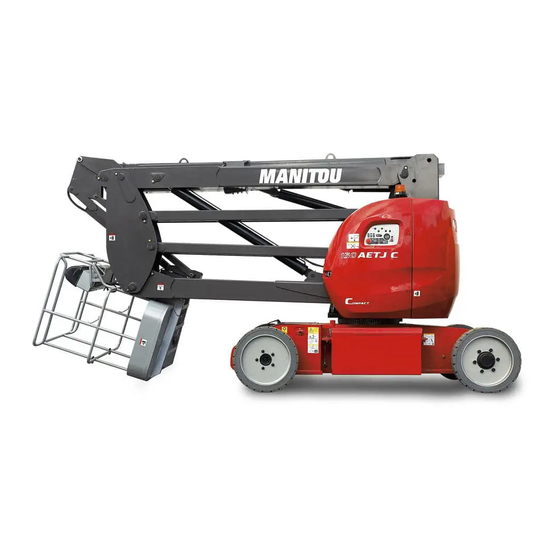
Manitou 120AETJL. No Drive when lifted the boom

1 comments:
Mr. Anderson
May 14, 2025

A Manitou AETJL 120 may have no drive when the boom is lifted due to the rear axle being in freewheel mode. This mode disengages the drive function, which can occur during maintenance or if activated unintentionally.

This answer is automatically generated

Subscribe to Our Youtube Channel

Summary of Contents for Manitou AETJL 120

  • Page 1 MANUEL DE RÉPARATION REPARATURANLEITUNG MANUAL DE REPARACIÓN MANUALE RIPARAZIONE This document has been printed from MANITOU BF Head office: 430, Rue de l’Aubinière 44150 Ancenis - FRANCE Share capital: 39,548,949 euros 857 802 508 RCS Nantes Tel: +33 (0)2 40 09 10 11...
  • Page 2 MANITOU BF. Any violation of the aforementioned may lead to civil and criminal prosecution. The logos as well as the visual identity of the company are the property of MANITOU BF and may not be used without express and formal authorization.
  • Page 3 COMPLET REPAIR MANUAL 120 AETJL 150 AETJC - AETJ 43150 AETJC 3D - AETJ 43 150 AETJL170 AETJL - AETJ 49 GENERAL INSTRUCTIONS AND SAFETY NOTICE GROUP 00 GENERAL CHARACTERISTICS AND SAFETY AXLE ASSEMBLY - AXLE GROUP 30 AXLE FRONT ARMS GROUP 55 JIB - BASKET HYDRAULIC GROUP 70 HYDRAULIC...
  • Page 4 547379EN (08/03/2017) 120 AETJL 150 AETJC - AETJ 43 150 AETJC 3D - AETJ 43 3D 150 AETJL 170 AETJL - AETJ 49 REPAIR MANUAL...
  • Page 5 MANITOU BF. Any violation of the aforementioned may lead to civil and criminal prosecution. The logos as well as the visual identity of the company are the property of MANITOU-BF...
  • Page 6 GENERAL CHARACTERISTICS AND SAFETY ENGINE TRANSMISSION AXLE BRAKE JIB - BASKET HYDRAULIC ELECTRICITY DRIVER’S CAB FRAME - BODY OPTIONS - ATTACHMENTS...
  • Page 7 547379EN (08/03/2017) INTERACTIVE REPAIR MANUAL...
  • Page 8 547379EN (08/03/2017) GLOSSARY Ammonia Oxidation Catalysts: elimination by oxidation of the excess ammonia (NH3) from exhaust gases having undergone selective catalytic reduction (SCR) of nitrogen oxides (NOx), by injection of ammonia. After Power Contact: post-ignition current. BMEP Bloc Manipulateur ÉlectroProportionnel : Controls the hydraulic movements of: lowering, lifting, tilting and digging by electronic sensors.
  • Page 9 547379EN (08/03/2017) 16 – The signal from the device is high (moderate severity) . 17 – The signal from the device is low (least severe) . 18 – The signal from the device is low (moderate severity) . 19 – There is an error in the data from the device. 20 –...
  • Page 10: Table Of Contents

    GENERAL CHARACTERISTICS AND SAFETY TABLE OF CONTENTS 00.1 GENERAL INSTRUCTIONS AND SAFETY NOTICE ..........8 00.1.1 INTRODUCTION .
  • Page 11: General Instructions And Safety Notice

    – Please follow all safety instructions. – Use the appropriate tools for any work to be performed. – Use original Manitou spare parts. Any non-compliance increases the risk of accidents occurring which may lead to causing grievous bodily harm and even death.
  • Page 12: Explanation Of Symbols

    At any time, as an operator, you must consider, within reason, the possible risk to yourself, to others or to the lift truck itself when you repair, service or drive it. Manitou cannot be held responsible for the use of any lifting devices, tools or operating methods other than those specifi ed.
  • Page 13: Servicing Rules

    547379EN GENERAL CHARACTERISTICS AND SAFETY 00 (08/03/2017) 00.1.4 SERVICING RULES Do not carry out any work on the machine unless you have followed a suitable training course and have the knowledge required for it. Make sure you have taken into consideration all the indicator plates on the machine and in the instruction manual.
  • Page 14 547379EN GENERAL CHARACTERISTICS AND SAFETY 00 (08/03/2017) AVERTISSEMENT Never step on a part of the machine that has not been designed for it. AVERTISSEMENT Never wear clothes, jewelry or objects that could get caught during work and cause accidents. Always wear protection glasses, gloves, safety shoes as well as any other protection required for the work to be carried out.
  • Page 15 547379EN GENERAL CHARACTERISTICS AND SAFETY 00 (08/03/2017) DANGER When lifting or shoring a component of the machine, make sure the equipment used is suitable for at least the load for which it is subjected by the component and that it meets the national standards for lifting devices. When using a jack, make sure it is used on a fl at, uniform surface, is sturdy enough to support the load, that its lifting capacity is suffi cient and that it is correctly placed and positioned under the machine.
  • Page 16: General Characteristics And Specifications

    (500 lbs) (500 lbs) 00.2.2 LUBRICANTS AND FUEL Designation Type Quantity 18 ℓ Hydraulic tank MANITOU ISO VG 46 Hydraulic oil (4.76 US gallons) 0.8 ℓ Wheel motor (each) (0.21 US gallons) SHELL SPIRAX A90 oil Turret rotation motor 1.5 ℓ...
  • Page 17: Dimensions

    547379EN GENERAL CHARACTERISTICS AND SAFETY 00 (08/03/2017) 00.2.3 DIMENSIONS DIMENSIONS 120AETJL ft-in 5520 18-1.3 3930 12-10.7 2000 6-6.7 1995 6-6.5 2210 7-3.0 1500 4-11.1 0-6.0 2640 8-8.0 1870 6-1.6 3960 12-11.9 4520 14-9.9...
  • Page 18 547379EN GENERAL CHARACTERISTICS AND SAFETY 00 (08/03/2017) ft-in ft-in 2350 7-8.5 9950 32-7.7 3105 10-2.2 8795 28-10.3 6370 20-10.8 4775 15-8.0 5640 18-6.0 1-9.5...
  • Page 19: Dimensions 150Aetjc - Aetj 43 - Aetjc 43 3D

    547379EN GENERAL CHARACTERISTICS AND SAFETY 00 (08/03/2017) DIMENSIONS 150AETJC - AETJ 43 - AETJC 43 3D ft-in 6050 19-10.2 4400 14-5.2 2000 6-6.7 1965 6-5.4 2080 6-9.9 1500 4-11.1 0-5.6 2640 8-7.9 1870 6-1.6 3960 12-11.9 4820 15-9.7...
  • Page 20 547379EN GENERAL CHARACTERISTICS AND SAFETY 00 (08/03/2017) ft-in ft-in 2665 8-8.9 12985 42-7.2 3425 11-2.8 11835 38-9.9 7105 23-3.7 7165 23-6.1 6300 20-8.0 0-9.2...
  • Page 21: Dimensions 150Aetjl

    547379EN GENERAL CHARACTERISTICS AND SAFETY 00 (08/03/2017) DIMENSIONS 150AETJL ft-in 5960 19-6.6 4400 14-5.2 2000 6-6.7 1970 6-5.5 2080 6-9.9 1750 5-8.9 0-5.6 2880 9-5.4 1970 6-5.6 4270 14-0.1 4890 16-0.5...
  • Page 22 547379EN GENERAL CHARACTERISTICS AND SAFETY 00 (08/03/2017) ft-in ft-in 2660 8-8.7 13275 43-6.6 3420 11-2.6 12120 39-9.1 7310 23-11.8 7165 23-6.1 6500 21-3.9 0-8.1...
  • Page 23: Dimensions 170Aetjl - 49 Aetjc

    547379EN GENERAL CHARACTERISTICS AND SAFETY 00 (08/03/2017) DIMENSIONS 170AETJL - 49 AETJC ft-in 6840 22-5.3 5120 16-9.6 2000 6-6.7 1970 6-5.6 2040 6-8.3 1750 5-8.9 0-5.5 2890 9-5.8 2005 6-6.9 4300 14-1.3 5600 18-4.5...
  • Page 24 547379EN GENERAL CHARACTERISTICS AND SAFETY 00 (08/03/2017) ft-in 2840 9-3.8 3600 11-9.7 8930 29-3.6 8130 26-8.1 14905 48-10.8 13750 45-1.3 7160 23-5.9 0-10.6                  ...
  • Page 25: Location Of Name And Identification Plate

    547379EN GENERAL CHARACTERISTICS AND SAFETY 00 (08/03/2017) GENERAL LOCATION 00.2.4 LOCATION OF NAME AND IDENTIFICATION PLATE As our policy is one of constant improvement of our products, our range of access platforms may undergo certain modifications, without obligation for us to advise our customers. When you order parts, or when you require any technical information, always specify: NOTE: For the owner's convenience, it is recommended that a note of these numbers is made in the spaces provided, at the time of the delivery of the access platform.
  • Page 26: General Control And Adjustment

    547379EN GENERAL CHARACTERISTICS AND SAFETY 00 (08/03/2017) 00.3 GENERAL CONTROL AND ADJUSTMENT 00.3.1 STANDARD TIGHTENING TORQUES STANDARD TIGHTENING TORQUES (N.m & lb-in)) Standard tightening torques To be used. unless otherwise indicated in the removal or refi t operations. SCREW / NUT ASSEMBLY - with hexagon head screws without fl anges ou cylinder head hexagon socket screws.
  • Page 27: Metric - Imperial Unit Conversion

    547379EN GENERAL CHARACTERISTICS AND SAFETY 00 (08/03/2017) 00.3.2 METRIC - IMPERIAL UNIT CONVERSION RULES -The tolerance has the same unit as the value and is not a percentage : Example : 120 ± 12 Ω , not 120 ± 10 %. -The unit is separated from the value by a space and placed after the tolerance : Example: 120 Ω...
  • Page 28 AXLE TABLE OF CONTENTS 30.1 CHARACTERISTICS AND SPECIFICATIONS ..........27 30.1.1 REAR AXLE - OPERATION IN FREEWHEEL MODE .
  • Page 29 547379EN AXLE 30 (08/03/2017)
  • Page 30 547379EN AXLE 30 (08/03/2017) AXLE 30.1 CHARACTERISTICS AND SPECIFICATIONS 30.1.1 REAR AXLE - OPERATION IN FREEWHEEL MODE DANGER In order to operate the access platform in freewheel mode, it should not be subjected to translational constraints resulting from a slope. When the access platform is in the freewheel mode, it can move freely: fit wedges to immobilize the wheels.
  • Page 32 JIB - BASKET TABLE OF CONTENTS 55.1 JIB - BASKET CONTROLS ..............31 55.1.1 CHECK THE CLEARANCE OF THE TELESCOPE .
  • Page 33 547379EN JIB - BASKET 55 (08/03/2017)
  • Page 34 547379EN JIB - BASKET 55 (08/03/2017) JIB - BASKET 55.1 JIB - BASKET CONTROLS 55.1.1 CHECK THE CLEARANCE OF THE TELESCOPE CLEARANCE between moving tube and arm of telescope Lateral 0.5 mm (0.02 in) Upper 0.5 mm (0.02 in) If necessary, add the adjustment plates if necessary (see parts catalogs). 55.2 JIB - BASKET REMOVAL 55.2.1 REMOVAL OF PADS OF TELESCOPIC CYLINDER Remove the telescopic cylinder (...
  • Page 35 547379EN JIB - BASKET 55 (08/03/2017) 55.2.3 REMOVAL OF PADS OF TELESCOPE MOVING TUBE - Remove the telescopic cylinder ( TELESCOPIC CYLINDER - REMOVAL, 55 - 8 - Remove the flexible guide fasteners on the moving tube (1 , 055 - 8 - Sling the basket/jib/hinge assembly (2 , 055 - 8 without steering actuator (3D - JIB) 230 kg (507 lbs)
  • Page 36 HYDRAULIC TABLE OF CONTENTS 70.1 HYDRAULIC SCHEMATIC DIAGRAMS ..........35 70.1.1 679449 - HYDRAULIC DIAGRAM.
  • Page 37 547379EN HYDRAULIC 70 (08/03/2017) LINKS TO REPAIR MANUALS: MANUAL REFERENCE DESIGNATION NUMBER 647 187 ROTARY ACTUATORS HELICAL HYDRAULIC L20 SERIE...
  • Page 38: Hydraulic Schematic Diagrams

    547379EN HYDRAULIC 70 (08/03/2017) HYDRAULIC 70.1 HYDRAULIC SCHEMATIC DIAGRAMS 70.1.1 679449 - HYDRAULIC DIAGRAM Brakes 3D - JIB Turret rotation rotation 25 b mini Compensation / Tilt 210 b Steering Arms 1/2 EV22 110b Basket EV23 150 b Arm 3 Telescope Pendular arm rotation...
  • Page 39 547379EN HYDRAULIC 70 (08/03/2017)
  • Page 40 547379EN HYDRAULIC 70 (08/03/2017) This diagram relates to lifting platforms : - 150 AETJC - 150 AETJC 3D - AETJ 43 - AETJ 43 3D - 150 AETJL ACTIVATION TABLE FOR THE ELECTRO-VALVES - 170 AETJL - AETJ 49 ACCORDING TO THE DESIRED MOVEMENT COMPONANTS OF THE HYDRAULIC LAYOUT Please refer to the hydraulic layout to match the electro-valve numbers and their location on the platform NOTE : Delivery of the block with the adjustment...
  • Page 41 547379EN HYDRAULIC 70 (08/03/2017)
  • Page 42: 685268 - Hydraulic Diagram

    547379EN HYDRAULIC 70 (08/03/2017) 70.1.2 685268 - HYDRAULIC DIAGRAM Compensation / Tilt Brakes 3D - JIB Turret rotation rotation 210 b Steering E V 22 Basket 25 b mini Arm 3 Telescope 150 b Pendular arm Arms 1/2 E V 23 rotation 220 b 110 b...
  • Page 43 547379EN HYDRAULIC 70 (08/03/2017)
  • Page 44 547379EN HYDRAULIC 70 (08/03/2017) This diagram relates to lifting platforms : - 150 AETJC - 150 AETJC 3D - AETJ 43 - AETJ 43 3D - 150 AETJL ACTIVATION TABLE FOR THE ELECTRO-VALVES - 170 AETJL - AETJ 49 ACCORDING TO THE DESIRED MOVEMENT COMPONANTS OF THE HYDRAULIC LAYOUT Please refer to the hydraulic layout to match the electro-valve numbers and their location on the platform NOTE : Delivery of the block with the adjustment...
  • Page 45 547379EN HYDRAULIC 70 (08/03/2017)
  • Page 46: Hydraulic Components Location

    547379EN HYDRAULIC 70 (08/03/2017) 70.2 HYDRAULIC COMPONENTS LOCATION 70.2.1 HYDRAULIC COMPONENTS OF THE CHASSIS - LOCATION Reducing gear/Brake of left wheel Steering cylinder Reducing gear/Brake of right wheel...
  • Page 47: Hydraulic Components Of The Turret - Location

    547379EN HYDRAULIC 70 (08/03/2017) 70.2.2 HYDRAULIC COMPONENTS OF THE TURRET - LOCATION Accumulator 150AETJC - 150 AETJC 3D - 150 AETJL - 170 AETJL AETJ 43 - AETJ 43 3D - AETJ 49 Oil tank Electric pump Backup pump Turret rotation engine Distributor block...
  • Page 48: Hydraulic Components Of The Jib - Location

    547379EN HYDRAULIC 70 (08/03/2017) 70.2.3 HYDRAULIC COMPONENTS OF THE JIB - LOCATION - 120 AETJL : Compensating cylinder Telescope cylinder Tilting cylinder Arm 3 lifting cylinder Jib cylinder Arm 1-2 lifting arm cylinder Basket rotation cylinder...
  • Page 49 547379EN HYDRAULIC 70 (08/03/2017) - 150 AETJC, 150 AETJC 3D, 150 AETJL, 170 AETJL, AETJ43, AETJ43 3D, AETJ 49 : Compensating cylinder Telescope cylinder Tilting cylinder 3D-JIB rotation cylinder Arm 3 lifting cylinder Jib cylinder A r m 1 - 2 l i f t i n g arm cylinder Basket rotation cylinder...
  • Page 50: Hydraulic Control And Adjustment

    547379EN HYDRAULIC 70 (08/03/2017) 70.3 HYDRAULIC CONTROL AND ADJUSTMENT CAUTION In this chapter, unless specifically indicated, in order to view the setting pressure values and choose the appropriate pressure gauge, refer to the hydraulic diagrams ( 70.1.1 679449 - HYDRAULIC DIAGRAM, + (6 5 35 70.1.2 685268 - HYDRAULIC DIAGRAM,...
  • Page 51: Brake Release Circuit - Pressure Setting

    547379EN HYDRAULIC 70 (08/03/2017) 70.3.3 BRAKE RELEASE CIRCUIT - PRESSURE SETTING CAUTION Procedure to be performed by two people. Use a pressure gauge with a capacity of 0 - 250 bar (0-3625.94 psi). The pressure switch is adjusted only by TIGHTENING the adjustment screw. PRESSURE SWITCH ADJUSTMENT 70 - 13 ),(19...
  • Page 52: Telescopic Circuit - Pressure Setting

    547379EN HYDRAULIC 70 (08/03/2017) 70.3.4 TELESCOPIC CIRCUIT - PRESSURE SETTING 70 - 16 PRESSURE REDUCER SETTING ), (18 70.1.1 70.1.2 - Decompress the telescopic line (distributor) ( 70.3.10 DISTRIBUTOR - REMOVAL, - Place a Tee connector on the by-pass at outlet A3 (1 ) and , 070 - 16 connect the pressure gauge (2...
  • Page 53: Compensation/Tilting Circuit - Pressure Setting

    547379EN HYDRAULIC 70 (08/03/2017) 70.3.5 COMPENSATION/TILTING CIRCUIT - PRESSURE SETTING 70 - 18 DECOMPRESSION OF THE CIRCUIT - Decompression of the compensation/ tilting circuit ( COMPENSATION/TILTING CYLINDER REMOVAL, - Switch off the power to the access platform. VALVE A ADJUSTMENT ), (19 70.1.1 70.1.2...
  • Page 54: Valve B Adjustment

    547379EN HYDRAULIC 70 (08/03/2017) 70 - 23 VALVE B ADJUSTMENT (18, ), (19 70.1.1 70.1.2 - Place a Tee connector on the by-pass at outlet B5 (1 ) and , 070 - 23 connect the pressure gauge (1 , 070 - 23 - Switch on the access platform.
  • Page 55: Compensation/Tilting Circuit - Problem Solving

    547379EN HYDRAULIC 70 (08/03/2017) 70.3.6 COMPENSATION/TILTING CIRCUIT - PROBLEM SOLVING - If the basket does not remain in position and drops under gravity 70 - 27 when the access platform is not in operation, perform the following test procedure. TEST PROCEDURE - Decompression of the compensation/tilting circuit ( 70.3.11 CYLINDERS - REMOVAL,...
  • Page 56: Analysis Of Results

    547379EN HYDRAULIC 70 (08/03/2017) ANALYSIS OF RESULTS - THE BASKET REMAINS IN POSITION AND THE HYDRAULIC PRESSURE HAS NOT DROPPED: the cylinder or the seals of the compensating cylinder are faulty. - Remove the compensation cylinder 70.3.11 CYLINDERS - REMOVAL, - Remove the cylinder and check the condition of the seals.
  • Page 57: Turret Rotation Motor - Removal

    547379EN HYDRAULIC 70 (08/03/2017) 70.3.7 TURRET ROTATION MOTOR - REMOVAL - Open the right-hand turret cover. 70 - 31 - Decompress the turret rotation line (distributor) ( 70.3.10 DISTRIBUTOR - REMOVAL, - Open the left-hand turret cover (1 , 070 - 31 - Remove and plug the two hoses (1 , 070 - 32 70 - 32...
  • Page 58: Electric Pump - Removal

    547379EN HYDRAULIC 70 (08/03/2017) 70.3.8 ELECTRIC PUMP - REMOVAL - Open the left-hand turret cover (1 , 070 - 33 70 - 33 Following fitting (see figure ), (see figure , 070 - 34 , 070 - 35 70 - 34 - Remove and plug the hose (1 ), (1 , 070 - 34...
  • Page 59: Reducing Gears/Wheel Brakes - Removal

    547379EN HYDRAULIC 70 (08/03/2017) 70.3.9 REDUCING GEARS/WHEEL BRAKES - REMOVAL - Raise the rear of the access platform and place blocks under the 70 - 36 frame (1 , 070 - 36 120 AETJL : 2680 kg (5908 lbs) 150 AETJC : 3770 kg (8311 lbs) 150 AETJL - 150 AETJC 3D : 3375 kg (7440 lbs) 170 AETJL - AETJ49 : 3842 kg (8470 lbs) AETJ43 - AETJ43 3D : 3775 kg (8323 lbs)
  • Page 60: Distributor - Removal

    547379EN HYDRAULIC 70 (08/03/2017) 70.3.10 DISTRIBUTOR - REMOVAL WARNING The hoses connected to the compensation/tilting cylinders are under pressure EVEN WHEN STOPPED. Before carrying out work to remove the distributor, these hoses must be decompressed by following the steps (I, 070 - 41), (II, 070 - 40) and (III, 070 - 42) because this line cannot be decompressed from the distributor.
  • Page 61 547379EN HYDRAULIC 70 (08/03/2017)
  • Page 62: Distributor - Details

    547379EN HYDRAULIC 70 (08/03/2017) DISTRIBUTOR - DETAILS A - 3D-JIB power According to supply Scoop installation lowering Telescope retracted Hydraulic Hydraulic Tightening torque P - Electric pump Item Designation diagram diagram in N.m (lb-in) 679449 685268 pressure Arm 3 Lowered Distributor Electrovalve Item 4...
  • Page 63: Cylinders - Removal

    547379EN HYDRAULIC 70 (08/03/2017) 70.3.11 CYLINDERS - REMOVAL STEERING CYLINDER - REMOVAL - Raise the front (1 ) of the access platform and place blocks , 070 - 44 70 - 44 under the frame: - 120 AETJL : 2400 kg (5291 lbs) - 150 AETJC : 3000 kg (6614 lbs) - 150 AETJL - 150 AETJC 3D : 2550 kg (5622 lbs) - 170 AETJL - AETJ49 : 3100 kg (6834 lbs)
  • Page 64: Arm 1/2 Lifting Cylinder - Removal

    547379EN HYDRAULIC 70 (08/03/2017) ARM 1/2 LIFTING CYLINDER - REMOVAL - Raise arm 1/2 so that the intermediate hinge (1 ) is raised , 070 - 46 70 - 46 1m (39.37 in). - Switch off the power supply. - Secure the intermediate hinge with a hoist and a sling (2 , 070 - 46 - 120 AETJL: 1100 kg (2425 lbs) - 150 AETJC - 150 AETJL - AETJ43 - AETJ 43 3D : 1600 kg (3527 lbs)
  • Page 65: Arm 3 Lifting Cylinder - Removal

    547379EN HYDRAULIC 70 (08/03/2017) ARM 3 LIFTING CYLINDER - REMOVAL - Raise the arm 1/2 so that the upper hinge (1 ) is raised by , 070 - 48 70 - 48 1m (39.37 in). - Switch off the power supply. - Secure the basket and arm 3 with a hoist (2 ) and a sling , 070 - 48...
  • Page 66: Telescopic Cylinder - Removal

    547379EN HYDRAULIC 70 (08/03/2017) TELESCOPIC CYLINDER - REMOVAL - Raise arm 3 to the horizontal position (1 , 070 - 50 70 - 50 - Move the telescope extension (2 ) by 1 m (39.37 in). , 070 - 50 - Remove the cylinder head pivot pin (3 , 070 - 50 - Retract the telescope.
  • Page 67: Compensation/Tilting Cylinder Removal

    547379EN HYDRAULIC 70 (08/03/2017) COMPENSATION/TILTING CYLINDER REMOVAL WARNING The hose connected to the compensation/tilting cylinders are pressurized EVEN WHEN STOPPED. Before carrying out work to remove the cylinders, these hoses must be decompressed by following the steps (I ), (II ) and (III ) because this line cannot be decompressed from the , 070 - 53...
  • Page 68 547379EN HYDRAULIC 70 (08/03/2017) 70 - 57 Tilting cylinder - Move the telescope extension by 1m (1 , 070 - 57 - Switch off the power supply. - Secure the basket/jib assembly with a hoist and a sling (2 , 070 - 57 without rotation cylinder (3D - JIB): 230 kg (507 lbs) 1 m (39.37 in) with rotation cylinder (3D - JIB): 267 kg (589 lbs)
  • Page 69: Jib Cylinder - Removal

    547379EN HYDRAULIC 70 (08/03/2017) JIB CYLINDER - REMOVAL - Lift the jib (1 ) to the horizontal position. , 070 - 63 70 - 63 - Switch off the power supply. - Secure the basket with a hoist and a sling (2 , 070 - 63 - 170 kg (375 lbs) - Place the assembly on a stable surface.
  • Page 70: Basket Rotation Cylinder - Removal

    547379EN HYDRAULIC 70 (08/03/2017) BASKET ROTATION CYLINDER - REMOVAL - Lift the jib (1 ) to the horizontal position. , 070 - 65 70 - 65 - Switch off the power supply. - Open the right-hand turret cover. 70 - 66 - Decompress the basket rotation line ( 70.3.10 DISTRIBUTOR - REMOVAL,...
  • Page 71: Rotation Cylinder (3D - Jib) - Removal

    547379EN HYDRAULIC 70 (08/03/2017) ROTATION CYLINDER (3D - JIB) - REMOVAL - Decompression of the tilting cylinder circuit ( COMPENSATION/ 70 - 67 TILTING CYLINDER REMOVAL, - Move the telescope extension by 1 m (39.37 in) - Switch off the power supply. - Open the right-hand turret cover.
  • Page 72 547379EN HYDRAULIC 70 (08/03/2017) VALVE BLOCKS AND VALVES - REMOVAL WARNING A cylinder fitted with valves may have chambers with VERY HIGH PRESSURES, higher than 100 bars (1450.38 psi) (tilting cylinder or cylinder with rod fully retracted or extended) even after being removed. The pressures in the chambers should be released before disassembly.
  • Page 73 547379EN HYDRAULIC 70 (08/03/2017)
  • Page 74 ELECTRICITY TABLE OF CONTENTS 80.1 ELECTRICAL SCHEMATIC DIAGRAMS............73 80.1.1 SCHEMATIC DIAGRAM - POWER PART - 1 VERSION .
  • Page 75 547379EN ELECTRICITY 80 (08/03/2017) 80.3.2 IES BATTERY CHARGER ..............106 IES BATTERY CHARGER REMOVAL.
  • Page 76: Electrical Schematic Diagrams

    547379EN ELECTRICITY 80 (08/03/2017) ELECTRICITY 80.1 ELECTRICAL SCHEMATIC DIAGRAMS WARNING Diagram 1 VERSION Access platform fitted with an overload sensor harness comprising: a Deutsch connector with............8-way S Q 5 a S Q 5 a S Q 5 b WARNING Diagram 2 VERSION Access platform fitted with an overload sensor harness comprising:...
  • Page 78: Schematic Diagram - Power Part

    547379EN ELECTRICITY 80 (08/03/2017) 80.1.1 SCHEMATIC DIAGRAM - POWER PART - 1 VERSION * Unless otherwise stated, the indicator lights and actuators hyave a nominal voltage of 24 V * CHARGER yellow white singles black Base control blue Platform control green Emergency stop...
  • Page 79: Schematic Diagram - Base Control Part

    547379EN ELECTRICITY 80 (08/03/2017) 80.1.2 SCHEMATIC DIAGRAM - BASE CONTROL PART - 1 VERSION * Unless otherwise stated, the indicator lights and actuators have a nominal voltage of 24V * CAN bus socket : Diagnostics Connection to the calibrator 678423 - Index MOLEX Mini-Fit box for male / 6 way contacts Page 2/4...
  • Page 80: Schematic Diagram - Basket Control Part

    547379EN ELECTRICITY 80 (08/03/2017) 80.1.3 SCHEMATIC DIAGRAM - BASKET CONTROL PART - 1 VERSION * Unless otherwise stated, the indicator lights and actuators have a nominal voltage of 24V * Overload arms pendular arm - Basket - Turret horn 678423 - Index R Page 3/4 Emergency stop horn...
  • Page 81: Schematic Diagram - Safety Control Unit Part

    547379EN ELECTRICITY 80 (08/03/2017) 80.1.4 SCHEMATIC DIAGRAM - SAFETY CONTROL UNIT PART - 1 VERSION * Unless otherwise stated, the indicator lights and actuators have a nominal voltage of 24V * Sector sensor control module 678423 - Index R Page 4/4 arm low B arm low A telescope retracted A...
  • Page 82: Schematic Diagram - Power Part

    547379EN ELECTRICITY 80 (08/03/2017) 80.1.5 SCHEMATIC DIAGRAM - POWER PART - 2 VERSION CHARGER supply yellow white 678423 - Index S B: Base control (singles LEDS) black Page 1/4 blue P: Platform control green Base Emergency Stop BASE/ GREEN BASKET Selector SLOPE black...
  • Page 83: Schematic Diagram - Basket Control Part

    547379EN ELECTRICITY 80 (08/03/2017) 80.1.6 SCHEMATIC DIAGRAM - BASKET CONTROL PART - 2 VERSION CAN bus socket : Diagnostics CAN-L : CAN-6 CAN-H : CAN-5 678423 - Index S B: Base control MOLEX Mini-Fit box +12V : CAN-4 P: Platform control 0V : CAN-2 for males/ 6 way contacts Page 2/4...
  • Page 84: Schematic Diagram - Safety Control Unit Part

    547379EN ELECTRICITY 80 (08/03/2017) 80.1.7 SCHEMATIC DIAGRAM - SAFETY CONTROL UNIT PART - 2 VERSION 1 - basket Overload arm 3 arms 1.2 2 - turret compensation pendular arm selection 3 - JIB horn selection selection selection 678423 - Index S Page 3/4 CAN6 : CAN-L CAN5 : CAN-H...
  • Page 85 547379EN ELECTRICITY 80 (08/03/2017) 80.1.8 SCHEMATIC DIAGRAM - SAFETY CONTROL UNIT PART - 2 VERSION Sector sensor control module 678423 - Index S Page 4/4 A5 : CAN-L A6 : CAN-H B02 : arm low B B01 : arm low A B03 : telescope retracted A B04 : telescope retracted B B05: overload SQ5b...
  • Page 86: Electrical Components Location

    547379EN ELECTRICITY 80 (08/03/2017) 80.2 ELECTRICAL COMPONENTS LOCATION 80.2.1 ELECTRICAL CONTROL COMPONENTS - LOCATION Rotating Retracted telescope Tilt sensor beacon light sensor Horn Base control panel Safety control card Arm down sensors 150 AETJC - 150 AETJC 3D - 150 AETJL - 170AETJL AETJ 43 - AETJ 43 3D - AETJ 49 Base module control unit Basket module control unit...
  • Page 87: Electrical Power Components - Location

    547379EN ELECTRICITY 80 (08/03/2017) 80.2.2 ELECTRICAL POWER COMPONENTS - LOCATION Electric pump Left-hand battery Safety control card Variable speed controller plate Right-hand battery Left traction motor Battery cut-off Variable speed controller plate relay IES charger Right traction motor ZIVAN charger...
  • Page 88: Wiring Based On Schematic Diagram 676423

    547379EN ELECTRICITY 80 (08/03/2017) 80.4.4 WIRING BASED ON SCHEMATIC DIAGRAM 676423 - 1 VERSION LOCATION OF WIRING HARNESSES ON THE ACCESS PLATFORM 120 AETJL Item Designation Basket control panel Upper CAN extension harness Lower CAN extension harness BUS-CAN harness output Base box Variable speed controller harness Electrovalve harness...
  • Page 89: Basket Control Panel Harness

    547379EN ELECTRICITY 80 (08/03/2017) BASKET CONTROL PANEL HARNESS - ITEM 1 Installation procedure: - 678383 - C (120 AETJL, 150 AETJC,150 AETJC 3D,150 AETJL,170 AETJL). 106 106 HD 30 8P PC CIRC IMP To overload To overload BASKET CONSOLE sensors harness sensors harness HARNESS Ref.
  • Page 90 547379EN ELECTRICITY 80 (08/03/2017) - ITEM 1 Installation procedure: - 52501871. (150 AETJC,150 AETJC 3D,150 AETJL,170 AETJL) - 52556918. (AETJ 43,AETJ 43 3D, AETJ 49) 123 4S 106 12P7 123 4S 103 8P 6 12P PC 4P PC 8P PC CIRC IMP To overload To upper BUS CAN...
  • Page 91 547379EN ELECTRICITY 80 (08/03/2017) Basket module control unit D-IN D-OUT D-NEG A-IN C-NEG B-NEG 103 according to installation Pos. Wire Pos. Wire Pos. Wire Pos. Wire spare spare spare spare spare spare spare spare spare spare spare spare spare spare spare spare spare...
  • Page 92: Overload Sensors Harness

    547379EN ELECTRICITY 80 (08/03/2017) OVERLOAD SENSORS HARNESS - ITEM 16 To full basket control panel Item 1 5 6 7 8 Wire Color black black/white brown OVERLOAD SENSORS blue HARNESS black 678849 - D black/white Item 16 free free SQ5a SQ5b...
  • Page 93: Upper Bus-Can Extension Harness

    547379EN ELECTRICITY 80 (08/03/2017) UPPER BUS-CAN EXTENSION HARNESS - ITEM 2 Installation procedure: 678855 - C (120 AETJL) 678387 - D (150 AETJC, 150 AETJC 3D,150 AETJL) 678643 - E (170 AETJL) To complete basket console Ref. 1 Pos. Wire Spare Spare 400 optional spare...
  • Page 94 547379EN ELECTRICITY 80 (08/03/2017) Installation procedure: 52501939.(150 AETJC, 150 AETJC 3D,150 AETJL, AETJ 43, AETJ 43 3D) 52501918. (170 AETJL, AETJ 49) To complete basket console Ref. 1 Pos. Wire Pos. Wire UPPER BUS CAN EXTENSION HARNESS 52501939 (150 AETJC - 150 AETC 3D - 150 AETJL - AETJ 43 - AETJ 43 3D) 52501918.
  • Page 95: Lower Bus-Can Extension Harness

    547379EN ELECTRICITY 80 (08/03/2017) LOWER BUS-CAN EXTENSION HARNESS - ITEM 3 To upper BUS CAN extension harness as mounting Ref. 2 5 6 7 8 5 6 7 8 Pos. Wire Pos. Wire LOWER BUS CAN EXTENSION BUNDLE 678863 - B (120 AETJL) 678388 - D (150 AETJ COMPACT - 150 AETJC 3D 150 AETJL - 170 AETJL AETJ 43 - AETJ 43 3D - AETJ 49)
  • Page 96: Upper Bus-Can Control Panel Output Harness

    547379EN ELECTRICITY 80 (08/03/2017) UPPER BUS-CAN CONTROL PANEL OUTPUT HARNESS - ITEM 4 To lower BUS CAN extension harness Ref. 3 Pos. Wire Pos. Wire BUS CAN CONSOLE OUTPUT HARNESS 678394 - C Ref. 4 To complete base box Rep. 5...
  • Page 97: Base Box Harness

    547379EN ELECTRICITY 80 (08/03/2017) BASE BOX HARNESS - ITEM 5 KA10 KA11 OUTPUT 241 241 TERMINAL 103 103 INPUT 241 241 103 103 BUS CAN console ensor console output harness output harness F3 + 24V F2 + 24V Ref. 4 Ref.
  • Page 98 547379EN ELECTRICITY 80 (08/03/2017) yellow yellow yellow H1 H2 H3 H4 137 F3 137 CAN BUS OUT2 OUT1 CAN SECU Wire Pos. spare Pos. Wire Wire Pos. spare spare spare spare Pos. Designation Pos. Designation spare Base module card Emergency Stop spare Security control card Base/basket selector...
  • Page 99: Variable Speed Controller Harness

    547379EN ELECTRICITY 80 (08/03/2017) VARIABLE SPEED CONTROLLER HARNESS - ITEM 6 VARIABLE SPEED Pos. Wire HARNESS variable speed drive spare drive board 678397 - C spare Ref. 6 spare Pos. Wire spare spare To charger Pos. Wire Colour brown Spare white Spare Spare...
  • Page 100: Electrovalve Harness

    547379EN ELECTRICITY 80 (08/03/2017) ELECTROVALVE HARNESS ELECTRO-VALVE HARNESS - ITEM 7 678393 - E Ref. 4 Pos. Wire Couleur Liaison 241 Bown EV6 - LOWER ARM UP 239 White D OUT 03 241 Bown EV8 - UPPER ARM UP 238 White D OUT 05 241 Bown EV10 - TELESC.
  • Page 101: Miscellaneous Harness

    547379EN ELECTRICITY 80 (08/03/2017) MISCELLANEOUS HARNESS - ITEMS 8, 9, 10, 11 Pos. Wire Colour Pink Dark Blue Black Wire Colour SENSORS CONSOLE OUTPUT Pink Violet Orange HARNESS Dark Blue 678476 - C Black To Arm low sensors bundle Ref. 11 (120 AETJL) - Ref.
  • Page 102 547379EN ELECTRICITY 80 (08/03/2017) MISCELLANEOUS HARNESS - ITEMS 12, 13, 14, 15 Installation procedure: - 120 AETJL SQ4a marron bleu noir CAPTEURS INDUCTIF 678901 - A Rep. 13 SQ4b FAISCEAU CAPTEURS FAISCEAU BRAS BAS CAPTEURS 678883 - B TELESCOPE Rep. 14 678864 - C Rep.
  • Page 103 547379EN ELECTRICITY 80 (08/03/2017) - ITEMS 12, 13, 14, 15 Installation procedure: - 150 AETJC - 150 AETJC 3D - 150 AETJL - 170 AETJL - AETJ 43 - AETJ 43 3D - AETJ 49 SQ4a marron bleu noir CAPTEURS INDUCTIF 678901 - A Rep.
  • Page 104: Electrical Control And Adjustment

    547379EN ELECTRICITY 80 (08/03/2017) 80.3 ELECTRICAL CONTROL AND ADJUSTMENT 80.3.1 ZIVAN BATTERY CHARGER ZIVAN BATTERY CHARGER REMOVAL - Raise the arm 1/2 so that the upper hinge (1, 080 - 72) is raised 80 - 72 by 1 m (39.37 in). -Turn the turret by 1/4 turn (2, 080 - 73) - Switch off the power supply.
  • Page 105: Zivan Battery Charger Description

    547379EN ELECTRICITY 80 (08/03/2017) ZIVAN BATTERY CHARGER DESCRIPTION EXTERNAL VIEW 80 - 74 - Mains power supply cable........(1, 080 - 74) - LED indicator ..........(2, 080 - 74) - Charging cables ............(3, 080 - 74) - Auxiliary contacts ........... (4, 080 - 74) - 5-pin plug............
  • Page 106: Zivan Battery Charger Connections

    547379EN ELECTRICITY 80 (08/03/2017) ZIVAN BATTERY CHARGER CONNECTIONS - Auxiliary contacts to cut-off load movements: internal diagram 80 - 76 (see figure, 080 - 76). AUX 1 AUX 2 - 5-pin plug to connection the removed LED harness: external 80 - 77 diagram (see figure, 080 - 77).
  • Page 107 547379EN ELECTRICITY 80 (08/03/2017) ZIVAN BATTERY CHARGER CONNECTIONS LOAD CURVES - Voltage curve: 80 - 78 - Amperage curve: STOP - Properties: Intensity: lm = 43 A I1 = 36 A I2 = 4% C5 Voltage: U1 = 57.6 V Um = 66 V Other: C = C5 Type of charger...
  • Page 108 547379EN ELECTRICITY 80 (08/03/2017) ZIVAN BATTERY CHARGER - INDICATORS LED charger indicator (see figure, 080 - 79) 80 - 79 - Red permanently on: initial charging phase. - Yellow permanently on: battery at 80% charge. 100% - Green permanently on: battery at 100% charge. - LED flashing + intermittent audible signal from the charger: alarm situation ( 80.5 TROUBLESHOOTING - ELECTRICAL,...
  • Page 109: Ies Battery Charger

    547379EN ELECTRICITY 80 (08/03/2017) 80.3.2 IES BATTERY CHARGER IES BATTERY CHARGER REMOVAL 80 - 81 - Raise the arm 1/2 so that the upper hinge (1, 080 - 81) is raised by 1 m (39.37 in). -Turn the turret by 1/4 turn (2, 080 - 81) - Switch off the power supply.
  • Page 110: Ies Battery Charger Description

    547379EN ELECTRICITY 80 (08/03/2017) IES BATTERY CHARGER DESCRIPTION EXTERNAL VIEW 80 - 83 - Charging cables ............(1, 080 - 83) - Mains power supply cable........(2, 080 - 83) - Auxiliary contacts ........... (3, 080 - 83) - 5-pin plug............ (4, 080 - 83) IES BATTERY CHARGER CONNECTIONS Auxiliary contacts to cut-off load movements: internal diagram 80 - 84...
  • Page 111: Ies Battery Charger Connections Load Curves

    547379EN ELECTRICITY 80 (08/03/2017) IES BATTERY CHARGER CONNECTIONS LOAD CURVES The charging current is selected automatically. IES BATTERY CHARGER - INDICATOR LED indicator removed (see figure, 080 - 86) 80 - 86 - Off: charger not powered - Red permanently on: initial charging phase. - Yellow permanently on: battery at 80% charge.
  • Page 112: Electronic Modules - Control And Settings

    547379EN ELECTRICITY 80 (08/03/2017) 80.3.3 ELECTRONIC MODULES - CONTROL AND SETTINGS ELECTRONIC CONTROL UNITS - REMOVAL Base module control unit + safety control card 80 - 87 - Open the right-hand turret cover (1, 080 - 87). - Open the front face of the base control panel (2, 080 - 87). - Remove the plate holding the card in place (1, 080 - 88) and 80 - 88 remove the cards:...
  • Page 113: Electronic Control Units Description And Wiring

    547379EN ELECTRICITY 80 (08/03/2017) ELECTRONIC CONTROL UNITS DESCRIPTION AND WIRING Base module control unit 80 - 90 80 - 91 C-NEG D-OUT A-IN D-IN 1 2 3 1 2 3 4 5 6 7 8 9 10 11 1 1 2 3 4 5 6 7 8 4 5 6 5 6 7 14 15 16 17 18 19 20 21 22 23...
  • Page 114 547379EN ELECTRICITY 80 (08/03/2017) Base module control unit Measure using the calibrator Multimeter Connector PIN Wire N° Signal Menu Description Not activated Activated Not activated Activated Tank return NOT MEASURABLE Arm 1/2 - Lowered NOT MEASURABLE Arm 1/2 - Raised NOT MEASURABLE Arm 3 Lowered NOT MEASURABLE...
  • Page 115 547379EN ELECTRICITY 80 (08/03/2017) Safety control card 80 - 93 80 - 92 OUT2 1 2 3 1 2 3 4 5 6 7 8 9 10 11 4 5 6 14 15 16 17 18 19 20 21 22 23 OUT1 LED RUN : ON, control unit powered.
  • Page 116 547379EN ELECTRICITY 80 (08/03/2017) Basket module control unit 80 - 95 80 - 94 A-IN D-IN D-OUT 1 2 3 4 5 6 5 6 7 LED RUN : - ON, control unit powered. - OFF, control unit switched off, defective or BUS-CAN problem. Base module control unit Measure using the calibrator Multimeter...
  • Page 117: Electronic Modules - Diagnostics And Settings

    547379EN ELECTRICITY 80 (08/03/2017) Base module control unit Measure using the calibrator Multimeter Connector PIN Wire N° Signal Menu Description Not activated Activated Not activated Activated Turret rotation NOT MEASURABLE Arm 1/2 NOT MEASURABLE Arm 3 NOT MEASURABLE Telescope NOT MEASURABLE NOT MEASURABLE JIB Rotation NOT MEASURABLE...
  • Page 118: Variable Speed Controllers - Control And Settings

    547379EN ELECTRICITY 80 (08/03/2017) 80.3.4 VARIABLE SPEED CONTROLLERS - CONTROL AND SETTINGS VARIABLE SPEED CONTROLLERS - DESCRIPTION Relay and fuse holder plate 80 - 96 - Power contacts: - Line contact KM1 (A1-1) - Resistance ..... 46.1 Ω - Electric pump KM3 (2, 080 - 96) - Resistance ..... 46.1 Ω - Traction/pump motors KM2 (3, 080 - 96) - Resistance .....
  • Page 119: Variable Speed Controllers - Wiring

    547379EN ELECTRICITY 80 (08/03/2017) VARIABLE SPEED CONTROLLERS - WIRING Control circuit - Electronic module 80 - 99 80 - 98 1 2 3 4 5 6 Base module control unit Measure using the calibrator Multimeter Connector PIN Wi r e N° Signal Type of signal Menu...
  • Page 120 547379EN ELECTRICITY 80 (08/03/2017) Power circuit 80 - 100 Variable speed controller plate Variable speed controller plate relay...
  • Page 121: Variable Speed Controllers - Diagnostic And Adjustment Tools

    547379EN ELECTRICITY 80 (08/03/2017) VARIABLE SPEED CONTROLLERS - DIAGNOSTIC AND ADJUSTMENT TOOLS CALIBRATOR CAUTION The calibrator is also used for: - The adjustment of the switches. ( 80.3.4 VARIABLE SPEED CONTROLLERS - CONTROL AND SETTINGS, - Testing the manipulators. ( 80.3.6 MANIPULATOR - OPERATION AND SETTINGS, - Troubleshooting.
  • Page 122: Battery Charge Indicator/Hour Meter

    547379EN ELECTRICITY 80 (08/03/2017) BATTERY CHARGE INDICATOR/HOUR METER Description 80 - 104 - Screen (1, 080 - 104). - Battery charge indicator (2, 080 - 104). - Hour meter and variable speed controller fault display screen (3, 100% 080 - 104). Maintenance SEVCON 80 - 105...
  • Page 123: Variable Speed Controllers - Use Of Calibrator

    547379EN ELECTRICITY 80 (08/03/2017) VARIABLE SPEED CONTROLLERS - USE OF CALIBRATOR Structure of electronic module menu - Configuration submenus: Black text on white background ( CONFIGURATION MENUS, - Test submenus: White text on black background ( TEST MENUS, SEVCON CAN CALIBRATOR MENU LEVELS Action Pump...
  • Page 124 547379EN ELECTRICITY 80 (08/03/2017) CONFIGURATION MENUS Mini Maxi Menu Traction Personalities Travel parameters Pitch Value display display 1.1.1A Armature I Max (A) Armature limit current (A) 1.1.1F Field I Max (A) Field limit current (A) 1.1.2 Traction Accel Delay (s) Acceleration curve (s) 1.1.3 Traction Decel Delay (s)
  • Page 125 547379EN ELECTRICITY 80 (08/03/2017) Menu Traction Motor Setup Motor setup Mini display Maxi display Pitch Value 1.7.1 Armature I Low (A) Armature low current (A) 1.7.2 Field I Low (A) Field low current (A) 1.7.3 Armature I Mid (A) Armature mid current (A) 1.7.4 Field I Mid (A) Field mid current (A)
  • Page 126 547379EN ELECTRICITY 80 (08/03/2017) Menu Pump Upper Box Pers Parameters Hydraulic Functions Average value Time target Basket codes 120AETJL 150AETL/C 170AETJL 120AETJL 150AETL/C 170AETJL 2.3.1 Boom 1 Up Speed (%) Lifting speed arm 1 & 2 2.3.2 Boom 1 Down Speed (%) Lowering speed arm 1 &...
  • Page 127 547379EN ELECTRICITY 80 (08/03/2017) TEST MENUS Menu Traction Status Status (Variable Speed Controller) Mini display Maxi display Pitch Log. Info 1.2.1 Battery Voltage Battery voltage 127 V 1.2.2 Armature Motor Voltage Armature Voltage 127 V 1.2.3 Field Motor Voltage Field voltage 127 V 1.2.4 Armature Motor Current...
  • Page 128 547379EN ELECTRICITY 80 (08/03/2017) Menu Pump Upper Box Test Test Hydraulic Functions Basket Codes Mini display Maxi display Pitch Type 2.4.1 Y axis Joystick % Joystick - Y-axis % 0.01 range 2.4.2 Y axis Joystick Voltage Joystick - Y-Axis Voltage 0.0 V 5.0 V 0.02 V...
  • Page 129: Safety Components - Control And Settings

    547379EN ELECTRICITY 80 (08/03/2017) 80.3.5 SAFETY COMPONENTS - CONTROL AND SETTINGS SWITCHES - LOCATION 80.2.2 ELECTRICAL POWER COMPONENTS - LOCATION, TILT SENSOR - SETTINGS CAUTION The tilt sensors are pre-configured by the manufacturer. The only parameter that can be adjusted is sensor initialization. - Place the access platform on level ground and leave the power 80 - 106 switched on.
  • Page 130: Arm Down Sensors - Settings

    547379EN ELECTRICITY 80 (08/03/2017) ARM DOWN SENSORS - SETTINGS -- Set the telescope to the down position, ensuring the control is 120 AETJL 80 - 108 activated for as long as necessary, keeping the access platform switched on. ACCESS PLATFORM 120 AETJL - Loosen the lock nuts (1, 080 - 108).
  • Page 131: Brake Release Circuit - Checking

    547379EN ELECTRICITY 80 (08/03/2017) BRAKE RELEASE CIRCUIT - CHECKING CAUTION The configuration of the pressure switch (1, 080 - 111) is hydraulic and not electrical ( 70.3.3 BRAKE RELEASE CIRCUIT - PRESSURE SETTING, This chapter does not deal with verification of the signals. 80 - 111 Checking Pressure switch SQ3...
  • Page 132: Overload Sensors - Settings

    547379EN ELECTRICITY 80 (08/03/2017) OVERLOAD SENSORS - SETTINGS 80 - 112 PROCEDURE - Set the basket to the low position, keeping the access platform switched on. - Remove the cover (1, 080 - 112). - Connect the calibrator to the access platform ( 80.3.4 VARIABLE SPEED CONTROLLERS - CONTROL AND SETTINGS, Overload spring pre-tensioning adjustment...
  • Page 133 547379EN ELECTRICITY 80 (08/03/2017) Overload test - Of the load still in the basket, take out 20 kg (44 lbs) and check that: - The alarm switches off. - The calibrator displays CLOSED in test menu 1.3.16 (SQ5a). - The calibrator displays OPEN in test menu 2.4.9 (SQ5b). - Replace the 20 kg (44 lbs), the alarm triggers (permanent tone), tighten the lock nuts (1, 080 - 113) and put a paint mark on them to confirm the configuration.
  • Page 134 547379EN ELECTRICITY 80 (08/03/2017) SIMPLIFIED OVERLOAD WIRING DIAGRAM Module Controle capt. sec. Part N° 662/13124 Réf. CI678453 A5 : CAN-L A6 : CAN-H B02 : bras_bas_SQ1b B01 : bras_bas_SQ1a B03 : tel_rentré_SQ4a B04 : tel_rentré_SQ4b B05 : surcharge SQ5b B06 : surcharge SQ5a B07 : retour réduction vitesse B06 : retour validation surcharge Out_2 : retour vitesse...
  • Page 135: Multimeter Test

    547379EN ELECTRICITY 80 (08/03/2017) OVERLOAD SIGNAL - The reference of the overload signal is emitted by the basket card, output Do 18 (wire 335)....(680.1 ELECTRICAL SCHEMATIC DIAGRAMS, 5 73) U(V) Multimeter reading 0.6V t(s) Calibrator OPEN OPEN reading CLOSED CLOSED MULTIMETER TEST Overload sensor SQ5a...
  • Page 136: Manipulator - Operation And Settings

    547379EN ELECTRICITY 80 (08/03/2017) 80.3.6 MANIPULATOR - OPERATION AND SETTINGS MANIPULATOR - TESTS USING CALIBRATOR CAUTION The manipulator test from the basket base requires the presence of two operators. - Connect the calibrator to the access platform and display test menu 2-4 ( 80.3.4 VARIABLE SPEED CONTROLLERS - CONTROL AND 80 - 114...
  • Page 137: Manipulator - Test With A Voltmeter

    547379EN ELECTRICITY 80 (08/03/2017) MANIPULATOR - TEST WITH A VOLTMETER 80 - 115 - Climb into the access platform with a voltmeter. - Remove the front face from the basket control panel (1, 080 - 115) and replace it. - Locate the colored wires at the manipulator connector (see figure, 080 - 116).
  • Page 138 547379EN ELECTRICITY 80 (08/03/2017) Testing the logic outputs - Press the top left-hand button followed by the top right-hand button (3, 080 - 114) without activating the trigger, and check the values displayed by the voltmeter (see figure, 080 - 118). 80 - 118 ANCIENNE NOUVELLE...
  • Page 139: Electricity Removals - Refitting

    547379EN ELECTRICITY 80 (08/03/2017) 80.4 ELECTRICITY REMOVALS - REFITTING 80.4.1 VARIABLE SPEED CONTROLLERS - REMOVAL 80 - 120 - Raise arm 1/2 so that the upper hinge (1, 080 - 120) is raised by 1 m (39.37 in). -Turn the turret by 1/4 turn (2, 080 - 120). - Switch off the power supply.
  • Page 140: Batteries - Removal

    547379EN ELECTRICITY 80 (08/03/2017) 80.4.2 BATTERIES - REMOVAL 80 - 123 - Disconnect the right-hand battery: - Remove the right-hand battery protective cover (1, 080 - 123). - Disconnect the - earth (2, 080 - 123). - Disconnect the + (3, 080 - 123). - Disconnect the left-hand battery, following the same procedure.
  • Page 141: Electrical Harnesses - Removal

    547379EN ELECTRICITY 80 (08/03/2017) 80.4.3 ELECTRICAL HARNESSES - REMOVAL A - Wiring based on the schematic diagrams ( 80.1.3 SCHEMATIC DIAGRAM - BASKET CONTROL PART - 1ST VERSION, CAUTION In this chapter, all of the connectors are shown on the wire insertion side.
  • Page 142: Troubleshooting - Electrical

    547379EN ELECTRICITY 80 (08/03/2017) 80.5 TROUBLESHOOTING - ELECTRICAL 80.5.1 VARIABLE SPEED CONTROLLERS - FAULTS AND FIXES Message Message Description and Investigations Variable Speed Hour meter Calibrator Comments Controller Traction operational and OK. No action required. F05003 Internal Fault Variable speed controller Variable speed controller needs replacing.
  • Page 143 547379EN ELECTRICITY 80 (08/03/2017) Message Message Description and Investigations Variable Speed Hour meter Calibrator Comments Controller 3 Flashs F05009 PUp Trac MOS Failure of power test when - Check the following points: switching on. • With the line switch (KM1) CLOSED, the voltage at terminal “A” of MOSFET the variable speed controller must be equal to the battery voltage (if no movement activated).
  • Page 144 547379EN ELECTRICITY 80 (08/03/2017) Message Message Description and Investigations Variable Speed Hour meter Calibrator Comments Controller 5 Flashs C_OVL Ssr Flt This fault is detected when there is - Check: a fault on the overload sensors. • The status of the overload circuits. FAULTS •...
  • Page 145 547379EN ELECTRICITY 80 (08/03/2017) Message Message Description and Investigations Variable Speed Hour meter Calibrator Comments Controller 12 Flashs F05005 Can Bus Fault There is no dialog between one or - Check for each of the electronic control units if their LED is CANBUS more electronic control units.
  • Page 146: Zivan Battery Charger - Error Signals

    547379EN ELECTRICITY 80 (08/03/2017) 80.5.2 ZIVAN BATTERY CHARGER - ERROR SIGNALS SYMPTOMS CAUSES TO BE DONE IMMEDIATELY CAUSES TO CHECK Output fuse and if the battery has Acoustic signal + Battery disconnected or not Check the connection or the rated been connected with the correct RED LED flashing compliant.
  • Page 147: Specific Tooling - Electricity

    547379EN ELECTRICITY 80 (08/03/2017) 80.6 SPECIFIC TOOLING - ELECTRICITY 80.6.1 CALIBRATOR CAUTION The calibrator is also used for: - The adjustment of the switches. 80.3.4 VARIABLE SPEED CONTROLLERS - CONTROL AND SETTINGS, - Testing the manipulators. 80.3.6 MANIPULATOR - OPERATION AND SETTINGS, - Troubleshooting.
  • Page 148 GENERAL CHARACTERISTICS AND SAFETY TABLE OF CONTENTS 00.1 GENERAL INSTRUCTIONS AND SAFETY NOTICE ..........8 00.1.1 INTRODUCTION .
  • Page 149: General Instructions And Safety Notice

    – Please follow all safety instructions. – Use the appropriate tools for any work to be performed. – Use original Manitou spare parts. Any non-compliance increases the risk of accidents occurring which may lead to causing grievous bodily harm and even death.
  • Page 150: Explanation Of Symbols

    At any time, as an operator, you must consider, within reason, the possible risk to yourself, to others or to the lift truck itself when you repair, service or drive it. Manitou cannot be held responsible for the use of any lifting devices, tools or operating methods other than those specifi ed.
  • Page 151: Servicing Rules

    547379EN GENERAL CHARACTERISTICS AND SAFETY 00 (08/03/2017) 00.1.4 SERVICING RULES Do not carry out any work on the machine unless you have followed a suitable training course and have the knowledge required for it. Make sure you have taken into consideration all the indicator plates on the machine and in the instruction manual.
  • Page 152 547379EN GENERAL CHARACTERISTICS AND SAFETY 00 (08/03/2017) AVERTISSEMENT Never step on a part of the machine that has not been designed for it. AVERTISSEMENT Never wear clothes, jewelry or objects that could get caught during work and cause accidents. Always wear protection glasses, gloves, safety shoes as well as any other protection required for the work to be carried out.
  • Page 153 547379EN GENERAL CHARACTERISTICS AND SAFETY 00 (08/03/2017) DANGER When lifting or shoring a component of the machine, make sure the equipment used is suitable for at least the load for which it is subjected by the component and that it meets the national standards for lifting devices. When using a jack, make sure it is used on a fl at, uniform surface, is sturdy enough to support the load, that its lifting capacity is suffi cient and that it is correctly placed and positioned under the machine.
  • Page 154: General Characteristics And Specifications

    (500 lbs) (500 lbs) 00.2.2 LUBRICANTS AND FUEL Designation Type Quantity 18 ℓ Hydraulic tank MANITOU ISO VG 46 Hydraulic oil (4.76 US gallons) 0.8 ℓ Wheel motor (each) (0.21 US gallons) SHELL SPIRAX A90 oil Turret rotation motor 1.5 ℓ...
  • Page 155: Dimensions

    547379EN GENERAL CHARACTERISTICS AND SAFETY 00 (08/03/2017) 00.2.3 DIMENSIONS DIMENSIONS 120AETJL ft-in 5520 18-1.3 3930 12-10.7 2000 6-6.7 1995 6-6.5 2210 7-3.0 1500 4-11.1 0-6.0 2640 8-8.0 1870 6-1.6 3960 12-11.9 4520 14-9.9...
  • Page 156 547379EN GENERAL CHARACTERISTICS AND SAFETY 00 (08/03/2017) ft-in ft-in 2350 7-8.5 9950 32-7.7 3105 10-2.2 8795 28-10.3 6370 20-10.8 4775 15-8.0 5640 18-6.0 1-9.5...
  • Page 157: Dimensions 150Aetjc - Aetj 43 - Aetjc 43 3D

    547379EN GENERAL CHARACTERISTICS AND SAFETY 00 (08/03/2017) DIMENSIONS 150AETJC - AETJ 43 - AETJC 43 3D ft-in 6050 19-10.2 4400 14-5.2 2000 6-6.7 1965 6-5.4 2080 6-9.9 1500 4-11.1 0-5.6 2640 8-7.9 1870 6-1.6 3960 12-11.9 4820 15-9.7...
  • Page 158 547379EN GENERAL CHARACTERISTICS AND SAFETY 00 (08/03/2017) ft-in ft-in 2665 8-8.9 12985 42-7.2 3425 11-2.8 11835 38-9.9 7105 23-3.7 7165 23-6.1 6300 20-8.0 0-9.2...
  • Page 159: Dimensions 150Aetjl

    547379EN GENERAL CHARACTERISTICS AND SAFETY 00 (08/03/2017) DIMENSIONS 150AETJL ft-in 5960 19-6.6 4400 14-5.2 2000 6-6.7 1970 6-5.5 2080 6-9.9 1750 5-8.9 0-5.6 2880 9-5.4 1970 6-5.6 4270 14-0.1 4890 16-0.5...
  • Page 160 547379EN GENERAL CHARACTERISTICS AND SAFETY 00 (08/03/2017) ft-in ft-in 2660 8-8.7 13275 43-6.6 3420 11-2.6 12120 39-9.1 7310 23-11.8 7165 23-6.1 6500 21-3.9 0-8.1...
  • Page 161: Dimensions 170Aetjl - 49 Aetjc

    547379EN GENERAL CHARACTERISTICS AND SAFETY 00 (08/03/2017) DIMENSIONS 170AETJL - 49 AETJC ft-in 6840 22-5.3 5120 16-9.6 2000 6-6.7 1970 6-5.6 2040 6-8.3 1750 5-8.9 0-5.5 2890 9-5.8 2005 6-6.9 4300 14-1.3 5600 18-4.5...
  • Page 162 547379EN GENERAL CHARACTERISTICS AND SAFETY 00 (08/03/2017) ft-in 2840 9-3.8 3600 11-9.7 8930 29-3.6 8130 26-8.1 14905 48-10.8 13750 45-1.3 7160 23-5.9 0-10.6                  ...
  • Page 163: Location Of Name And Identification Plate

    547379EN GENERAL CHARACTERISTICS AND SAFETY 00 (08/03/2017) GENERAL LOCATION 00.2.4 LOCATION OF NAME AND IDENTIFICATION PLATE As our policy is one of constant improvement of our products, our range of access platforms may undergo certain modifications, without obligation for us to advise our customers. When you order parts, or when you require any technical information, always specify: NOTE: For the owner's convenience, it is recommended that a note of these numbers is made in the spaces provided, at the time of the delivery of the access platform.
  • Page 164: General Control And Adjustment

    547379EN GENERAL CHARACTERISTICS AND SAFETY 00 (08/03/2017) 00.3 GENERAL CONTROL AND ADJUSTMENT 00.3.1 STANDARD TIGHTENING TORQUES STANDARD TIGHTENING TORQUES (N.m & lb-in)) Standard tightening torques To be used. unless otherwise indicated in the removal or refi t operations. SCREW / NUT ASSEMBLY - with hexagon head screws without fl anges ou cylinder head hexagon socket screws.
  • Page 165: Metric - Imperial Unit Conversion

    547379EN GENERAL CHARACTERISTICS AND SAFETY 00 (08/03/2017) 00.3.2 METRIC - IMPERIAL UNIT CONVERSION RULES -The tolerance has the same unit as the value and is not a percentage : Example : 120 ± 12 Ω , not 120 ± 10 %. -The unit is separated from the value by a space and placed after the tolerance : Example: 120 Ω...
  • Page 166 AXLE TABLE OF CONTENTS 30.1 CHARACTERISTICS AND SPECIFICATIONS ..........27 30.1.1 REAR AXLE - OPERATION IN FREEWHEEL MODE .
  • Page 167 547379EN AXLE 30 (08/03/2017)
  • Page 168 547379EN AXLE 30 (08/03/2017) AXLE 30.1 CHARACTERISTICS AND SPECIFICATIONS 30.1.1 REAR AXLE - OPERATION IN FREEWHEEL MODE DANGER In order to operate the access platform in freewheel mode, it should not be subjected to translational constraints resulting from a slope. When the access platform is in the freewheel mode, it can move freely: fit wedges to immobilize the wheels.
  • Page 170 JIB - BASKET TABLE OF CONTENTS 55.1 JIB - BASKET CONTROLS ..............31 55.1.1 CHECK THE CLEARANCE OF THE TELESCOPE .
  • Page 171 547379EN JIB - BASKET 55 (08/03/2017)
  • Page 172 547379EN JIB - BASKET 55 (08/03/2017) JIB - BASKET 55.1 JIB - BASKET CONTROLS 55.1.1 CHECK THE CLEARANCE OF THE TELESCOPE CLEARANCE between moving tube and arm of telescope Lateral 0.5 mm (0.02 in) Upper 0.5 mm (0.02 in) If necessary, add the adjustment plates if necessary (see parts catalogs). 55.2 JIB - BASKET REMOVAL 55.2.1 REMOVAL OF PADS OF TELESCOPIC CYLINDER Remove the telescopic cylinder (...
  • Page 173 547379EN JIB - BASKET 55 (08/03/2017) 55.2.3 REMOVAL OF PADS OF TELESCOPE MOVING TUBE - Remove the telescopic cylinder ( TELESCOPIC CYLINDER - REMOVAL, 55 - 8 - Remove the flexible guide fasteners on the moving tube (1 , 055 - 8 - Sling the basket/jib/hinge assembly (2 , 055 - 8 without steering actuator (3D - JIB) 230 kg (507 lbs)
  • Page 174 HYDRAULIC TABLE OF CONTENTS 70.1 HYDRAULIC SCHEMATIC DIAGRAMS ..........35 70.1.1 679449 - HYDRAULIC DIAGRAM.
  • Page 175 547379EN HYDRAULIC 70 (08/03/2017) LINKS TO REPAIR MANUALS: MANUAL REFERENCE DESIGNATION NUMBER 647 187 ROTARY ACTUATORS HELICAL HYDRAULIC L20 SERIE...
  • Page 176: Hydraulic Schematic Diagrams

    547379EN HYDRAULIC 70 (08/03/2017) HYDRAULIC 70.1 HYDRAULIC SCHEMATIC DIAGRAMS 70.1.1 679449 - HYDRAULIC DIAGRAM Brakes 3D - JIB Turret rotation rotation 25 b mini Compensation / Tilt 210 b Steering Arms 1/2 EV22 110b Basket EV23 150 b Arm 3 Telescope Pendular arm rotation...
  • Page 177 547379EN HYDRAULIC 70 (08/03/2017)
  • Page 178 547379EN HYDRAULIC 70 (08/03/2017) This diagram relates to lifting platforms : - 150 AETJC - 150 AETJC 3D - AETJ 43 - AETJ 43 3D - 150 AETJL ACTIVATION TABLE FOR THE ELECTRO-VALVES - 170 AETJL - AETJ 49 ACCORDING TO THE DESIRED MOVEMENT COMPONANTS OF THE HYDRAULIC LAYOUT Please refer to the hydraulic layout to match the electro-valve numbers and their location on the platform NOTE : Delivery of the block with the adjustment...
  • Page 179 547379EN HYDRAULIC 70 (08/03/2017)
  • Page 180: 685268 - Hydraulic Diagram

    547379EN HYDRAULIC 70 (08/03/2017) 70.1.2 685268 - HYDRAULIC DIAGRAM Compensation / Tilt Brakes 3D - JIB Turret rotation rotation 210 b Steering E V 22 Basket 25 b mini Arm 3 Telescope 150 b Pendular arm Arms 1/2 E V 23 rotation 220 b 110 b...
  • Page 181 547379EN HYDRAULIC 70 (08/03/2017)
  • Page 182 547379EN HYDRAULIC 70 (08/03/2017) This diagram relates to lifting platforms : - 150 AETJC - 150 AETJC 3D - AETJ 43 - AETJ 43 3D - 150 AETJL ACTIVATION TABLE FOR THE ELECTRO-VALVES - 170 AETJL - AETJ 49 ACCORDING TO THE DESIRED MOVEMENT COMPONANTS OF THE HYDRAULIC LAYOUT Please refer to the hydraulic layout to match the electro-valve numbers and their location on the platform NOTE : Delivery of the block with the adjustment...
  • Page 183 547379EN HYDRAULIC 70 (08/03/2017)
  • Page 184: Hydraulic Components Location

    547379EN HYDRAULIC 70 (08/03/2017) 70.2 HYDRAULIC COMPONENTS LOCATION 70.2.1 HYDRAULIC COMPONENTS OF THE CHASSIS - LOCATION Reducing gear/Brake of left wheel Steering cylinder Reducing gear/Brake of right wheel...
  • Page 185: Hydraulic Components Of The Turret - Location

    547379EN HYDRAULIC 70 (08/03/2017) 70.2.2 HYDRAULIC COMPONENTS OF THE TURRET - LOCATION Accumulator 150AETJC - 150 AETJC 3D - 150 AETJL - 170 AETJL AETJ 43 - AETJ 43 3D - AETJ 49 Oil tank Electric pump Backup pump Turret rotation engine Distributor block...
  • Page 186: Hydraulic Components Of The Jib - Location

    547379EN HYDRAULIC 70 (08/03/2017) 70.2.3 HYDRAULIC COMPONENTS OF THE JIB - LOCATION - 120 AETJL : Compensating cylinder Telescope cylinder Tilting cylinder Arm 3 lifting cylinder Jib cylinder Arm 1-2 lifting arm cylinder Basket rotation cylinder...
  • Page 187 547379EN HYDRAULIC 70 (08/03/2017) - 150 AETJC, 150 AETJC 3D, 150 AETJL, 170 AETJL, AETJ43, AETJ43 3D, AETJ 49 : Compensating cylinder Telescope cylinder Tilting cylinder 3D-JIB rotation cylinder Arm 3 lifting cylinder Jib cylinder A r m 1 - 2 l i f t i n g arm cylinder Basket rotation cylinder...
  • Page 188: Hydraulic Control And Adjustment

    547379EN HYDRAULIC 70 (08/03/2017) 70.3 HYDRAULIC CONTROL AND ADJUSTMENT CAUTION In this chapter, unless specifically indicated, in order to view the setting pressure values and choose the appropriate pressure gauge, refer to the hydraulic diagrams ( 70.1.1 679449 - HYDRAULIC DIAGRAM, + (6 5 35 70.1.2 685268 - HYDRAULIC DIAGRAM,...
  • Page 189: Brake Release Circuit - Pressure Setting

    547379EN HYDRAULIC 70 (08/03/2017) 70.3.3 BRAKE RELEASE CIRCUIT - PRESSURE SETTING CAUTION Procedure to be performed by two people. Use a pressure gauge with a capacity of 0 - 250 bar (0-3625.94 psi). The pressure switch is adjusted only by TIGHTENING the adjustment screw. PRESSURE SWITCH ADJUSTMENT 70 - 13 ),(19...
  • Page 190: Telescopic Circuit - Pressure Setting

    547379EN HYDRAULIC 70 (08/03/2017) 70.3.4 TELESCOPIC CIRCUIT - PRESSURE SETTING 70 - 16 PRESSURE REDUCER SETTING ), (18 70.1.1 70.1.2 - Decompress the telescopic line (distributor) ( 70.3.10 DISTRIBUTOR - REMOVAL, - Place a Tee connector on the by-pass at outlet A3 (1 ) and , 070 - 16 connect the pressure gauge (2...
  • Page 191: Compensation/Tilting Circuit - Pressure Setting

    547379EN HYDRAULIC 70 (08/03/2017) 70.3.5 COMPENSATION/TILTING CIRCUIT - PRESSURE SETTING 70 - 18 DECOMPRESSION OF THE CIRCUIT - Decompression of the compensation/ tilting circuit ( COMPENSATION/TILTING CYLINDER REMOVAL, - Switch off the power to the access platform. VALVE A ADJUSTMENT ), (19 70.1.1 70.1.2...
  • Page 192: Valve B Adjustment

    547379EN HYDRAULIC 70 (08/03/2017) 70 - 23 VALVE B ADJUSTMENT (18, ), (19 70.1.1 70.1.2 - Place a Tee connector on the by-pass at outlet B5 (1 ) and , 070 - 23 connect the pressure gauge (1 , 070 - 23 - Switch on the access platform.
  • Page 193: Compensation/Tilting Circuit - Problem Solving

    547379EN HYDRAULIC 70 (08/03/2017) 70.3.6 COMPENSATION/TILTING CIRCUIT - PROBLEM SOLVING - If the basket does not remain in position and drops under gravity 70 - 27 when the access platform is not in operation, perform the following test procedure. TEST PROCEDURE - Decompression of the compensation/tilting circuit ( 70.3.11 CYLINDERS - REMOVAL,...
  • Page 194: Analysis Of Results

    547379EN HYDRAULIC 70 (08/03/2017) ANALYSIS OF RESULTS - THE BASKET REMAINS IN POSITION AND THE HYDRAULIC PRESSURE HAS NOT DROPPED: the cylinder or the seals of the compensating cylinder are faulty. - Remove the compensation cylinder 70.3.11 CYLINDERS - REMOVAL, - Remove the cylinder and check the condition of the seals.
  • Page 195: Turret Rotation Motor - Removal

    547379EN HYDRAULIC 70 (08/03/2017) 70.3.7 TURRET ROTATION MOTOR - REMOVAL - Open the right-hand turret cover. 70 - 31 - Decompress the turret rotation line (distributor) ( 70.3.10 DISTRIBUTOR - REMOVAL, - Open the left-hand turret cover (1 , 070 - 31 - Remove and plug the two hoses (1 , 070 - 32 70 - 32...
  • Page 196: Electric Pump - Removal

    547379EN HYDRAULIC 70 (08/03/2017) 70.3.8 ELECTRIC PUMP - REMOVAL - Open the left-hand turret cover (1 , 070 - 33 70 - 33 Following fitting (see figure ), (see figure , 070 - 34 , 070 - 35 70 - 34 - Remove and plug the hose (1 ), (1 , 070 - 34...
  • Page 197: Reducing Gears/Wheel Brakes - Removal

    547379EN HYDRAULIC 70 (08/03/2017) 70.3.9 REDUCING GEARS/WHEEL BRAKES - REMOVAL - Raise the rear of the access platform and place blocks under the 70 - 36 frame (1 , 070 - 36 120 AETJL : 2680 kg (5908 lbs) 150 AETJC : 3770 kg (8311 lbs) 150 AETJL - 150 AETJC 3D : 3375 kg (7440 lbs) 170 AETJL - AETJ49 : 3842 kg (8470 lbs) AETJ43 - AETJ43 3D : 3775 kg (8323 lbs)
  • Page 198: Distributor - Removal

    547379EN HYDRAULIC 70 (08/03/2017) 70.3.10 DISTRIBUTOR - REMOVAL WARNING The hoses connected to the compensation/tilting cylinders are under pressure EVEN WHEN STOPPED. Before carrying out work to remove the distributor, these hoses must be decompressed by following the steps (I, 070 - 41), (II, 070 - 40) and (III, 070 - 42) because this line cannot be decompressed from the distributor.
  • Page 199 547379EN HYDRAULIC 70 (08/03/2017)
  • Page 200: Distributor - Details

    547379EN HYDRAULIC 70 (08/03/2017) DISTRIBUTOR - DETAILS A - 3D-JIB power According to supply Scoop installation lowering Telescope retracted Hydraulic Hydraulic Tightening torque P - Electric pump Item Designation diagram diagram in N.m (lb-in) 679449 685268 pressure Arm 3 Lowered Distributor Electrovalve Item 4...
  • Page 201: Cylinders - Removal

    547379EN HYDRAULIC 70 (08/03/2017) 70.3.11 CYLINDERS - REMOVAL STEERING CYLINDER - REMOVAL - Raise the front (1 ) of the access platform and place blocks , 070 - 44 70 - 44 under the frame: - 120 AETJL : 2400 kg (5291 lbs) - 150 AETJC : 3000 kg (6614 lbs) - 150 AETJL - 150 AETJC 3D : 2550 kg (5622 lbs) - 170 AETJL - AETJ49 : 3100 kg (6834 lbs)
  • Page 202: Arm 1/2 Lifting Cylinder - Removal

    547379EN HYDRAULIC 70 (08/03/2017) ARM 1/2 LIFTING CYLINDER - REMOVAL - Raise arm 1/2 so that the intermediate hinge (1 ) is raised , 070 - 46 70 - 46 1m (39.37 in). - Switch off the power supply. - Secure the intermediate hinge with a hoist and a sling (2 , 070 - 46 - 120 AETJL: 1100 kg (2425 lbs) - 150 AETJC - 150 AETJL - AETJ43 - AETJ 43 3D : 1600 kg (3527 lbs)
  • Page 203: Arm 3 Lifting Cylinder - Removal

    547379EN HYDRAULIC 70 (08/03/2017) ARM 3 LIFTING CYLINDER - REMOVAL - Raise the arm 1/2 so that the upper hinge (1 ) is raised by , 070 - 48 70 - 48 1m (39.37 in). - Switch off the power supply. - Secure the basket and arm 3 with a hoist (2 ) and a sling , 070 - 48...
  • Page 204: Telescopic Cylinder - Removal

    547379EN HYDRAULIC 70 (08/03/2017) TELESCOPIC CYLINDER - REMOVAL - Raise arm 3 to the horizontal position (1 , 070 - 50 70 - 50 - Move the telescope extension (2 ) by 1 m (39.37 in). , 070 - 50 - Remove the cylinder head pivot pin (3 , 070 - 50 - Retract the telescope.
  • Page 205: Compensation/Tilting Cylinder Removal

    547379EN HYDRAULIC 70 (08/03/2017) COMPENSATION/TILTING CYLINDER REMOVAL WARNING The hose connected to the compensation/tilting cylinders are pressurized EVEN WHEN STOPPED. Before carrying out work to remove the cylinders, these hoses must be decompressed by following the steps (I ), (II ) and (III ) because this line cannot be decompressed from the , 070 - 53...
  • Page 206 547379EN HYDRAULIC 70 (08/03/2017) 70 - 57 Tilting cylinder - Move the telescope extension by 1m (1 , 070 - 57 - Switch off the power supply. - Secure the basket/jib assembly with a hoist and a sling (2 , 070 - 57 without rotation cylinder (3D - JIB): 230 kg (507 lbs) 1 m (39.37 in) with rotation cylinder (3D - JIB): 267 kg (589 lbs)
  • Page 207: Jib Cylinder - Removal

    547379EN HYDRAULIC 70 (08/03/2017) JIB CYLINDER - REMOVAL - Lift the jib (1 ) to the horizontal position. , 070 - 63 70 - 63 - Switch off the power supply. - Secure the basket with a hoist and a sling (2 , 070 - 63 - 170 kg (375 lbs) - Place the assembly on a stable surface.
  • Page 208: Basket Rotation Cylinder - Removal

    547379EN HYDRAULIC 70 (08/03/2017) BASKET ROTATION CYLINDER - REMOVAL - Lift the jib (1 ) to the horizontal position. , 070 - 65 70 - 65 - Switch off the power supply. - Open the right-hand turret cover. 70 - 66 - Decompress the basket rotation line ( 70.3.10 DISTRIBUTOR - REMOVAL,...
  • Page 209: Rotation Cylinder (3D - Jib) - Removal

    547379EN HYDRAULIC 70 (08/03/2017) ROTATION CYLINDER (3D - JIB) - REMOVAL - Decompression of the tilting cylinder circuit ( COMPENSATION/ 70 - 67 TILTING CYLINDER REMOVAL, - Move the telescope extension by 1 m (39.37 in) - Switch off the power supply. - Open the right-hand turret cover.
  • Page 210 547379EN HYDRAULIC 70 (08/03/2017) VALVE BLOCKS AND VALVES - REMOVAL WARNING A cylinder fitted with valves may have chambers with VERY HIGH PRESSURES, higher than 100 bars (1450.38 psi) (tilting cylinder or cylinder with rod fully retracted or extended) even after being removed. The pressures in the chambers should be released before disassembly.
  • Page 211 547379EN HYDRAULIC 70 (08/03/2017)
  • Page 212 ELECTRICITY TABLE OF CONTENTS 80.1 ELECTRICAL SCHEMATIC DIAGRAMS............73 80.1.1 SCHEMATIC DIAGRAM - POWER PART - 1 VERSION .
  • Page 213 547379EN ELECTRICITY 80 (08/03/2017) 80.3.2 IES BATTERY CHARGER ..............106 IES BATTERY CHARGER REMOVAL.
  • Page 214: Electrical Schematic Diagrams

    547379EN ELECTRICITY 80 (08/03/2017) ELECTRICITY 80.1 ELECTRICAL SCHEMATIC DIAGRAMS WARNING Diagram 1 VERSION Access platform fitted with an overload sensor harness comprising: a Deutsch connector with............8-way S Q 5 a S Q 5 a S Q 5 b WARNING Diagram 2 VERSION Access platform fitted with an overload sensor harness comprising:...
  • Page 216: Schematic Diagram - Power Part

    547379EN ELECTRICITY 80 (08/03/2017) 80.1.1 SCHEMATIC DIAGRAM - POWER PART - 1 VERSION * Unless otherwise stated, the indicator lights and actuators hyave a nominal voltage of 24 V * CHARGER yellow white singles black Base control blue Platform control green Emergency stop...
  • Page 217: Schematic Diagram - Base Control Part

    547379EN ELECTRICITY 80 (08/03/2017) 80.1.2 SCHEMATIC DIAGRAM - BASE CONTROL PART - 1 VERSION * Unless otherwise stated, the indicator lights and actuators have a nominal voltage of 24V * CAN bus socket : Diagnostics Connection to the calibrator 678423 - Index MOLEX Mini-Fit box for male / 6 way contacts Page 2/4...
  • Page 218: Schematic Diagram - Basket Control Part

    547379EN ELECTRICITY 80 (08/03/2017) 80.1.3 SCHEMATIC DIAGRAM - BASKET CONTROL PART - 1 VERSION * Unless otherwise stated, the indicator lights and actuators have a nominal voltage of 24V * Overload arms pendular arm - Basket - Turret horn 678423 - Index R Page 3/4 Emergency stop horn...
  • Page 219: Schematic Diagram - Safety Control Unit Part

    547379EN ELECTRICITY 80 (08/03/2017) 80.1.4 SCHEMATIC DIAGRAM - SAFETY CONTROL UNIT PART - 1 VERSION * Unless otherwise stated, the indicator lights and actuators have a nominal voltage of 24V * Sector sensor control module 678423 - Index R Page 4/4 arm low B arm low A telescope retracted A...
  • Page 220 547379EN ELECTRICITY 80 (08/03/2017) 80.1.5 SCHEMATIC DIAGRAM - POWER PART - 2 VERSION CHARGER supply yellow white 678423 - Index S B: Base control (singles LEDS) black Page 1/4 blue P: Platform control green Base Emergency Stop BASE/ GREEN BASKET Selector SLOPE black...
  • Page 221 547379EN ELECTRICITY 80 (08/03/2017) 80.1.6 SCHEMATIC DIAGRAM - BASKET CONTROL PART - 2 VERSION CAN bus socket : Diagnostics CAN-L : CAN-6 CAN-H : CAN-5 678423 - Index S B: Base control MOLEX Mini-Fit box +12V : CAN-4 P: Platform control 0V : CAN-2 for males/ 6 way contacts Page 2/4...
  • Page 222 547379EN ELECTRICITY 80 (08/03/2017) 80.1.7 SCHEMATIC DIAGRAM - SAFETY CONTROL UNIT PART - 2 VERSION 1 - basket Overload arm 3 arms 1.2 2 - turret compensation pendular arm selection 3 - JIB horn selection selection selection 678423 - Index S Page 3/4 CAN6 : CAN-L CAN5 : CAN-H...
  • Page 223: Schematic Diagram - Safety Control Unit Part

    547379EN ELECTRICITY 80 (08/03/2017) 80.1.8 SCHEMATIC DIAGRAM - SAFETY CONTROL UNIT PART - 2 VERSION Sector sensor control module 678423 - Index S Page 4/4 A5 : CAN-L A6 : CAN-H B02 : arm low B B01 : arm low A B03 : telescope retracted A B04 : telescope retracted B B05: overload SQ5b...
  • Page 224: Electrical Components Location

    547379EN ELECTRICITY 80 (08/03/2017) 80.2 ELECTRICAL COMPONENTS LOCATION 80.2.1 ELECTRICAL CONTROL COMPONENTS - LOCATION Rotating Retracted telescope Tilt sensor beacon light sensor Horn Base control panel Safety control card Arm down sensors 150 AETJC - 150 AETJC 3D - 150 AETJL - 170AETJL AETJ 43 - AETJ 43 3D - AETJ 49 Base module control unit Basket module control unit...
  • Page 225: Electrical Power Components - Location

    547379EN ELECTRICITY 80 (08/03/2017) 80.2.2 ELECTRICAL POWER COMPONENTS - LOCATION Electric pump Left-hand battery Safety control card Variable speed controller plate Right-hand battery Left traction motor Battery cut-off Variable speed controller plate relay IES charger Right traction motor ZIVAN charger...
  • Page 226: Wiring Based On Schematic Diagram 676423

    547379EN ELECTRICITY 80 (08/03/2017) 80.4.4 WIRING BASED ON SCHEMATIC DIAGRAM 676423 - 1 VERSION LOCATION OF WIRING HARNESSES ON THE ACCESS PLATFORM 120 AETJL Item Designation Basket control panel Upper CAN extension harness Lower CAN extension harness BUS-CAN harness output Base box Variable speed controller harness Electrovalve harness...
  • Page 227: Basket Control Panel Harness

    547379EN ELECTRICITY 80 (08/03/2017) BASKET CONTROL PANEL HARNESS - ITEM 1 Installation procedure: - 678383 - C (120 AETJL, 150 AETJC,150 AETJC 3D,150 AETJL,170 AETJL). 106 106 HD 30 8P PC CIRC IMP To overload To overload BASKET CONSOLE sensors harness sensors harness HARNESS Ref.
  • Page 228 547379EN ELECTRICITY 80 (08/03/2017) - ITEM 1 Installation procedure: - 52501871. (150 AETJC,150 AETJC 3D,150 AETJL,170 AETJL) - 52556918. (AETJ 43,AETJ 43 3D, AETJ 49) 123 4S 106 12P7 123 4S 103 8P 6 12P PC 4P PC 8P PC CIRC IMP To overload To upper BUS CAN...
  • Page 229 547379EN ELECTRICITY 80 (08/03/2017) Basket module control unit D-IN D-OUT D-NEG A-IN C-NEG B-NEG 103 according to installation Pos. Wire Pos. Wire Pos. Wire Pos. Wire spare spare spare spare spare spare spare spare spare spare spare spare spare spare spare spare spare...
  • Page 230: Overload Sensors Harness

    547379EN ELECTRICITY 80 (08/03/2017) OVERLOAD SENSORS HARNESS - ITEM 16 To full basket control panel Item 1 5 6 7 8 Wire Color black black/white brown OVERLOAD SENSORS blue HARNESS black 678849 - D black/white Item 16 free free SQ5a SQ5b...
  • Page 231: Upper Bus-Can Extension Harness

    547379EN ELECTRICITY 80 (08/03/2017) UPPER BUS-CAN EXTENSION HARNESS - ITEM 2 Installation procedure: 678855 - C (120 AETJL) 678387 - D (150 AETJC, 150 AETJC 3D,150 AETJL) 678643 - E (170 AETJL) To complete basket console Ref. 1 Pos. Wire Spare Spare 400 optional spare...
  • Page 232 547379EN ELECTRICITY 80 (08/03/2017) Installation procedure: 52501939.(150 AETJC, 150 AETJC 3D,150 AETJL, AETJ 43, AETJ 43 3D) 52501918. (170 AETJL, AETJ 49) To complete basket console Ref. 1 Pos. Wire Pos. Wire UPPER BUS CAN EXTENSION HARNESS 52501939 (150 AETJC - 150 AETC 3D - 150 AETJL - AETJ 43 - AETJ 43 3D) 52501918.
  • Page 233: Lower Bus-Can Extension Harness

    547379EN ELECTRICITY 80 (08/03/2017) LOWER BUS-CAN EXTENSION HARNESS - ITEM 3 To upper BUS CAN extension harness as mounting Ref. 2 5 6 7 8 5 6 7 8 Pos. Wire Pos. Wire LOWER BUS CAN EXTENSION BUNDLE 678863 - B (120 AETJL) 678388 - D (150 AETJ COMPACT - 150 AETJC 3D 150 AETJL - 170 AETJL AETJ 43 - AETJ 43 3D - AETJ 49)
  • Page 234: Upper Bus-Can Control Panel Output Harness

    547379EN ELECTRICITY 80 (08/03/2017) UPPER BUS-CAN CONTROL PANEL OUTPUT HARNESS - ITEM 4 To lower BUS CAN extension harness Ref. 3 Pos. Wire Pos. Wire BUS CAN CONSOLE OUTPUT HARNESS 678394 - C Ref. 4 To complete base box Rep. 5...
  • Page 235: Base Box Harness

    547379EN ELECTRICITY 80 (08/03/2017) BASE BOX HARNESS - ITEM 5 KA10 KA11 OUTPUT 241 241 TERMINAL 103 103 INPUT 241 241 103 103 BUS CAN console ensor console output harness output harness F3 + 24V F2 + 24V Ref. 4 Ref.
  • Page 236 547379EN ELECTRICITY 80 (08/03/2017) yellow yellow yellow H1 H2 H3 H4 137 F3 137 CAN BUS OUT2 OUT1 CAN SECU Wire Pos. spare Pos. Wire Wire Pos. spare spare spare spare Pos. Designation Pos. Designation spare Base module card Emergency Stop spare Security control card Base/basket selector...
  • Page 237: Variable Speed Controller Harness

    547379EN ELECTRICITY 80 (08/03/2017) VARIABLE SPEED CONTROLLER HARNESS - ITEM 6 VARIABLE SPEED Pos. Wire HARNESS variable speed drive spare drive board 678397 - C spare Ref. 6 spare Pos. Wire spare spare To charger Pos. Wire Colour brown Spare white Spare Spare...
  • Page 238: Electrovalve Harness

    547379EN ELECTRICITY 80 (08/03/2017) ELECTROVALVE HARNESS ELECTRO-VALVE HARNESS - ITEM 7 678393 - E Ref. 4 Pos. Wire Couleur Liaison 241 Bown EV6 - LOWER ARM UP 239 White D OUT 03 241 Bown EV8 - UPPER ARM UP 238 White D OUT 05 241 Bown EV10 - TELESC.
  • Page 239: Miscellaneous Harness

    547379EN ELECTRICITY 80 (08/03/2017) MISCELLANEOUS HARNESS - ITEMS 8, 9, 10, 11 Pos. Wire Colour Pink Dark Blue Black Wire Colour SENSORS CONSOLE OUTPUT Pink Violet Orange HARNESS Dark Blue 678476 - C Black To Arm low sensors bundle Ref. 11 (120 AETJL) - Ref.
  • Page 240 547379EN ELECTRICITY 80 (08/03/2017) MISCELLANEOUS HARNESS - ITEMS 12, 13, 14, 15 Installation procedure: - 120 AETJL SQ4a marron bleu noir CAPTEURS INDUCTIF 678901 - A Rep. 13 SQ4b FAISCEAU CAPTEURS FAISCEAU BRAS BAS CAPTEURS 678883 - B TELESCOPE Rep. 14 678864 - C Rep.
  • Page 241 547379EN ELECTRICITY 80 (08/03/2017) - ITEMS 12, 13, 14, 15 Installation procedure: - 150 AETJC - 150 AETJC 3D - 150 AETJL - 170 AETJL - AETJ 43 - AETJ 43 3D - AETJ 49 SQ4a marron bleu noir CAPTEURS INDUCTIF 678901 - A Rep.
  • Page 242: Electrical Control And Adjustment

    547379EN ELECTRICITY 80 (08/03/2017) 80.3 ELECTRICAL CONTROL AND ADJUSTMENT 80.3.1 ZIVAN BATTERY CHARGER ZIVAN BATTERY CHARGER REMOVAL - Raise the arm 1/2 so that the upper hinge (1, 080 - 72) is raised 80 - 72 by 1 m (39.37 in). -Turn the turret by 1/4 turn (2, 080 - 73) - Switch off the power supply.
  • Page 243: Zivan Battery Charger Description

    547379EN ELECTRICITY 80 (08/03/2017) ZIVAN BATTERY CHARGER DESCRIPTION EXTERNAL VIEW 80 - 74 - Mains power supply cable........(1, 080 - 74) - LED indicator ..........(2, 080 - 74) - Charging cables ............(3, 080 - 74) - Auxiliary contacts ........... (4, 080 - 74) - 5-pin plug............
  • Page 244: Zivan Battery Charger Connections

    547379EN ELECTRICITY 80 (08/03/2017) ZIVAN BATTERY CHARGER CONNECTIONS - Auxiliary contacts to cut-off load movements: internal diagram 80 - 76 (see figure, 080 - 76). AUX 1 AUX 2 - 5-pin plug to connection the removed LED harness: external 80 - 77 diagram (see figure, 080 - 77).
  • Page 245: Zivan Battery Charger Connections Load Curves

    547379EN ELECTRICITY 80 (08/03/2017) ZIVAN BATTERY CHARGER CONNECTIONS LOAD CURVES - Voltage curve: 80 - 78 - Amperage curve: STOP - Properties: Intensity: lm = 43 A I1 = 36 A I2 = 4% C5 Voltage: U1 = 57.6 V Um = 66 V Other: C = C5 Type of charger...
  • Page 246 547379EN ELECTRICITY 80 (08/03/2017) ZIVAN BATTERY CHARGER - INDICATORS LED charger indicator (see figure, 080 - 79) 80 - 79 - Red permanently on: initial charging phase. - Yellow permanently on: battery at 80% charge. 100% - Green permanently on: battery at 100% charge. - LED flashing + intermittent audible signal from the charger: alarm situation ( 80.5 TROUBLESHOOTING - ELECTRICAL,...
  • Page 247: Ies Battery Charger

    547379EN ELECTRICITY 80 (08/03/2017) 80.3.2 IES BATTERY CHARGER IES BATTERY CHARGER REMOVAL 80 - 81 - Raise the arm 1/2 so that the upper hinge (1, 080 - 81) is raised by 1 m (39.37 in). -Turn the turret by 1/4 turn (2, 080 - 81) - Switch off the power supply.
  • Page 248: Ies Battery Charger Description

    547379EN ELECTRICITY 80 (08/03/2017) IES BATTERY CHARGER DESCRIPTION EXTERNAL VIEW 80 - 83 - Charging cables ............(1, 080 - 83) - Mains power supply cable........(2, 080 - 83) - Auxiliary contacts ........... (3, 080 - 83) - 5-pin plug............ (4, 080 - 83) IES BATTERY CHARGER CONNECTIONS Auxiliary contacts to cut-off load movements: internal diagram 80 - 84...
  • Page 249: Ies Battery Charger Connections Load Curves

    547379EN ELECTRICITY 80 (08/03/2017) IES BATTERY CHARGER CONNECTIONS LOAD CURVES The charging current is selected automatically. IES BATTERY CHARGER - INDICATOR LED indicator removed (see figure, 080 - 86) 80 - 86 - Off: charger not powered - Red permanently on: initial charging phase. - Yellow permanently on: battery at 80% charge.
  • Page 250: Electronic Modules - Control And Settings

    547379EN ELECTRICITY 80 (08/03/2017) 80.3.3 ELECTRONIC MODULES - CONTROL AND SETTINGS ELECTRONIC CONTROL UNITS - REMOVAL Base module control unit + safety control card 80 - 87 - Open the right-hand turret cover (1, 080 - 87). - Open the front face of the base control panel (2, 080 - 87). - Remove the plate holding the card in place (1, 080 - 88) and 80 - 88 remove the cards:...
  • Page 251: Electronic Control Units Description And Wiring

    547379EN ELECTRICITY 80 (08/03/2017) ELECTRONIC CONTROL UNITS DESCRIPTION AND WIRING Base module control unit 80 - 90 80 - 91 C-NEG D-OUT A-IN D-IN 1 2 3 1 2 3 4 5 6 7 8 9 10 11 1 1 2 3 4 5 6 7 8 4 5 6 5 6 7 14 15 16 17 18 19 20 21 22 23...
  • Page 252 547379EN ELECTRICITY 80 (08/03/2017) Base module control unit Measure using the calibrator Multimeter Connector PIN Wire N° Signal Menu Description Not activated Activated Not activated Activated Tank return NOT MEASURABLE Arm 1/2 - Lowered NOT MEASURABLE Arm 1/2 - Raised NOT MEASURABLE Arm 3 Lowered NOT MEASURABLE...
  • Page 253 547379EN ELECTRICITY 80 (08/03/2017) Safety control card 80 - 93 80 - 92 OUT2 1 2 3 1 2 3 4 5 6 7 8 9 10 11 4 5 6 14 15 16 17 18 19 20 21 22 23 OUT1 LED RUN : ON, control unit powered.
  • Page 254 547379EN ELECTRICITY 80 (08/03/2017) Basket module control unit 80 - 95 80 - 94 A-IN D-IN D-OUT 1 2 3 4 5 6 5 6 7 LED RUN : - ON, control unit powered. - OFF, control unit switched off, defective or BUS-CAN problem. Base module control unit Measure using the calibrator Multimeter...
  • Page 255: Electronic Modules - Diagnostics And Settings

    547379EN ELECTRICITY 80 (08/03/2017) Base module control unit Measure using the calibrator Multimeter Connector PIN Wire N° Signal Menu Description Not activated Activated Not activated Activated Turret rotation NOT MEASURABLE Arm 1/2 NOT MEASURABLE Arm 3 NOT MEASURABLE Telescope NOT MEASURABLE NOT MEASURABLE JIB Rotation NOT MEASURABLE...
  • Page 256: Variable Speed Controllers - Control And Settings

    547379EN ELECTRICITY 80 (08/03/2017) 80.3.4 VARIABLE SPEED CONTROLLERS - CONTROL AND SETTINGS VARIABLE SPEED CONTROLLERS - DESCRIPTION Relay and fuse holder plate 80 - 96 - Power contacts: - Line contact KM1 (A1-1) - Resistance ..... 46.1 Ω - Electric pump KM3 (2, 080 - 96) - Resistance ..... 46.1 Ω - Traction/pump motors KM2 (3, 080 - 96) - Resistance .....
  • Page 257: Variable Speed Controllers - Wiring

    547379EN ELECTRICITY 80 (08/03/2017) VARIABLE SPEED CONTROLLERS - WIRING Control circuit - Electronic module 80 - 99 80 - 98 1 2 3 4 5 6 Base module control unit Measure using the calibrator Multimeter Connector PIN Wi r e N° Signal Type of signal Menu...
  • Page 258 547379EN ELECTRICITY 80 (08/03/2017) Power circuit 80 - 100 Variable speed controller plate Variable speed controller plate relay...
  • Page 259: Variable Speed Controllers - Diagnostic And Adjustment Tools

    547379EN ELECTRICITY 80 (08/03/2017) VARIABLE SPEED CONTROLLERS - DIAGNOSTIC AND ADJUSTMENT TOOLS CALIBRATOR CAUTION The calibrator is also used for: - The adjustment of the switches. ( 80.3.4 VARIABLE SPEED CONTROLLERS - CONTROL AND SETTINGS, - Testing the manipulators. ( 80.3.6 MANIPULATOR - OPERATION AND SETTINGS, - Troubleshooting.
  • Page 260: Battery Charge Indicator/Hour Meter

    547379EN ELECTRICITY 80 (08/03/2017) BATTERY CHARGE INDICATOR/HOUR METER Description 80 - 104 - Screen (1, 080 - 104). - Battery charge indicator (2, 080 - 104). - Hour meter and variable speed controller fault display screen (3, 100% 080 - 104). Maintenance SEVCON 80 - 105...
  • Page 261: Variable Speed Controllers - Use Of Calibrator

    547379EN ELECTRICITY 80 (08/03/2017) VARIABLE SPEED CONTROLLERS - USE OF CALIBRATOR Structure of electronic module menu - Configuration submenus: Black text on white background ( CONFIGURATION MENUS, - Test submenus: White text on black background ( TEST MENUS, SEVCON CAN CALIBRATOR MENU LEVELS Action Pump...
  • Page 262 547379EN ELECTRICITY 80 (08/03/2017) CONFIGURATION MENUS Mini Maxi Menu Traction Personalities Travel parameters Pitch Value display display 1.1.1A Armature I Max (A) Armature limit current (A) 1.1.1F Field I Max (A) Field limit current (A) 1.1.2 Traction Accel Delay (s) Acceleration curve (s) 1.1.3 Traction Decel Delay (s)
  • Page 263 547379EN ELECTRICITY 80 (08/03/2017) Menu Traction Motor Setup Motor setup Mini display Maxi display Pitch Value 1.7.1 Armature I Low (A) Armature low current (A) 1.7.2 Field I Low (A) Field low current (A) 1.7.3 Armature I Mid (A) Armature mid current (A) 1.7.4 Field I Mid (A) Field mid current (A)
  • Page 264 547379EN ELECTRICITY 80 (08/03/2017) Menu Pump Upper Box Pers Parameters Hydraulic Functions Average value Time target Basket codes 120AETJL 150AETL/C 170AETJL 120AETJL 150AETL/C 170AETJL 2.3.1 Boom 1 Up Speed (%) Lifting speed arm 1 & 2 2.3.2 Boom 1 Down Speed (%) Lowering speed arm 1 &...
  • Page 265 547379EN ELECTRICITY 80 (08/03/2017) TEST MENUS Menu Traction Status Status (Variable Speed Controller) Mini display Maxi display Pitch Log. Info 1.2.1 Battery Voltage Battery voltage 127 V 1.2.2 Armature Motor Voltage Armature Voltage 127 V 1.2.3 Field Motor Voltage Field voltage 127 V 1.2.4 Armature Motor Current...
  • Page 266 547379EN ELECTRICITY 80 (08/03/2017) Menu Pump Upper Box Test Test Hydraulic Functions Basket Codes Mini display Maxi display Pitch Type 2.4.1 Y axis Joystick % Joystick - Y-axis % 0.01 range 2.4.2 Y axis Joystick Voltage Joystick - Y-Axis Voltage 0.0 V 5.0 V 0.02 V...
  • Page 267: Safety Components - Control And Settings

    547379EN ELECTRICITY 80 (08/03/2017) 80.3.5 SAFETY COMPONENTS - CONTROL AND SETTINGS SWITCHES - LOCATION 80.2.2 ELECTRICAL POWER COMPONENTS - LOCATION, TILT SENSOR - SETTINGS CAUTION The tilt sensors are pre-configured by the manufacturer. The only parameter that can be adjusted is sensor initialization. - Place the access platform on level ground and leave the power 80 - 106 switched on.
  • Page 268: Arm Down Sensors - Settings

    547379EN ELECTRICITY 80 (08/03/2017) ARM DOWN SENSORS - SETTINGS -- Set the telescope to the down position, ensuring the control is 120 AETJL 80 - 108 activated for as long as necessary, keeping the access platform switched on. ACCESS PLATFORM 120 AETJL - Loosen the lock nuts (1, 080 - 108).
  • Page 269: Brake Release Circuit - Checking

    547379EN ELECTRICITY 80 (08/03/2017) BRAKE RELEASE CIRCUIT - CHECKING CAUTION The configuration of the pressure switch (1, 080 - 111) is hydraulic and not electrical ( 70.3.3 BRAKE RELEASE CIRCUIT - PRESSURE SETTING, This chapter does not deal with verification of the signals. 80 - 111 Checking Pressure switch SQ3...
  • Page 270: Overload Sensors - Settings

    547379EN ELECTRICITY 80 (08/03/2017) OVERLOAD SENSORS - SETTINGS 80 - 112 PROCEDURE - Set the basket to the low position, keeping the access platform switched on. - Remove the cover (1, 080 - 112). - Connect the calibrator to the access platform ( 80.3.4 VARIABLE SPEED CONTROLLERS - CONTROL AND SETTINGS, Overload spring pre-tensioning adjustment...
  • Page 271 547379EN ELECTRICITY 80 (08/03/2017) Overload test - Of the load still in the basket, take out 20 kg (44 lbs) and check that: - The alarm switches off. - The calibrator displays CLOSED in test menu 1.3.16 (SQ5a). - The calibrator displays OPEN in test menu 2.4.9 (SQ5b). - Replace the 20 kg (44 lbs), the alarm triggers (permanent tone), tighten the lock nuts (1, 080 - 113) and put a paint mark on them to confirm the configuration.
  • Page 272 547379EN ELECTRICITY 80 (08/03/2017) SIMPLIFIED OVERLOAD WIRING DIAGRAM Module Controle capt. sec. Part N° 662/13124 Réf. CI678453 A5 : CAN-L A6 : CAN-H B02 : bras_bas_SQ1b B01 : bras_bas_SQ1a B03 : tel_rentré_SQ4a B04 : tel_rentré_SQ4b B05 : surcharge SQ5b B06 : surcharge SQ5a B07 : retour réduction vitesse B06 : retour validation surcharge Out_2 : retour vitesse...
  • Page 273 547379EN ELECTRICITY 80 (08/03/2017) OVERLOAD SIGNAL - The reference of the overload signal is emitted by the basket card, output Do 18 (wire 335)....(680.1 ELECTRICAL SCHEMATIC DIAGRAMS, 5 73) U(V) Multimeter reading 0.6V t(s) Calibrator OPEN OPEN reading CLOSED CLOSED MULTIMETER TEST Overload sensor SQ5a...
  • Page 274: Manipulator - Operation And Settings

    547379EN ELECTRICITY 80 (08/03/2017) 80.3.6 MANIPULATOR - OPERATION AND SETTINGS MANIPULATOR - TESTS USING CALIBRATOR CAUTION The manipulator test from the basket base requires the presence of two operators. - Connect the calibrator to the access platform and display test menu 2-4 ( 80.3.4 VARIABLE SPEED CONTROLLERS - CONTROL AND 80 - 114...
  • Page 275: Manipulator - Test With A Voltmeter

    547379EN ELECTRICITY 80 (08/03/2017) MANIPULATOR - TEST WITH A VOLTMETER 80 - 115 - Climb into the access platform with a voltmeter. - Remove the front face from the basket control panel (1, 080 - 115) and replace it. - Locate the colored wires at the manipulator connector (see figure, 080 - 116).
  • Page 276 547379EN ELECTRICITY 80 (08/03/2017) Testing the logic outputs - Press the top left-hand button followed by the top right-hand button (3, 080 - 114) without activating the trigger, and check the values displayed by the voltmeter (see figure, 080 - 118). 80 - 118 ANCIENNE NOUVELLE...
  • Page 277: Electricity Removals - Refitting

    547379EN ELECTRICITY 80 (08/03/2017) 80.4 ELECTRICITY REMOVALS - REFITTING 80.4.1 VARIABLE SPEED CONTROLLERS - REMOVAL 80 - 120 - Raise arm 1/2 so that the upper hinge (1, 080 - 120) is raised by 1 m (39.37 in). -Turn the turret by 1/4 turn (2, 080 - 120). - Switch off the power supply.
  • Page 278: Batteries - Removal

    547379EN ELECTRICITY 80 (08/03/2017) 80.4.2 BATTERIES - REMOVAL 80 - 123 - Disconnect the right-hand battery: - Remove the right-hand battery protective cover (1, 080 - 123). - Disconnect the - earth (2, 080 - 123). - Disconnect the + (3, 080 - 123). - Disconnect the left-hand battery, following the same procedure.
  • Page 279: Electrical Harnesses - Removal

    547379EN ELECTRICITY 80 (08/03/2017) 80.4.3 ELECTRICAL HARNESSES - REMOVAL A - Wiring based on the schematic diagrams ( 80.1.3 SCHEMATIC DIAGRAM - BASKET CONTROL PART - 1ST VERSION, CAUTION In this chapter, all of the connectors are shown on the wire insertion side.
  • Page 280: Troubleshooting - Electrical

    547379EN ELECTRICITY 80 (08/03/2017) 80.5 TROUBLESHOOTING - ELECTRICAL 80.5.1 VARIABLE SPEED CONTROLLERS - FAULTS AND FIXES Message Message Description and Investigations Variable Speed Hour meter Calibrator Comments Controller Traction operational and OK. No action required. F05003 Internal Fault Variable speed controller Variable speed controller needs replacing.
  • Page 281 547379EN ELECTRICITY 80 (08/03/2017) Message Message Description and Investigations Variable Speed Hour meter Calibrator Comments Controller 3 Flashs F05009 PUp Trac MOS Failure of power test when - Check the following points: switching on. • With the line switch (KM1) CLOSED, the voltage at terminal “A” of MOSFET the variable speed controller must be equal to the battery voltage (if no movement activated).
  • Page 282 547379EN ELECTRICITY 80 (08/03/2017) Message Message Description and Investigations Variable Speed Hour meter Calibrator Comments Controller 5 Flashs C_OVL Ssr Flt This fault is detected when there is - Check: a fault on the overload sensors. • The status of the overload circuits. FAULTS •...
  • Page 283 547379EN ELECTRICITY 80 (08/03/2017) Message Message Description and Investigations Variable Speed Hour meter Calibrator Comments Controller 12 Flashs F05005 Can Bus Fault There is no dialog between one or - Check for each of the electronic control units if their LED is CANBUS more electronic control units.
  • Page 284: Zivan Battery Charger - Error Signals

    547379EN ELECTRICITY 80 (08/03/2017) 80.5.2 ZIVAN BATTERY CHARGER - ERROR SIGNALS SYMPTOMS CAUSES TO BE DONE IMMEDIATELY CAUSES TO CHECK Output fuse and if the battery has Acoustic signal + Battery disconnected or not Check the connection or the rated been connected with the correct RED LED flashing compliant.
  • Page 285: Specific Tooling - Electricity

    547379EN ELECTRICITY 80 (08/03/2017) 80.6 SPECIFIC TOOLING - ELECTRICITY 80.6.1 CALIBRATOR CAUTION The calibrator is also used for: - The adjustment of the switches. 80.3.4 VARIABLE SPEED CONTROLLERS - CONTROL AND SETTINGS, - Testing the manipulators. 80.3.6 MANIPULATOR - OPERATION AND SETTINGS, - Troubleshooting.

Table of Contents

Save PDF