Table of Contents
Advertisement
Quick Links
Instructions - Parts List
High-Flo
Designed for low pressure, high volume circulation of finishing materials.
Do not use for flushing or purging lines with caustics, acids, abrasive line strippers, and
other similar fluids.
Important Safety Instructions
Read all warnings and instructions in this manual.
Save these instructions.
See page 2 for Table of Contents and page 3 for
List of Models, including maximum working
pressures.
Related Manuals
Part No.
Description
311238
NXT Air Motor manual
308048
Viscount Hydraulic Motor manual
311832
High-Flo Lower manual
Patent Pending
®
Pumps
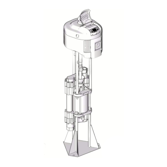
NXT Air-Powered Pump
shown mounted on 218742
Accessory Pump Stand
(not included)
311831E
TI8381a
II 2 G
Advertisement
Table of Contents

Related Manuals for Graco High-Flo


Summary of Contents for Graco High-Flo
- Page 1 List of Models, including maximum working pressures. Related Manuals Part No. Description NXT Air-Powered Pump 311238 NXT Air Motor manual shown mounted on 218742 308048 Viscount Hydraulic Motor manual Accessory Pump Stand 311832 High-Flo Lower manual (not included) Patent Pending TI8381a II 2 G...
-
Page 2: Table Of Contents
Air Line Filter ..... . . 12 Graco Information ......24 Hydraulic Power Supply Check . -
Page 3: Models
S Remote ™ DataTrak XX = X.X:1 ratio Viscount II Hydraulic-Powered Pumps Maximum Pump Working Pressure Connection Cylinder High-Flo Lower Model No. Series psi (MPa, bar) Style Material Material Material (see manual 311832) 243741 400 (2.8, 28) Chromex... -
Page 4: Warnings
Warnings Warnings The following warnings are for the setup, use, grounding, maintenance, and repair of this equipment. The exclama- tion point symbol alerts you to a general warning and the hazard symbol refers to procedure-specific risk. Refer back to these warnings. Additional, product-specific warnings may be found throughout the body of this manual where applicable. - Page 5 Warnings WARNING MOVING PARTS HAZARD Moving parts can pinch or amputate fingers and other body parts. • Keep clear of moving parts. • Do not operate equipment with protective guards or covers removed. • Pressurized equipment can start without warning. Before checking, moving, or servicing equipment, follow the Pressure Relief Procedure in this manual.
-
Page 6: Installation
Installation Installation Grounding Fluid supply container: follow local code. Object being sprayed: follow local code. Solvent pails used when flushing: follow local code. Use only conductive metal pails, placed on a grounded surface. Do not place the pail on a nonconductive sur- The equipment must be grounded. -
Page 7: Accessories
Installation Accessories Hydraulic-Powered Pumps For typical installation, see F . 4 on page 10. Install the following accessories in the order shown in . 3 and F . 4, using adapters as necessary. Hydraulic Power Supply CAUTION Accessory Air Control Kits are available for the NXT Air Motor. -
Page 8: All Pumps
• Gun or valve: to dispense fluid. • Fluid line swivel: for easier gun movement. • Suction kit: enables the pump to draw fluid from a container. 8689a Customer must supply. Graco adapter 193202. Requires seal 193424. 311831E... -
Page 9: Air-Powered Pumps
Installation Air-Powered Pumps TI8435a . 3: Typical Installation Key: Mix Tank Pump Stand Fluid Supply Line; 2 in. (50 mm) minimum diameter Fluid Shutoff Valve Fluid Line Surge Tank Stand Surge Tank Air Supply Line Air Line Filter Air Regulator and Gauge Bleed-Type Master Air Valve Fluid Drain Valve Air Line Drain Valve... -
Page 10: Hydraulic-Powered Pumps
Installation Hydraulic-Powered Pumps TI8436a . 4: Typical Installation Key: Mix Tank Pump Stand Fluid Supply Line; 2 in. (50 mm) minimum diameter Fluid Shutoff Valve Fluid Line Surge Tank Stand Surge Tank Hydraulic Supply Line Shutoff Valve Hydraulic Pressure Gauge Flow Control Valve Pressure Reducing Valve Drain Line... -
Page 11: Operation
Operation Operation Pressure Relief Procedure Trigger Lock Always engage the trigger lock when you stop spraying to prevent the gun from being triggered accidentally by hand or if dropped or bumped. 1. Engage trigger lock. Pump Operation 2. Air-Powered Pumps only: Close the bleed-type master air valve. -
Page 12: Maintenance
Tighten the nut firmly and then turn Wetcup Maintenance the nut another 1/4 turn. If you have a torque wrench, tighten the packing nut to 20-25 ft-lb (27-34 N•m). Fill the wetcup/packing nut (12) one-half full with Graco Throat Seal Liquid (TSL). Maintain level daily. 311831E... -
Page 13: Troubleshooting
Troubleshooting Troubleshooting 1. Relieve the pressure. 2. Check all possible problems and solutions before disassembling pump. To reduce the risk of serious injury whenever you are instructed to relieve pressure, always follow the Pres- sure Relief Procedure on page 15. PROBLEM CAUSE SOLUTION... -
Page 14: Repair
Repair Repair 3. Insert the collars (G) into the coupling nut (K). Tighten the coupling nut onto the motor shaft (F) • To service the lower, see manual 311832. and torque to 145-155 ft-lb (196-210 N•m). • To service the air motor, see manual 311238. 4. -
Page 15: Reassemble The Tie Rods To The Motor
Repair Viscount II Pump Shown Torque to 145-155 ft-lb (196-210 N•m). Torque to 50-60 ft-lb (68-81 N•m). Apply lubricant and PTFE tape. TI8385a Reassemble the Tie Rods to the Motor Use this procedure only if the tie rods (C) have been disassembled from the motor. - Page 16 Repair 311831E...
-
Page 17: Parts
Common Parts Ref. No. Description Part No. Qty. 101 MOTOR, NXT, see manual 311238 see table, below 102 LOWER, High-Flo, see manual 311690 see table, below 103 NUT, coupling 186925 104 COLLAR, coupling 184129 105 ADAPTER, coupling 15H370 106 TIE ROD, 19.307 in. (490.398 mm) -
Page 18: Viscount Ii Pumps
Ref. No. Description Part No. Qty. 101 MOTOR, Viscount II, see manual 223646 308048 102 LOWER, High-Flo, see manual 311832 see table, below 103 TIE ROD, 12.72 in. (323 mm) between 180487 shoulders 104 NUT, lock, hex; 5/8-11 102216 105 NUT, coupling... -
Page 19: Dimensions
Dimensions Dimensions Mounting Stand Hole Layout 160.2 mm 160.2 mm (6.41 in.) (6.41 in.) 30° 30° 60° 277.5 mm (11.1 in.) 185.0 mm (7.4 in.) radius Threaded 17 mm (0.68 in.) holes TI8381a Air-Powered Pumps Approx. Weight Pump Model in. (mm) in. -
Page 20: Technical Data
Technical Data Technical Data NXT Air-Powered Pumps Maximum Fluid Flow at Fluid Maximum Maximum 60 cycles per Pump Cycles Temperature Working Pressure Air Input Pressure minute per Gallon Rating Model psi (MPa, bar) psi (MPa, bar) Air Consumption gpm (lpm) (Liter) °F (°C) JX33XX... - Page 21 Technical Data 0.7 MPa, 7 bar (100 psi) air pressure 0.5 MPa, 4.9 bar (70 psi) air pressure 0.3 MPa, 2.8 bar (40 psi) air pressure Test Fluid: No. 10 Weight Oil NXT 6500 with 3000cc Lower Pumps (JX44XX) psi (MPa, bar) 450 (3.10, 31.0) 400 (2.75, 27.5) 350 (2.41, 24.1)
-
Page 22: Viscount Ii 300 Pumps Models 243742, 243755, & 243756
Technical Data Viscount II 300 Pumps Models 243742, 243755, & 243756 Category Data Maximum Fluid Working Pressure 2.1 MPa 21 bar (300 psi) Maximum Hydraulic Fluid Pressure 10.3 MPa, 103 bar (1500 psi) Fluid Flow at 60 Cycles per Minute 237 liters/min (63 gpm) Cycles Per Liter (gallon) 0.24 (0.93) -
Page 23: Viscount Ii 400 Pumps Models 243741, 243753, & 243754
Technical Data Viscount II 400 Pumps Models 243741, 243753, & 243754 Category Data Maximum Fluid Working Pressure 2.8 MPa, 28 bar (400 psi) Maximum Hydraulic Fluid Pressure 10.3 MPa, 103 bar (1500 psi) Fluid Flow at 60 Cycles per Minute 178 liter/min (47 gpm) Cycles Per Liter (gallon) 0.34 (1.3) -
Page 24: Graco Standard Warranty
With the exception of any special, extended, or limited warranty published by Graco, Graco will, for a period of twelve months from the date of sale, repair or replace any part of the equipment determined by Graco to be defective.
Need help?
Do you have a question about the High-Flo and is the answer not in the manual?
Questions and answers