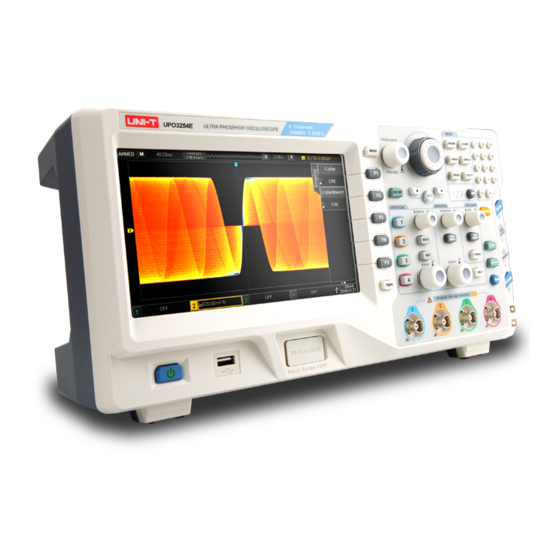
UNI-T UPO3000E Series User Manual

UNI-T UPO3000E Series User Manual

Ultra phosphor oscilloscope
Hide thumbs Also See for UPO3000E Series:
Table of Contents

Advertisement

Quick Links

UPO3000E Series
Ultra Phosphor Oscilloscope
User Manual
UPO3254E

Advertisement

Table of Contents
loading

Summary of Contents for UNI-T UPO3000E Series

  • Page 1 UPO3000E Series Ultra Phosphor Oscilloscope User Manual UPO3254E...
  • Page 2 UNI-T or an This warranty is written by UNI-T for this product, and it is used to substitute authorized UNI-T distributor.
  • Page 3: General Safety Overview

    Please do not operate in flammable and explosive environment. Avoid fire and personal injury. Please keep the product surface clean and dry. Use the correct power line: Only use the dedicated UNI-T power supply appointed to the local region or country for this product. Safety Terms and Symbols Correct plug: Don't plug when the probe or test wire is connected to the voltage source.
  • Page 4: Upo3000E Series Ultra Phosphor Oscilloscope Introduction

    UPO3254E 250MHz computer. UPO3000E Series Ultra Phosphor Oscilloscope is based on UNI-T’s unique Ultra Phosphor technology. A multifunctional, high-performance oscilloscope that is easy to use, with excellent technical specifications, a perfect combination of many functionalities that help users to quickly complete testing.
  • Page 5: Table Of Contents

    -------------------------------------------------------------- 1 4.2 Acquisition Mode ------------------------------------------------------------ 17 Safety Terms and Symbols ------------------------------------------------------------ 1 4.3 Memory Depth --------------------------------------------------------------- 18 UPO3000E Series Ultra Phosphor Oscilloscope Introduction ------------- 2 Chapter 5 Trigger System Settings ----------------------------------------------- 18 Chapter 1 Getting Started Guide --------------------------------------------------- 5 5.1 Trigger System Interpretation -------------------------------------------- 18...
  • Page 6 Table of Content Chapter 8 Display System Settings ----------------------------------------------- 42 Chapter 14 System Prompts and Troubleshooting ---------------------------- 56 8.1 Waveform Display Setting ------------------------------------------------ 42 14.1 System Prompt Information Description ----------------------------- 56 8.2 XY Mode ---------------------------------------------------------------------- 42 14.2 Trouble Shooting ---------------------------------------------------------- 56 8.3 Application of XY Mode --------------------------------------------------- 43 Chapter 15Technical Index ---------------------------------------------------------- 58 Chapter 9 Automatic Measurement ----------------------------------------------- 44...
  • Page 7: Chapter 1 Getting Started Guide

    (2) Check Attachment with a 1 kHz frequency. Please check Appendix A for the list of accessories. If any of the accessories are missing or damaged, please contact UNI-T distributor or local office of this product. (3) Machine Inspection Probe compensation...
  • Page 8: Front Panel

    2.Observe the waveform displayed. Screen display area Multipurpose knob Waveform recording setting Excessive compensation Correct compensation Insufficient compensation Picture 1-2 Probe compensation calibration Shuttle knob 3.If the displayed waveform does not look like the above “correct compensation” Function menu waveform, use a non-metallic screwdriver to adjust the probe’ s variable capacitance until the display matches the "correct compensation"...
  • Page 9: Rear Panel

    1.5 Operation Panel 1.4 Rear Panel (1) Vertical Control ① 1 , 2 , 3 , 4 : Analog channel setting keys indicate CH1, CH2, CH3, and CH4. The four channel labels are identified by different colors also Picture 1-4Oscilloscope Rear Panel corresponding to the colors of the waveforms on the screen and the ①.
  • Page 10 2. Horizontal control 4.Auto Setting a. HORI MENU : Displays extended window, When this key is pressed, the oscilloscope will automatically adjust independent time base and trigger hold-off. the vertical scale factor, sweep time base, and trigger mode according b. Horizontal POSITION : When adjusting the knob, to the input signals.
  • Page 11 10. Shuttle Knob STORAGE: Press this key to enter the storage interface. The types that can For certain numeric parameters that can be set in a large range, be stored include: settings, waveforms. You can store either in the oscilloscope this knob provides a quick-adjust function.
  • Page 12: User Interface

    1.6 User Interface c. Trigger edge: The types are rising, falling, and any kinds. For example, Indicates trigger at the rising edge. d. Trigger coupling: The types are DC, AC, high frequency suppression, low frequency suppression, and noise suppression. For example, indicates DC coupling.
  • Page 13: Special Symbols Introduction

    1.7 Special Symbols Introduction Take the left menu as an example: : Indicates there is a next level menu. : Indicates there is a drop-down menu. : Indicates that the menu has two options. : Indicates that user can adjust by the Multipurpose knob. : The number of circles indicates the total pages of the menu.
  • Page 14: Chapter 2 Vertical Channel Settings

    Chapter 2 Vertical Channel Settings UPO3000E provides 4 or 2 analog input channels. The 4 analog channels 2.3 Bandwidth limitation are CH1~CH4, and the 2 analog channels are CH1 and CH2. The vertical Press 1 bandwidth limitation to turn on the bandwidth limitation (The B system setting method for all channels are exactly the same.
  • Page 15: Invert

    2.6 Invert 2.8 Unit Press 1 invert to turn on the reverse phase. The waveform voltage value Select the amplitude unit for the current channel. Press 1 PgDn unit will be inverted, and the inverted flag will appear in the vertical status bar. and adjust the Multipurpose knob to select the unit of “V”, “A”, “W”...
  • Page 16: Roll Mode

    Waveform before magnification 3.2 ROLL Mode Extended time base When the trigger mode is auto, adjust the SCALE knob in the horizontal control area to change the horizontal scale to be slower than 40ms/div, the oscilloscope will be in ROLL mode and will continuously plot the voltage-time trend chart of the waveform on the screen.
  • Page 17: Trigger Hold-Off

    As shown below, CH1 is a 10Hz sine wave, CH2 is a 1kH square wave, CH3 is a 10kHz triangular wave, CH4 is a 100kHz pulse wave. By using the independent time base, signals with different time base can be observed clearly at the same time.
  • Page 18: Chapter 4 Sampling System Settings

    Sampling rate refers to the time interval between two sampling points. The High resolution Sampling in high-resolution mode Mode maximum sampling rate of the UPO3000E series is 2.5 GS/s. Envelope Sampling in envelope mode The sampling rate will be affected by the time base scale and the memory...
  • Page 19: Acquisition Mode

    (2) Peak Sampling 2. Waveform aliasing: Since the sampling rate is less than 2 times of the In this acquisition mode, the maximum and minimum values of the input actual signal frequency (Nyquist Frequency), the frequency of the reconstructed signal are found at each sampling interval, and the waveform is displayed signal will be less than the actual signal frequency.
  • Page 20: Memory Depth

    4.3 Memory Depth Input Channel: Select any one of the analog signal input terminal The memory depth refers to the number of waveform points that the CH1~CH4 on the front panel of the oscilloscope as a trigger signal. oscilloscope can store in one trigger acquisition. It reflects the storage capacity External Trigger: Select the EXT Trig (EXT or EXT /5 input terminal) of the acquisition.
  • Page 21: Edge Trigger

    (3) Trigger Coupling 5.2 Edge Trigger Trigger coupling determines which component of the signal will be transmitted to the trigger circuit. The coupling type includes DC, AC, low frequency Edge trigger uses the rising or falling edge of the trigger signal to generate suppression, high frequency suppression, and noise suppression.
  • Page 22: Pulse Width Trigger

    5.3 Pulse Width Trigger Pulse Width Polarity: The pulse width trigger determines the trigger time according to the pulse Press the pulse width polarity key to select the positive pulse width and width, you can capture the pulse by setting the pulse width condition. negative pulse width.
  • Page 23: Slope Trigger

    Tip: In order to observe the waveform details more clearly in the video signal, Press the slope button to select the slope trigger edge: rising edge and falling you can set the memory depth a little bigger. The UPO3000E series utilize edge.
  • Page 24: Runt Trigger

    5.6 Runt Trigger Condition: The runt trigger is used to trigger a pulse that has crossed one trigger level Press the condition button to select the trigger condition: “>”, ”<”, ”=”. but not the other. In this oscilloscope, the positive runt pulse is the pulse (1) >: Triggers when the slew rate of the trigger signal is greater than the set that crosses the lower limit of the trigger level but does not cross the upper slew rate.
  • Page 25: Window Trigger

    Polarity: At this time, the trigger setting information is displayed at Press the polarity key to select the trigger polarity: positive and negative. the upper right corner of the screen, the trigger type is window, the trigger (1) Positive: Set to trigger on the positive runt pulse. source is CH1, and the low level of the trigger level is 124mV.
  • Page 26: Delay Trigger

    Trigger Level: Set edge 1 and edge 2 as the rising edge, △ T is the range marked in red in Press PgDn trigger level to select low level or high level. You can also the above figure. directly press the LEVEL knob in the trigger control area to quickly switch Note: Edge 1 and edge 2 must be the adjacent edges.
  • Page 27: Timeout Trigger

    Condition: Press PgDn condition to select: >, <, < >, > <. (1) >: Triggers when the time difference (△T) between the edge set by source 1 and the edge set by source 2 is greater than the set time limit. (2) <: Triggers when the time difference (△T) between the edge set by source 1 and the edge set by source 2 is less than the set time limit.
  • Page 28: Duration Trigger

    (2) Falling edge: Set to start timing when the falling edge of the input signal Press TRIG MENU type, select duration by the Multipurpose knob. You passes the trigger level. can also switch the trigger type by consecutively pressing the type key, then (3) Any edge: Set to start timing when any edges of the input signal pass the press the Multipurpose knob to confirm.
  • Page 29: Setup/Hold Trigger

    Condition: Press the condition key to select: >, <, < >. (1) >: Triggers when the code duration is greater than the set time. (2) <: Triggers when the code duration is less than the set time. (3) < >: Triggers when the code duration is less than the set upper time limit and greater than the set lower time limit.
  • Page 30: Nth Edge Trigger

    Clock Edge: Press the clock edge key to select the clock edge type: rising edge, or falling edge. (1)Rising edge: Set the clock edge type to rising edge. (2)Falling edge: Set the clock edge type to falling edge. Setup/Hold: Press PgDn setup/hold to select setup, hold, setup &...
  • Page 31: Code Pattern Trigger

    Nth Edge Trigger Menu Idle Time: Adjust the Multipurpose knob (shuttle knob or numeric keypad) to set the Source: idle time. Press the source key to select the trigger source, you can select CH1, CH2, CH3, or CH4. The currently selected source is displayed at the upper right corner of the screen.
  • Page 32: Chapter 6 Protocol Decoding

    Chapter 6 Protocol Decoding RS232 Selection: Press DECODE type, and select RS232 by the Multipurpose knob. You UPO3000E decodes the input signals of the analog channels using common can also switch the trigger type by consecutively pressing the type key, then protocols, including parallel, RS232, I2C, SPI, CAN, LIN, and FlexRay.
  • Page 33 Trigger Condition: Press the polarity key to select 2400bps, 4800bps, 9600bps, 19200bps, Press PgDn trigger condition to select start of frame, error frame, parity 38400bps, 57600bps, 115200bps, or user-defined. When selects the error, and data. user-defined option, adjust the baud rate by the Multipurpose knob or the (1) Start of Frame: The waveform trigger is at the start bit of the RS232 shuttle knob.
  • Page 34: I2C Decode (Optional)

    (3) Even List: Displays the decoded data, corresponding line number , time and error information of the data line in a tabular form for easily observe the longer decoded data. (4) Pseudo Square Wave: Select on and the bus shows a square wave with logic 1 for high level and logic 0 for low level.
  • Page 35: Usb Decode (Optional)

    Trigger Condition: =: Valid when the trigger condition is data or address/data, triggers when Press PgDn trigger condition to set the I2C trigger condition: Start, restart, the actual I2C protocol data is equal to the set data. stop, loss, address, data, address & data. (2) Bytes: Valid when the trigger condition is data or address/data, set the (1) Start: Triggers at the start time, that is, while the SCL is in high level, the data byte size of the specified data from 1~5.
  • Page 36: Can Decode (Optional)

    D - Source: 6.4 CAN Decode (Optional) Press the D - source key to set any of CH1 ~ CH4 as the USB D- input. CAN (Controller Area Network) is a kind of serial communication protocol, which allows devices on the network to communicate with each other directly, Speed: and there is no need for the host to control the communication on the network.
  • Page 37 Sample %: (2) Remote Frame: Triggers on the remote frame of the CAN protocol signal. Adjust the Multipurpose knob or shuttle knob to set the “Input -” sampling Remote frames are the same as data frames except that there is no data point ratio (1%~99%).
  • Page 38: Spi Decode (Optional)

    Please refer to the Trigger Setting in the “Edge Trigger” section for more details. Note: At least 3 output channels are required. Therefore, this function is only available on the 4-channel product of UPO3000E series oscilloscopes. 6.5 SPI Decode (Optional)
  • Page 39 MISO Source: Trigger Condition: Press the MISO source key to set any of CH1~CH4 as the data MISO input Press PgDn trigger condition to set the SPI trigger condition: Enable of the SPI decoded signal. chip select or idle time. Enable chip select includes CS, CS &...
  • Page 40: Chapter 7 Mathematical Operation

    Source 2: Press the source 2 key to select any of CH1, CH2, CH3, CH4 as source 2 UPO3000E series oscilloscope carries a variety of mathematical operations: of mathematical operations. Math: Source 1 + source 2, source 1 - source 2, source 1 * source 2,...
  • Page 41: Logic Operation

    Window: Window function, press the window key to select Hamming, Blackman, FFT Operation Tips Rectangle, or Hanning. Signals with DC components or deviations can cause errors or deviations (1) Rectangle: It has the best frequency resolution and the worst amplitude in the FFT waveform components.
  • Page 42: Digital Filter

    7.4 Digital Filter Source 1 Source 2 Source1 Press MATH type, select digital filter to enter its menu. Source: Press the source key to select any of CH1, CH2, CH3, CH4 as the source of digital filter. Filter Type: Press the filter type key to select low pass, high pass, band pass or band stop.
  • Page 43: Advanced Operation

    7.5 Advanced Operation Descriptions Functions Press MATH type, select advanced operation to enter its menu. Calculates the logarithm of the selected source. Calculates the index of the selected source. Expression: Press the expression key to select on or off. If you select on, it will pop up Calculates the sine value of the selected source.
  • Page 44: Chapter 8 Display System Settings

    Persist: Chapter 8 Display System Settings Press DISPLAY persist to select MIN, 50ms, 100ms, 200ms, 500ms, 1s, 2s, 5s, 10s, 20s or infinite. 8.1 Waveform Display Setting You can set the waveform display type, display format, duration, grid brightness, Color Temperature: waveform brightness, and color temperature.
  • Page 45: Application Of Xy Mode

    Adjust the vertical SCALE knob to change the amplitude of each channel, According to sinθ = A/B or C/D, θ is the phase difference angle between and adjust the horizontal SCALE knob to change the time base to get a better channels, and the definition of A, B and C, D are shown above, it can be calculated that the phase difference angle θ...
  • Page 46: Chapter 9 Automatic Measurement

    Chapter 9 Automatic Measurement Time: 9.1 Parameter Measurement UPO3000E series oscilloscope can automatically measure 34 kinds of parameters. Voltage: Period: Time between two consecutive, same-polarity edges of a repetitive waveform. Frequency: The reciprocal of the period Rise time: Time needed for waveform amplitude rising from 10% to 90%.
  • Page 47: Automatic Measurement Menu

    Others: Close this function. +Duty: Ratio of positive pulse width to period. Automatic calculates and displays the -Duty: Ratio of negative pulse width to period. current user defined parameters of the OverSht: (Vmax - Vtop) / Vamp average, maximum, and minimum. Peak PreSht: (Vmin - Vbase) / Vamp Only applicable when user defined...
  • Page 48: All Parameters Measurement

    9.3 All Parameters Measurement Press the user defined F3 key to close the user defined parameter Press MEASURE all parameters, select on to measure 34 parameters selection menu and the parameters will be displayed at the bottom of the at one time, as shown below: screen.
  • Page 49: Chapter 10 Cursor Measurement

    Chapter 10 Cursor Measurement BX-AX: The time measurement. 1/|BX-AX|: The reciprocal of time, or frequency. The cursor can be used to measure the X axis value (time) and the Y axis For a periodic signal, if the AX and BX are set at the same position on the value (voltage) of the selected waveform.
  • Page 50: Chapter 11 Storage And Load

    The Multipurpose knob can be used to adjust the horizontal cursor AY on the Filename can be chosen with the Multipurpose knob. Names can be chosen from set001, Filename screen, press the Multipurpose knob to switch to cursor BY, the adjustment set002, …., set255 method of cursor BY is the same as AY.
  • Page 51: Print Screen

    REF Waveform Load Menu After loading, the Ref waveform status will be displayed in the lower left Options Descriptions corner, including time base scale and amplitude scale. At this point you Functions can use the vertical and horizontal control knob to adjust the Ref Ref-A, wavform’s position on the screen, the time base scale, and the amplitude Select any of the four references to...
  • Page 52: Chapter 12 Auxiliary Function Settings

    Chapter 12 Auxiliary Function Settings Frequency meter: Press the UTILITY key to enter the auxiliary function settings menu. Press UTILITY PgDn frequency meter, select on and will be displayed at the top of the screen. 12.1 System Function Settings The frequency meter is the counter of trigger event frequency in the trigger channel, it is valid when trigger type is edge or pulse width.
  • Page 53: Waveform Recording

    Subnet Mask: Playback Delay: The format of the subnet mask is nnn.nnn.nnn.nnn, the nnn range is from 0 Set the interval time between each frame during the waveform playback. to 255. It is recommended that you consult your network administrator for Press playback delay, and adjust the Multipurpose knob (shuttle knob or an available subnet mask.
  • Page 54: Pass/Fail

    12.3 Pass/Fail Stop Setting: The Pass/Fail uses a template to detect whether the input signal satisfies Press PgDn stop setting to enter its menu as follows: the template requirements. If the input signal exceeds the limited range of Options Descriptions Functions the template, it is judged as failed.
  • Page 55: System Upgrade

    ④ Set source: Press the source key and set the source to CH1. ② Download the upgrade file from the UNI-T website or get it from the UNI-T ⑤ Open message: Press the message key and select on.
  • Page 56: Chapter 13 Additional Function Keys

    Press the CLEAR button on the front panel of the oscilloscope to clear the loaded REF waveform on the screen. 13.4 Factory Setting By pressing the DEFAULT button, you can quickly restore to factory settings. UPO3000E series oscilloscope factory settings are as below: System...
  • Page 57 Bias Voltage Vertical System CH2, CH3, CH4 MATH, REF Extended Window Horizontal System Horizontal Time Base 1μs/div Horizontal Displacement 0 (Horizontal midpoint) Hold-off Time 100.00ns Trigger Type Edge Source Trigger System Slope Type Rising Coupling Mode Trigger Mode Automatic Type Vector Format Display...
  • Page 58: Chapter 14 System Prompts And Troubleshooting

    ④ After completing the above steps, restart the oscilloscope. trigger level has exceeded the waveform range. If so, center the trigger ⑤ If you still cannot use this product normally, please contact UNI-T and level or set the trigger mode to auto with the AUTO key.
  • Page 59: Chapter 15Technical Index

    Chapter 15 Technical Index Aside from specification labeled "typical", all specifications are guaranteed. Unless otherwise stated, all technical specifications are applicable to probes with attenuation 10X and UPS3000CS series oscilloscope. Oscilloscope must first meet the following two conditions in order to achieve these standards: The instrument must be operated at the specified operating temperature for more than thirty minutes.
  • Page 60 Low Frequency Response ≤5 Hz ( on BNC ) (AC coupling, -3dB) DC Gain Accuracy ≤±3% (Sampling or average sampling method) ≤±3% (Sampling or average sampling method) DC Offset Accuracy DC to maximum bandwidth: >40 dB Channel Isolation Horizontal Timing Scale 2ns/div ~ 40s/div (1-2-4 base) ≤±(50+ 2×Service Life)ppm Timing Accuracy...
  • Page 61 Trigger Internal: Center of the screen ±8 grids; External: ±1.8V; EXT/S:±9V Trigger Level Range Trigger Mode Automatic, normal, single Trigger Hold-off Range 80ns ~ 10s High Frequency Suppression 80kHz Low Frequency Suppression 8kHz Reduces waveform noise (10 mV/div ~ 20 V/div, the sensitivity of DC coupling trigger is reduced 2 times) Noise Suppression Trigger Sensitivity ≤1div...
  • Page 62 Window Trigger Window Type Rising edge falling edge any edge Trigger Position Window enter exit time Window time Edge Trigger Edge Type Rising edge, falling edge Idle Time 6.4ns ~ 10s Number of Edges 1 ~ 65535 Delay Trigger Edge Type Rising edge falling edge Delay Type...
  • Page 63 Setup/Hold Trigger Edge Type Rising edge, falling edge Data Type H, L Setup Time 6.4ns~10s Hold Time 6.4ns~10s Slope Trigger Positive slope (greater than, less than, specified range) Slope Condition Negative slope (greater than, less than, specified range) Time Setting 6.4ns~10s Video Trigger Supports standard NTSC, PAL and SECAM broadcast system with line numbers ranging...
  • Page 64 I2C Decode (Optional) Trigger Condition Start, restart, stop, lost acknowledgment , address, data, address/data Address byte Width 7 bits, 10 bits Address Range 0 to 119, 0 to 1023 Byte Size 1bit to 5bits Equal to, greater than, less than Data Qualifier SPI Decode (Optional) Trigger Condition...
  • Page 65 Sampling Point 1% to 99% Frame Type Data frame, remote frame, error frame and overload frame Measure Voltage difference between cursors (△ Time difference between cursors (△ Manual △ /△ The reciprocal of Cursor Tracking Mode Voltage and time at waveform point Allows cursor display during automatic measurement Indicator Maximum minimum peak...
  • Page 66 Digital Filter Low-pass, high-pass, band-pass and band-stop Logic Operation AND, OR, NOT, XOR Advanced Operation Log, Exp, Sin, Cos, Tan, Sqrt, Inth, Diff Storage Internal (256), external USB storage device Setting Internal (256), external USB storage device Waveform Bitmap External USB storage device, it can also store the relevant parameter information. Display Display Type 8-inch TFT LCD...
  • Page 67 General Technical Specifications Probe Compensation Signal Output Output Voltage About 3Vp Frequency 10Hz 100Hz 1kHz default 10kHz Power Supply Power Supply Voltage 100V 240VACrms Frequency 45Hz 440Hz Fuse T 250V Environment Temperature Range Operational Operational ℃~ + ℃~+ ℃; ℃ Cooling Method Fan forced cooling Humidity Range...
  • Page 68: Chapter 16Accessories

    In addition to permit provided by this summary or other applicable insurance order from the local UNI-T dealers guarantee T does not provide any other explicit or implied guarantee Appendix B Maintenance and Cleaning...

This manual is also suitable for:

Upo3152eUpo3252eUpo3154eUpo3254e

Table of Contents