Sign In
Upload
Download
Table of Contents
Contents
Add to my manuals
Delete from my manuals
Share
URL of this page:
HTML Link:
Bookmark this page
Add
Manual will be automatically added to "My Manuals"
Print this page
×
Bookmark added
×
Added to my manuals
Manuals
Brands
UNI-T Manuals
Test Equipment
UPO2000E Series
User manual
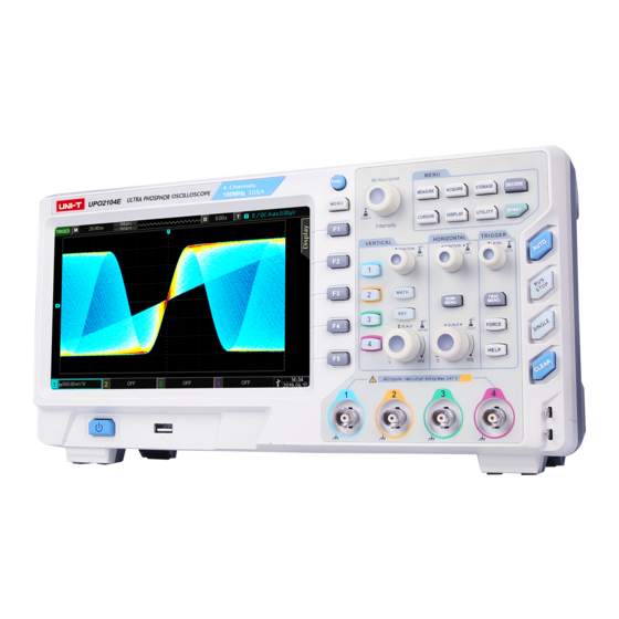
UNI-T UPO2000E Series User Manual
Ultra phosphor oscilloscope
Hide thumbs
Also See for UPO2000E Series
:
Programming manual
(94 pages)
1
2
3
4
5
Table Of Contents
6
7
8
9
10
11
12
13
14
15
16
17
18
19
20
21
22
23
24
25
26
27
28
29
30
31
32
33
34
35
36
37
38
39
40
41
42
43
44
45
46
47
48
49
50
51
52
53
54
55
56
57
58
59
60
61
62
63
64
65
66
page
of
66
Go
/
66
Contents
Table of Contents
Troubleshooting
Bookmarks
Table of Contents
General Safety Overview
Safety Terms and Symbols
Preface
UPO2000E Series Ultra Phosphor Oscilloscope Introduction
Table of Contents
Table of Content
Chapter 1 Introduction Guide
General Inspection
Check for Damages Caused by Transport
Check Attachment
Machine Inspection
Before Use
Connect to the Power Supply
Boot Check
Connect Probe
Function Check
Probe Compensation
Front Panel
Rear Panel
Operation Panels
Vertical Control
Horizontal Control
Trigger Control
Auto Setting
Run/Stop
Single Trigger
Clear
Print Screen
Multipurpose Knob
Function Keys
User Interface
Special Symbols Introduction
Chapter 2 Vertical Channel Settings
Open/Activate/Close Analog Channel
Channel Coupling
Bandwidth Limitation
Volts/DIV
Probe
RP (Reverse Phase)
Bias
Unit
Chapter 3 Horizontal System Settings
Horizontal Scale
ROLL Mode
Extended Window
Independent Time Base
Trigger Hold-Off
Chapter 4 Sampling System Settings
Sampling Rate
Sampling and Sampling Rate
Low Sampling Rate Effect
Acquisition Mode
Normal Sampling
Peak Sampling
High Resolution
Envelope
Average
Storage Depth
Chapter 5 Trigger System Settings
Trigger System Interpretation
Trigger Source
Trigger Mode
Trigger Coupling
Trigger Sensitivity
Pre-Trigger / Delayed Trigger
Forced Trigger
Edge Trigger
Pulse Width Trigger
Video Trigger
Slope Trigger
Runt Trigger Menu
Window Trigger
Delayed Trigger
Timeout Trigger
Duration Trigger
Setup/Hold Trigger
Nth Edge Trigger
Code Pattern Trigger
Chapter 6 Protocol Decoding
RS232 Decoding
I2C Decode
SPI Decode
Chapter 7 Mathematical Operations
Mathematical Function
Fft
Logic Operation
Digital Filter
Advanced Operation
Chapter 8 Display System Settings
Waveform Display Setting
XY Mode
Application of XY Mode
Chapter 9 Automatic Measurement
Parameter Measurement
Automatic Measurement Menu
All Parameters Measurement
User Defined Parameters
Chapter 10 Cursor Measurement
Time Measurement
Voltage Measurement
Chapter 11 Storage and Callback
Setting Storage and Load
Waveform Storage and Load
Print Screen
Chapter 12 Auxiliary Function Settings
System Function Settings
Waveform Recording
Pass/Fail
Function Introduction
Application Example
System Upgrade
Chapter 13 Additional Function Keys
Auto Setting
Run / Stop
Clear
Factory Setting
Chapter 14 System Prompts and Troubleshooting
System Prompt Information Description
Trouble Shooting
Chapter 15 Technical Index
Chapter 16 Accessories
Appendix A Accessories and Options
Appendix B Maintenance and Cleaning
Appendix C Warranty Overview
Appendix D Contact Us
Advertisement
Quick Links
1
General Safety Overview
Download this manual
UPO2000E
Series Ultra Phosphor Oscilloscope
User Manual
Table of
Contents
Previous
Page
Next
Page
1
2
3
4
5
Advertisement
Table of Contents
Need help?
Do you have a question about the UPO2000E Series and is the answer not in the manual?
Ask a question
Questions and answers
Related Manuals for UNI-T UPO2000E Series
Test Equipment UNI-T UPO3000E Series Programming Manual
Programmable digital oscilloscope (94 pages)
Test Equipment UNI-T UPO2000CS Series User Manual
Ultra phosphor oscilloscope (94 pages)
Test Equipment UNI-T UPO2072E User Manual
Ultra phosphor oscilloscope (66 pages)
Test Equipment UNI-T UPO2102E User Manual
Ultra phosphor oscilloscope (66 pages)
Test Equipment UNI-T UPO2074E User Manual
Ultra phosphor oscilloscope (66 pages)
Test Equipment UNI-T UPO2104E User Manual
Ultra phosphor oscilloscope (66 pages)
Test Equipment UNI-T UPO2102 User Manual
Digital phosphor oscilloscope (138 pages)
Test Equipment UNI-T MSO2000 Series Quick Start Manual
Digital phosphor oscilloscope (19 pages)
Test Equipment UNI-T UPO2000 Series User Manual
Digital phosphor oscilloscope (130 pages)
Test Equipment UNI-T UPO3000E Series User Manual
Ultra phosphor oscilloscope (69 pages)
Test Equipment UNI-T MSO3252E User Manual
Digital oscilloscope (123 pages)
Test Equipment UNI-T UPO3152E User Manual
Ultra phosphor oscilloscope (69 pages)
Test Equipment UNI-T UPO1202CS Quick Start Manual
Digital phosphor oscilloscope (15 pages)
Test Equipment UNI-T UPO1000 Series Quick Manual
Digital phosphor oscilloscope (18 pages)
Test Equipment UNI-T UPO1000 Series User Manual
Digital phosphor oscilloscope (97 pages)
Test Equipment UNI-T UPO1000HD Series Quick Start Manual
High-resolution oscilloscopes (26 pages)
This manual is also suitable for:
Upo2072e
Upo2102e
Upo2074e
Upo2104e
Table of Contents
Print
Rename the bookmark
Delete bookmark?
Delete from my manuals?
Login
Sign In
OR
Sign in with Facebook
Sign in with Google
Upload manual
Upload from disk
Upload from URL


Need help?
Do you have a question about the UPO2000E Series and is the answer not in the manual?
Questions and answers