
Related Manuals for UNI-T UPO1002 Series


Summary of Contents for UNI-T UPO1002 Series
- Page 1 User’s Manual UPO1002 Series Digital Phosphor Oscilloscope User’s Manual UPO1002 Series Digital Phosphor Oscilloscope REV 0 2024.01 Instruments.uni-trend.com...
- Page 2 UNI-T, pay the shipping cost, and provide a copy of the purchase receipt of the original purchaser. If the product is shipped domestically to the location of the UNI-T service center, UNI-T shall pay the return shipping fee.
- Page 3 This warranty is written by UNI-T for this product, and it is used to substitute any other express or implied warranties. UNI-T and its distributors do not offer any implied warranties for merchant ability or applicability purposes.
- Page 4 User’s Manual UPO1002 Series Digital Phosphor Oscilloscope 1. Introduction This manual includes safety requirements, installment and the operation of UPO1002 series oscilloscope. 2. Safety Requirements This section contains information and warnings that must be followed to keep the instrument operating under safety conditions. In addition, user should also follow the common safety procedures.
- Page 5 User’s Manual UPO1002 Series Digital Phosphor Oscilloscope Safety Sign It indicates possible danger of electric shock, which may cause Danger personal injury or death. It indicates that you should be careful to avoid personal injury or Warning product damage. It indicates possible danger, which may cause damage to this...
- Page 6 User’s Manual UPO1002 Series Digital Phosphor Oscilloscope equipment, such as multi-phase motor and multi-phase fuse box; lighting equipment and lines inside large buildings; machine tools and power distribution boards at industrial sites (workshops). Three-phase public power unit and outdoor power supply line equipment.
- Page 7 Please use power fuse of specified specification. If the fuse needs to be Power fuse replaced, it must be replaced with another one that meets the specified specifications by the maintenance personnel authorized by UNI-T. There are no components available to operators inside. Do not remove the Disassembly protective cover.
- Page 8 If this device may be faulty, please contact the authorized maintenance Abnormality personnel of UNI-T for testing. Any maintenance, adjustment or parts replacement must be done by the relevant personnel of UNI-T. Do not block the ventilation holes at the side and back of this device;...
- Page 9 User’s Manual UPO1002 Series Digital Phosphor Oscilloscope disconnect the power supply first and then wipe the housing with a dry cloth or a slightly moistened soft cloth. Connecting Power Supply The specification of input AC power. Voltage Range Frequency Maximum Power 100-240 VAC(fluctuant: ±10%)...
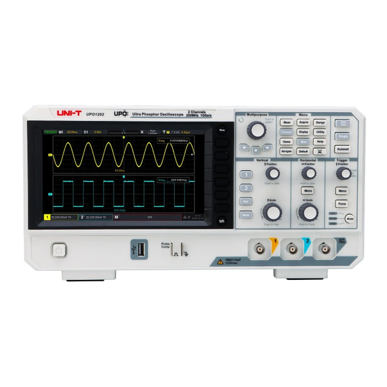
- Page 10 100 MHZ 1 GSa/s UPO1002 series digital phosphor oscilloscope adopts innovative UNI-T 3D technique Ultra Phosphor 2.0 with new appearance upgrade and the function of deep storage, high waveform capture rate, real-time waveform recording and playback and 256-level grayscale display.
- Page 11 (2) Check Attachment Please check appendix for the list of accessories. If any of the accessories are missing or damaged, please contact UNI-T or local distributors of this product. (3) Machine Inspection If the instrument appears to be damaged, not working properly, or has failed the functionality test, please contact UNI-T or local distributors of this product.
- Page 12 To perform a quick verification of the instrument’s normal operations, please follow the steps below. (1) Connecting to the Power Supply AC power specification of UPO1002 series digital storage oscilloscope refers to the section of . Use the assembled power line or other power line that meets the local Connecting Power Supply country standards to connect the oscilloscope.
- Page 13 User’s Manual UPO1002 Series Digital Phosphor Oscilloscope measurement errors or mistake. Please follow the following steps. Set the attenuation coefficient in the probe menu to 10x and the switch of the probe at 10x, and connecting the probe of the oscilloscope to CH1. If use the probe’s hook head, make sure it stably touch to the probe.
- Page 14 User’s Manual UPO1002 Series Digital Phosphor Oscilloscope Description Description Horizontal control area Screen display area (Horizontal) Multipurpose rotary knob Analog channel input port (Multipurpose) Navigation function area Vertical control area(Vertical) Functional menu key Menu control soft key Probe compensation signal...
- Page 15 User’s Manual UPO1002 Series Digital Phosphor Oscilloscope 4.5 Operation Panel (1) Function Key Measure: Press this key to enable the measurement setting menu. It can set the measurement source, all parameter measurement, user-defined parameter, measurement statistic, measure indicator, threshold setting and measurement window.
- Page 16 User’s Manual UPO1002 Series Digital Phosphor Oscilloscope (2) Vertical Control Analog channel setting keys respectively represents CH1, CH2. Two channel’s label are identified by different colors and it also corresponding to the colors of waveforms on the screen and the channel input connectors.
- Page 17 User’s Manual UPO1002 Series Digital Phosphor Oscilloscope time base step is 1-2-5. This key can be quickly step through main window and extension window. (4) Trigger Control Mode: Press this key to switch the trigger mode to Auto, Normal or Single, the ...
- Page 18 User’s Manual UPO1002 Series Digital Phosphor Oscilloscope (9) Multipurpose Rotary Knob Multipurpose: When in menu operation, press a menu soft key and rotate the rotary knob to select the submenu and then press the rotary knob (i.e. Select function) to confirm the selection.
- Page 19 User’s Manual UPO1002 Series Digital Phosphor Oscilloscope the time base scale will pop out on the screen. Horizontal offset: Display the horizontal offset of the waveform, which can adjusted by press the POSITION rotary knob in horizontal control area on the front panel to return the horizontal offset to 0.
- Page 20 4.8 Remote Control UPO1002 series digital phosphor oscilloscope supports communication with computer via USB and LAN interfaces to realize remote control. The remote control is realized based on SCPI (Standard Commands for Programmable Instruments).
- Page 21 User’s Manual UPO1002 Series Digital Phosphor Oscilloscope software provided by UNI-T. You can download this software on UNI-T official website (https://www.uni-trend.com.cn/). Operation steps Setup the communication between the instrument and computer Running the instrument manager and search the instrument source ...
- Page 22 User’s Manual UPO1002 Series Digital Phosphor Oscilloscope 5. Vertical Channel Setting Open/Activate/Close Analog Channel Channel Coupling Bandwidth Limit Volts/div Probe Reversed Phase Unit Bias Voltage Label UPO1000X provides 2analog input channels, which is CH1~CH2. The vertical system setup method is exactly the same for each channel.
- Page 23 User’s Manual UPO1002 Series Digital Phosphor Oscilloscope Activation state Open but not activated Close state 5.2 Channel Coupling Channel coupling can set to DC, AC or ground. Ground 5.3 Bandwidth Limit Bandwidth limitation can set to 20 MHz or full bandwidth. When soft key menu sets to 20 MHz, the...
- Page 24 User’s Manual UPO1002 Series Digital Phosphor Oscilloscope When the probe is user-defined, it can set to 0.001X~20000X. 5.6 Reversed Phase When reversed phase is turned on, the voltage value of waveform will be reversed and the reversed icon “—” will display in vertical state label (as shown in Figure 5-2)
- Page 25 User’s Manual UPO1002 Series Digital Phosphor Oscilloscope 6. Horizontal System Setting Horizontal Scale ROLL Mode Window Extension XY Multi-Scopes Trigger Holdoff 6.1 Horizontal Scale Horizontal scale is also called horizontal time base, the time value represented by each scale in the horizontal direction of the display screen, it usually expressed as s/div.
- Page 26 User’s Manual UPO1002 Series Digital Phosphor Oscilloscope 6.2 ROLL Mode When trigger mode is automatic, adjusting the SCALE rotary knob in horizontal control area, if the horizontal scale of the oscilloscope is lower than 20 ms/div, the oscilloscope will enter ROLL mode.
- Page 27 User’s Manual UPO1002 Series Digital Phosphor Oscilloscope Waveform before amplification Main time base Extension time base Enlarged waveform Figure 6-3 The waveform before amplification is shown in the square brackets on the upper part of the screen. It can move to right or left by horizontal Position rotary knob or adjusting the horizontal time base SCALE to increasing or decreasing this area.
- Page 28 User’s Manual UPO1002 Series Digital Phosphor Oscilloscope in vertical control area to move XY figure on vertical direction. The amplitude scale of channel can adjust by the SCALE rotary knob in vertical control area. The time base scale can adjust by the SCALE rotary knob in horizontal control area. The adjustment is for gaining the better display effect of Lissajous curve.
- Page 29 User’s Manual UPO1002 Series Digital Phosphor Oscilloscope Application of XY Mode Phase difference between in two signals with the same frequency can be easily observed through Lissajous curve, as shown in Figure 6-6. The following figure explains the observation schematic of the phase difference.
- Page 30 User’s Manual UPO1002 Series Digital Phosphor Oscilloscope 6.5 Multi-Scopes In Multi-Scopes, CH1 ~ CH2 can set to different time base scale for observing the signal with different frequency at the same time. The Multi-Scopes interface is accessed via the horizontal menu.
- Page 31 User’s Manual UPO1002 Series Digital Phosphor Oscilloscope Pulse train width Figure 6-9 Instruments.uni-trend.com 31 / 121...
- Page 32 User’s Manual UPO1002 Series Digital Phosphor Oscilloscope 7. Trigger System Setting Trigger System Noun Edge Trigger Pulse Width Trigger Video Trigger Slope Trigger Runt Pulse Trigger Over-amplitude trigger Delay Trigger Timeout Trigger ...
- Page 33 User’s Manual UPO1002 Series Digital Phosphor Oscilloscope right of the trigger point. In this chapter, take two analog channels (UPO1202) as an example to introduce the vertical channel settings. 7.1 Trigger System Noun Trigger Source A signal is used to generate a trigger. Trigger can...
- Page 34 User’s Manual UPO1002 Series Digital Phosphor Oscilloscope Only collect the particular event appointed by the trigger setting; Rare trigger event, use normal mode can prevent the oscilloscope from automatic trigger, so that the waveform can be stable display.
- Page 35 User’s Manual UPO1002 Series Digital Phosphor Oscilloscope 7.2 Edge Trigger The edge can be triggered by looking for the specific edge (rising edge, falling edge and random edge) on waveform and electrical level. Press edge trigger menu to set source, trigger coupling, trigger mode and edge type.
- Page 36 User’s Manual UPO1002 Series Digital Phosphor Oscilloscope Positive Pulse Width Negative Pulse Width Figure 7-2 Notes: In parameter setting popups, rotate the Multipurpose rotary knob can switch the menu, and press the Multipurpose rotary knob can select/extend the menu, in pull-down list, rotate the Multipurpose rotary knob to switch the menu options.
- Page 37 User’s Manual UPO1002 Series Digital Phosphor Oscilloscope Trigger Coupling Edge trigger only supports the trigger coupling DC or noise suppression. 7.4 Video Trigger The video signal includes the image and the time sequence information, it has multiple standards and formats. UPO1002 provides the basic measurement functions, which can be triggered in the filed or line of NTSC (National Television Standards Committee), PAL (Phase Alternating Line) and SECAM (Sequential Couleur A Memoire), as shown in Figure 7-3.
- Page 38 Hints: In order to observe the waveform details in the video signal, user can set the memory depth a little bigger. The UPO1000X series utilize the UNI-T original digital 3D technique, it uses a multi-level greyscale display function so that different brightness can reflect the frequency of different parts of the signal.
- Page 39 User’s Manual UPO1002 Series Digital Phosphor Oscilloscope time of rising/ falling edge”. 3. Level Setting Level setting can set to low level, high level or high-low level. Press LEVEL knob on trigger control area to quickly switch the selection. level: Adjust the low level threshold of slope trigger by using LEVEL knob on trigger control area.
- Page 40 User’s Manual UPO1002 Series Digital Phosphor Oscilloscope shown in Figure 7-4. The runt trigger menu can set source, trigger coupling, trigger mode, polarity (positive, negative), condition (> < irrelevance, <, >, ≤≥), the lower/upper limit of time and level setting.
- Page 41 User’s Manual UPO1002 Series Digital Phosphor Oscilloscope can be set. Notes: Slope time of trigger signal refers to the figure as shown in the following figure “slope time of rising/ falling edge”. 3. Upper/Lower Limit of Time The set pulse width of pulse is compared with the channel’s pulse width. The trigger will be generated when the condition is met.
- Page 42 User’s Manual UPO1002 Series Digital Phosphor Oscilloscope Rising edge Trigger level-high level Trigger level-low level Falling edge Figure 7-5 Notes: In parameter setting popups, rotate the Multipurpose rotary knob can switch the menu, and press the Multipurpose rotary knob can select/extend the menu, in pull-down list, rotate the Multipurpose rotary knob to switch the menu options.
- Page 43 User’s Manual UPO1002 Series Digital Phosphor Oscilloscope greater than or equal to the set over-amplitude time. 4. Level Setting Level setting can set to low level, high level or high-low level. Press LEVEL knob on trigger control area to quickly switch the selection.
- Page 44 User’s Manual UPO1002 Series Digital Phosphor Oscilloscope as shown in Figure 7-6. Notes: Edge 1 and edge 2 must be adjacent edges. Only the channel that has been connected to the signal can get stable trigger. Notes: In parameter setting popups, rotate the Multipurpose rotary knob can switch the menu, and press the Multipurpose rotary knob can select/extend the menu, in pull-down list, rotate the Multipurpose rotary knob to switch the menu options.
- Page 45 User’s Manual UPO1002 Series Digital Phosphor Oscilloscope Edge trigger supports the trigger mode auto, normal and single trigger. 2. Trigger Coupling Edge trigger only supports the trigger coupling: DC. 7.9 Timeout Trigger Timeout trigger can generate the time interval of signal is greater than the set timeout, the signal is cross from the rising edge (or falling edge) of the input signal to the end of adjacent falling edge (rising edge) of the trigger level, as shown in Figure 7-7.
- Page 46 User’s Manual UPO1002 Series Digital Phosphor Oscilloscope 1. Trigger Mode Edge trigger supports the trigger mode auto, normal and single trigger. 2. Trigger Coupling Edge trigger only supports the trigger coupling: DC. 7.10 Duration Trigger When the duration trigger is selected, the oscilloscope identifies the trigger condition by looking for the duration of the specified codes.
- Page 47 User’s Manual UPO1002 Series Digital Phosphor Oscilloscope higher than the trigger level of the channel. b. L: Set the code pattern value of the selected channel to “Low”, that is, the voltage level is lower than the trigger level of the channel.
- Page 48 User’s Manual UPO1002 Series Digital Phosphor Oscilloscope △T1 △T2 △T1 is setup time △T2 is hold time Data source Clock source Data code pattern: H Edge type: rising edge Figure 7-9 Notes: In parameter setting popups, rotate the Multipurpose rotary knob can switch the menu, and press the Multipurpose rotary knob can select/extend the menu, in pull-down list, rotate the Multipurpose rotary knob to switch the menu options.
- Page 49 User’s Manual UPO1002 Series Digital Phosphor Oscilloscope 1. Trigger Mode Edge trigger supports the trigger mode auto, normal and single trigger. 2. Trigger Coupling Edge trigger only supports the trigger coupling: DC. 7.12 Nth Edge Trigger The Nth edge trigger is triggered on the Nth edge after assign the specified idle time. For...
- Page 50 User’s Manual UPO1002 Series Digital Phosphor Oscilloscope b. Falling edge: Set to trigger on the falling edge of the signal. 2. Idle Time The idle time is compared with the pulse time, it will be triggered when the condition is met.
- Page 51 User’s Manual UPO1002 Series Digital Phosphor Oscilloscope each channel is displayed at the bottom of the screen. a. H: Set the code pattern value of the selected channel to "High", that is, the voltage level is higher than the trigger level of the channel.
- Page 52 User’s Manual UPO1002 Series Digital Phosphor Oscilloscope Odd parity: If the number of bit 1 is odd in data bits and parity bits, then the transmission is correct. Even Check: If the number of bit 1 is even in data bits and parity bits, then the transmission is correct.
- Page 53 User’s Manual UPO1002 Series Digital Phosphor Oscilloscope a. Write: It will be triggered when the “read/write” bit in the I C protocol is “write”. b. Read: It will be triggered when the “read/write” bit in the I C protocol is “read”.
- Page 54 User’s Manual UPO1002 Series Digital Phosphor Oscilloscope 6. Data It is valid when the trigger condition is select “address” or “address data”. The range can be 00~FFFFFFFFFF (hexadecimal system). Press Multipurpose rotary knob to set the data. (2)Trigger Setting 1. Trigger Mode Edge trigger supports the trigger mode auto, normal and single trigger.
- Page 55 User’s Manual UPO1002 Series Digital Phosphor Oscilloscope To set the bit width of SPI signal for each frame, the range can be 4~32. 4. Frame Length Set the length for data unit, it can be set when the trigger condition is “chip &data, idle &data”.
- Page 56 User’s Manual UPO1002 Series Digital Phosphor Oscilloscope 8. Automatic Measurement Parameter Measurement Automatic Measurement Menu All Parameter Measurement User-defined Measurement 8.1 Parameter Measurement UPO1002 series digital phosphor oscilloscope can automatically measure 36 kinds of parameters. It includes voltage, time and other parameter.
- Page 57 User’s Manual UPO1002 Series Digital Phosphor Oscilloscope corresponds to the DC voltage that generates equivalent energy. Cycle RMS (CycRMS): The energy produced by the conversion of AC signal in a period, it corresponds to a DC voltage that generates equivalent energy.
- Page 58 User’s Manual UPO1002 Series Digital Phosphor Oscilloscope point of mid-value of the threshold. FRFF: Time from the first rising edge of source 1 to the falling edge of source 2 at the cross point of mid-value of the threshold. FFFR: Time from the falling rising edge of source 1 to the rising edge of source 2 at the cross point of mid-value of the threshold.
- Page 59 User’s Manual UPO1002 Series Digital Phosphor Oscilloscope Cycle area (CycArea): The algebraic sum of the product of voltage at all points and time in a cycle of waveform. Phase: The phase difference between the rising edge of the main source and the rising edge of the secondary source in mid-value of threshold.
- Page 60 User’s Manual UPO1002 Series Digital Phosphor Oscilloscope (6) Indicator Open the indicator to directly point out the physical meaning for the selection indicator parameter by the line. Select the parameter in selection indicator list, it can set to ON or OFF.
- Page 61 User’s Manual UPO1002 Series Digital Phosphor Oscilloscope Figure 8-1 All parameter measurements are always marked with the color that consistent with the current measurement channel (the primary source). If it displays “---”, it indicates that the current measurement source has no signal input or the measured results is not within the valid range (it’s too large or too small.)
- Page 62 User’s Manual UPO1002 Series Digital Phosphor Oscilloscope 9. Cursor Measurement Time Measurement Voltage Measurement Screen Measurement Cursor measurement is used to measure X axis (time) and Y axis (voltage) of the selected waveform, press the Cursor key on the front panel to enter the cursor measurement menu. It supports to measure the multiple channels at the same time and also supports to measure the loading waveform.
- Page 63 User’s Manual UPO1002 Series Digital Phosphor Oscilloscope results of the channel; “Ref X” indicates the time measurement results of reference waveform. “Y” indicates the voltage measurement results at the intersection of the open channel and the cursor, adjusting the horizontal position of AX, BX cursor by the Multipurpose rotary knob to reach the time measurement.
- Page 64 User’s Manual UPO1002 Series Digital Phosphor Oscilloscope Figure 9-3 The cursor measurement display frame in top left corner: “X” indicates the time measurement results; “Ref X” indicates the time measurement results of reference waveform. “Y” indicates the voltage measurement results, adjusting the vertical position of AX, BX, AY, BY cursor by the Multipurpose rotary knob to reach the time measurement and voltage measurement.
- Page 65 User’s Manual UPO1002 Series Digital Phosphor Oscilloscope 10. Sampling System Sampling Rate Acquisition Mode Storage Depth Sampling is the conversion of the signal from an analog input channel, through an analog-to-digital converter (ADC), into a discrete point.
- Page 66 User’s Manual UPO1002 Series Digital Phosphor Oscilloscope Figure 10-1 Waveform Aliasing: Since the sampling rate is 2 times lower than the actual signal frequency (Nyquist frequency), the waveform frequency is less than the frequency of actual signal when sampling data is reconstructing, as shown in Figure 10-2.
- Page 67 User’s Manual UPO1002 Series Digital Phosphor Oscilloscope The oscilloscope samples the signal and reconstruct the waveform with equal time interval in normal mode. For the most of waveform, this mode can produce the optimal display effect. (2) Peak Sampling The oscilloscope finds the maximum and minimum of the input signal from every sampling interval and using these value to display the waveform.
- Page 68 User’s Manual UPO1002 Series Digital Phosphor Oscilloscope storage depth = sampling rate×horizontal time base×the number of grid of horizontal direction The maximum storage depth of UPO1002 is 56 Mpts (per channel). In Acquire menu, user can freely to set the storage depth to auto, 7 k, 70 k, 700 k, 7 M, 28 M, 56 M. The default setting is auto.
- Page 69 User’s Manual UPO1002 Series Digital Phosphor Oscilloscope 11. Display System DISPLAY can set the display type of waveform, display type of grid, grid brightness, waveform brightness, background brightness, persistence time, color temperature, anti-color temperature, menu display and transparency. 11.1 Display Type In DISPLAY menu, it can select the waveform display in vector or point.
- Page 70 User’s Manual UPO1002 Series Digital Phosphor Oscilloscope the minimum, 50 ms, 100 ms, 200 ms, 500 ms, 1 s, 2 s, 5 s, 10 s, 20 s , infinite persistence and DSO. The default value is the minimum. 11.7 Color Temperature Open the color temperature in DISPLAY menu, it can be intuitively reflect the probability of the occurrence of waveform signals.
- Page 71 User’s Manual UPO1002 Series Digital Phosphor Oscilloscope 12. Storage and Recall Storage and Reload Settings Waveform Storage Reload Waveform Recording Convert to Video Picture Storage File System With the storage function, user can save the oscilloscope's settings, waveforms, screen images and recording videos to the oscilloscope’s local or external USB storage devices, and the saved...
- Page 72 User’s Manual UPO1002 Series Digital Phosphor Oscilloscope 12.2 Waveform Storage Table 12-2 Waveform Storage Menu Function Menu Setting Description Type Waveform Source CH1, CH2 Set which channel waveform to be saved. Press the save key, the waveform will be saved in the oscilloscope’s local.
- Page 73 User’s Manual UPO1002 Series Digital Phosphor Oscilloscope Select the waveform of activated channel at the current to quickly perform Quick Reference reference reload, but not save the waveform data. Clear All Turn off all REF waveforms. Reload EF waveform as shown in Figure 12-1.
- Page 74 User’s Manual UPO1002 Series Digital Phosphor Oscilloscope virtual numeric keyboard to set, the maximum can be set to 30. Start the conversion of video from a frame, rotating Start the conversion of Start Frame Multipurpose knob or virtual numeric keyboard...
- Page 75 User’s Manual UPO1002 Series Digital Phosphor Oscilloscope picture preview function. Close and exit the picture preview. Select the file path for the picture preview, it can only preview the picture File Path in the current path and not display the picture in submenu or the upper level.
- Page 76 User’s Manual UPO1002 Series Digital Phosphor Oscilloscope effect.) When picture preview file is visible, that is confirm the file in the current Confirm path and exit the file management. Instruments.uni-trend.com 76 / 121...
- Page 77 User’s Manual UPO1002 Series Digital Phosphor Oscilloscope 13. Auxiliary Function System Function System Update Web Access Press the UTILITY key on the front panel to enter the auxiliary function setting menu. 13.1 System Function Automatic Calibration Automatic calibration allows the oscilloscope to work optimally to obtain the most accurate measurements.
- Page 78 Download the update file from UNI-T official website or ask UNI-T distributor to provide the update file. The update file is the same as the model and hardware version of the instrument, the software version is higher than the version of the instrument.
- Page 79 User’s Manual UPO1002 Series Digital Phosphor Oscilloscope When the instrument is in the shutdown state, insert USB and turn on the instrument, press soft boot-up key, self-checking and process the update. The update process needs to wait for 5 minutes. After the update is completed, turn off the instrument and plug out USB.
- Page 80 User’s Manual UPO1002 Series Digital Phosphor Oscilloscope Figure 13-2 In Web page, click the corresponding key and knob to control the oscilloscope. Multiple operating can be set in screen of the oscilloscope, such as a. Drag waveform cursor to adjust the vertical position of the waveform; drag the trigger position cursor to adjust the trigger position.
- Page 81 User’s Manual UPO1002 Series Digital Phosphor Oscilloscope Access Outer Network Plug the network cable into the oscilloscope and the network can be access to internet. Open frp proxy service on the server. Configure the oscilloscope’s frp proxy IP and port The browser can access the proxy IP: web_port, and the access interface is consistent with the above.
- Page 82 User’s Manual UPO1002 Series Digital Phosphor Oscilloscope Figure 13-5 Click the confirmation after the input is completed, it can be continuously access according to the new modified IP address information (in correct configuration). frp proxy network information setting The setting interface setting as shown in Figure 13-6.
- Page 83 If you forget the password, reset the password by pressing the DEFAULT key on the oscilloscope panel. (5) Service and Support Click service and support can connect to UNI-T official website for more product’s information. Instruments.uni-trend.com 83 / 121...
- Page 84 User’s Manual UPO1002 Series Digital Phosphor Oscilloscope 14. HOME Frequency Meter Waveform Recording Pass/Fail Test Digital Voltage Meter Help Automatic Setting Self-test 14.1 Frequency Meter The state of Frequency Meter can set to ON or OFF. When it sets to ON, a Freq popups will display on the top of the screen, it displays the current frequency meter information of trigger source.
- Page 85 User’s Manual UPO1002 Series Digital Phosphor Oscilloscope (3) Stop Stop the waveform recording. (4) Playback Place back waveform, it can pause by Multipurpose rotary knob and play the specified frame. (5) Fast Acquire Quick recording, which is continuously recording waveform. It is for improving the capture rate of waveform.
- Page 86 User’s Manual UPO1002 Series Digital Phosphor Oscilloscope (3) Source The source is set to compare to the template. The source can only select the channel that is consistent with template reference waveform. (4) Stop Set the stop condition for the test. The test will be automatically stop when the stop condition is met.
- Page 87 UPO1002 Series Digital Phosphor Oscilloscope 14.4 Digital Voltage Meter UPO1002 series has built-in DVM (digital voltage meter), it can measure the voltage of effective 4 digits in any analog channel. DVM measurements are asynchronous with the acquisition system of the oscilloscope and are always operating the acquisition. User can set DVM setting, including voltage meter state, source, mode and limit setting.
- Page 88 User’s Manual UPO1002 Series Digital Phosphor Oscilloscope 14.5 Automatic Setting Autoset(automatic setting/hold) Hold: keep the previous settings Automatic: not save the previous settings (1) Acquisition setting: the acquisition mode and average time will not be changed in hold mode. (2) Trigger source: the trigger source and trigger coupling will not be changed in hold mode. Other setting restores to edge trigger, automatic, rising edge.
- Page 89 User’s Manual UPO1002 Series Digital Phosphor Oscilloscope After all buttons and rotary knobs are tested, press the “Menu” key three times to exit the button test according to the screen tips. (2) LED Test LED test is used to find out whether the key’s indicator is illuminate and the brightness is in good condition.
- Page 90 User’s Manual UPO1002 Series Digital Phosphor Oscilloscope Figure 14-3 Press arbitrary key to switch to red, green, blue or white screen display mode. To observe whether the screen has serious color deviation, stain or screen scratch in each color display mode. When the display mode switches to the white, press arbitrary key to exit screen test.
- Page 91 User’s Manual UPO1002 Series Digital Phosphor Oscilloscope 15. Protocol Decoding RS232 Decoding I C Decoding SPI Decoding 15.1 RS232 Decoding RS232 is asynchronous transmission standard interface established by Electronic Industries Association. It usually includes two application formats DB-9 or DB-25. It suitable for the communication that the data transmission rate within the range 0~29491200/s and it widely used in microcomputer interface.
- Page 92 User’s Manual UPO1002 Series Digital Phosphor Oscilloscope user-defined baud rate can be adjusted by numerical keyboard or press below Multipurpose rotary knob to open the numeric keyboard to quickly set the user-defined baud rate. (1) Parameter Setting 1.Source Select the trigger source to CH1, CH2. The selected source will display in right top corner of the screen.
- Page 93 User’s Manual UPO1002 Series Digital Phosphor Oscilloscope or 8 bits. 5.Bit Sequence To appoint the data bit for RS232 signal to be decoding whether the MSB (the most significant bit) in front or the LSB (least significant bit) in front. It can select to MSB or LSB.
- Page 94 User’s Manual UPO1002 Series Digital Phosphor Oscilloscope on the bus output the low level, it will make the bus signal become low, i.e., logical “Wire AND” between the signals of multiple devices. This special logical relation is the key to realize the bus arbitration.
- Page 95 User’s Manual UPO1002 Series Digital Phosphor Oscilloscope 15.3 SPI Decoding SPI (serial peripheral interface) can connect the host with peripheral equipment in serial way to communication. It’s full duplex and synchronous communication bus. It’s usually use 4 signal connecting lines.
- Page 96 User’s Manual UPO1002 Series Digital Phosphor Oscilloscope Press SCL source key can select any one of CH1~CH2 as the clock input of SPI decoding signal. 2. Data Source Press MOSI source key can select any one of CH1~CH2 as the data MOSI input of SPI decoding signal.
- Page 97 User’s Manual UPO1002 Series Digital Phosphor Oscilloscope 16.Navigation Function Navigation function includes time navigation, recording playback navigation and mark. The navigation control area is on the front panel, the combined navigation key as shown in Figure 16-1. Figure 16-1 16.1 Time Navigation After the data acquisition is stop, the combined navigation key can be used to quickly and continuously play the captured data waveform.
- Page 98 User’s Manual UPO1002 Series Digital Phosphor Oscilloscope Auto: in auto mode, press the left arrow key to reversed play the recorded waveform, press the right arrow key to play the recorded waveform in sequence, press the pause to stop play.
- Page 99 Digital Filter Advanced Operation UPO1002 series digital phosphor oscilloscope carries a variety of mathematical operations, including MATH, FFT, logical operation, digital filter and advanced operation. Enter the mathematical operation menu, adjusting POSITION or SCALE knob in vertical control area to change the vertical position and the vertical scale of the waveform.
- Page 100 User’s Manual UPO1002 Series Digital Phosphor Oscilloscope Vibration analysis (1) Parameter Setting 1.Window Function Rectangle: It has the best frequency resolution and the worst amplitude resolution, which is similar to the one with no window. It is suitable for measuring the following waveforms.
- Page 101 User’s Manual UPO1002 Series Digital Phosphor Oscilloscope Waterfall curve 1: Spectrum, waterfall curve and waveform figure are separately display in 3 windows. Waterfall curve shows the time changing of dB value in spectrum. It has “ record ” function. Waterfall curve can only be selected when FFT is opened. The maximum record 200 spectrum which corresponds to waterfall curve.
- Page 102 User’s Manual UPO1002 Series Digital Phosphor Oscilloscope Stop frequency: Set the stop sweep frequency for FFT. The maximum of stop sweep frequency can set to “sampling rate/2”. Follow: Set the start frequency, stop frequency whether change with the current frequency ...
- Page 103 User’s Manual UPO1002 Series Digital Phosphor Oscilloscope larger the number, the smoother the average spectrum. Maximum hold: the spectrum waveform displays the maximum value among the multiple extracting point data, and the spectrum waveform is display with green. Minimum hold: the spectrum waveform displays the minimum value among the multiple extracting point data, and the spectrum waveform is display with gray.
- Page 104 User’s Manual UPO1002 Series Digital Phosphor Oscilloscope generated by different demodulation types under the demodulation mode, it can set to normal, average, maximum hold and minimum hold. Mark peak: Set manual mark trace mark to the maximum peak of sampling point by ...
- Page 105 User’s Manual UPO1002 Series Digital Phosphor Oscilloscope (3) Threshold 1 Adjusting Multipurpose rotary knob or keyboard to change threshold 1. If the voltage value of source channel is greater than the threshold 1, it is judged as logic "1", otherwise, it is logic "0".
- Page 106 User’s Manual UPO1002 Series Digital Phosphor Oscilloscope (1) Expression Expression can be ON or OFF. Turn on to pop out the dialog frame as shown in Figure 17-5. Figure 17-5 Adjusting the Multipurpose rotary knob to select “Channel”, ”Function”, ”Operation”, “Number”, and “Symbol”...
- Page 107 User’s Manual UPO1002 Series Digital Phosphor Oscilloscope floor The selected source is round down to an integer. The selected source take the absolute value (integer absolute value). acos Calculating the arccosine of the selected source. asin Calculating the arcsine of the selected source.
- Page 108 User’s Manual UPO1002 Series Digital Phosphor Oscilloscope 18. Help Help provides built-in help document, it can set ON or OFF. The content in Help supports to automatically locate a module function, such as open Help popups, press the Cursor key to automatically locate the cursor to Cursor module and press the Multipurpose rotary knob to extend Help to check the information, as shown in Figure 18-1.
- Page 109 19.3 Factory Setting Press the DEFAULT key on the front panel, the oscilloscope can be quickly restore to the factory setting. The factory settings of UPO1002 series digital phosphor oscilloscope are listed in Table 18-1. Instruments.uni-trend.com 109 / 121...
- Page 110 User’s Manual UPO1002 Series Digital Phosphor Oscilloscope Table 19-1 System Function Factory Setting 1 V/DIV Vertical offset 0 (vertical midpoint) Zero position 0 (vertical midpoint) Coupling Bandwidth limit Full bandwidth Volts/div scale Coarse tuning Vertical System Deflection factor of fine tuning Probe 1×...
- Page 111 User’s Manual UPO1002 Series Digital Phosphor Oscilloscope Video trigger Video trigger synchronization EVEN Video trigger specified line Format Vector Grid display Full display Transparency of popup Menu display Manual Backlight brightness Display Duration Minimum Temperature color Anti-temperature Grid brightness Waveform brightness...
- Page 112 User’s Manual UPO1002 Series Digital Phosphor Oscilloscope Threshold Default Indicator Maximum Display window Screen area Output Fail Source Display Stop type Fail count Pass Test Stop condition ≥ Greater than or equal to Threshold Template waveform reference Horizontal position Vertical position...
- Page 113 User’s Manual UPO1002 Series Digital Phosphor Oscilloscope C byte length C data mask SPI CS SPI CLK SPI MOSI SPI CS polarity Negative polarity SPI CLK polarity Negative polarity SPI MOSI polarity Negative polarity SPI bit order SPI bit Width...
- Page 114 User’s Manual UPO1002 Series Digital Phosphor Oscilloscope 20. System Prompt and Troubleshooting System Prompt Troubleshooting 20.1 System Prompt This chapter is to describe the system prompt, the detailed explanation is listed in Table 19-1. Table 20-1 It is prompt that the adjusting is up to extremity in the current status. It cannot be adjust.
- Page 115 User’s Manual UPO1002 Series Digital Phosphor Oscilloscope This function is forbidden in It will be prompt when open extension time base in FFT window display extension time base. mode. Print screen is successful! It will be prompt when save the screenshot to USB.
- Page 116 User’s Manual UPO1002 Series Digital Phosphor Oscilloscope It will be prompt when pressing the confirmation key but no reload The file list is empty. waveform and setting files. This function is forbidden in roll It will be prompt when open extension time base, XY mode, save mode.
- Page 117 User’s Manual UPO1002 Series Digital Phosphor Oscilloscope The path is error, please choose the It will be prompt when save file but not select the right path. right path. File loading error, please choose the It will be prompt when loading the wrong setup file.
- Page 118 After completing the above steps, restart the oscilloscope. If the product still does not work properly, contact the UNI-T service center for assistance. After signal acquisition, the waveform of the signal does not appear in picture.
- Page 119 User’s Manual UPO1002 Series Digital Phosphor Oscilloscope Check whether the trigger is normal and the current time base is slow. All he above reasons will lead to slow refresh of waveform. It is recommended to restore the factory settings, and the waveform can be refreshed normally.
- Page 120 User’s Manual UPO1002 Series Digital Phosphor Oscilloscope 21. Appendix 21.1 Appendix A Maintenance and Cleaning (1) General Maintenance Keep the instrument away from the direct sunlight. Caution Keep sprays, liquids and solvents away from the instrument or probe to avoid damaging the instrument or probe.
- Page 121 Service support: 8am to 5.30pm (UTC+8), Monday to Friday or via email. Our email address is infosh@uni-trend.com.cn For product support outside mainland China, please contact your local UNI-T distributor or sales center. Many UNI-T products have the option of extending the warranty and calibration period, please contact your local UNI-T dealer or sales center.
Need help?
Do you have a question about the UPO1002 Series and is the answer not in the manual?
Questions and answers