Table of Contents
Advertisement
Quick Links
Advertisement
Table of Contents
Troubleshooting

Related Manuals for UNI-T UPO1000X Series


Summary of Contents for UNI-T UPO1000X Series
- Page 1 Service Manual UPO1000X Series Service Manual UPO1000X Series products 1 / 31...
-
Page 2: Table Of Contents
Service Manual UPO1000X Series Table of Contents Safety Information General Safety Summary Service Safety Summary Terms in the manual Symbols on the product Perface Supporting Product Operation Information Theory of Operation Power Supply Main Board Keyboard and Display Screen Maintenance... -
Page 3: Safety Information
Do not connect or disconnect probes or test leads while they are connected to a voltage source. Connect and disconnect properly Use only insulated voltage probes, test leads, and adapters supplied with the product, or indicated by UNI-T to be suitable for the product. Instruments.uni-trend.com 3 / 31... - Page 4 Service Manual UPO1000X Series To avoid fire or shock hazard, observe all rating and markings on the product. Consult the product manual for further ratings information before making connections to the product. Do not exceed the Measurement Category (CAT) Observe all specific ratings rating and voltage or current rating of the lowest rated individual component of a product, probe, or accessory.
-
Page 5: Service Safety Summary
Service Manual UPO1000X Series multiple hands for lift and move. Probe and Test Leads Before connecting probes or test leads, connect the power cord from the power connector to a properly grounded power outlet. Keep fingers behind the protective barrier, protective finger guard, or tactile indicator on the probes. -
Page 6: Terms In The Manual
Service Manual UPO1000X Series To avoid electric shock Do not touch exposed connections. Do not perform internal service or adjustments of this product unless another Do not service alone person capable of rendering first aid and resuscitation is present. To avoid electric shock, switch off the product power and disconnect the power... -
Page 7: Perface
Service Manual UPO1000X Series Perface This manual contains the service information of the instrument. Befor maintaining the product, please read General Safety Summary and Service Safety Summary. Please read the introduction of all procedures. These introductions provide important information to perform the service correctly, safely and efficiently. -
Page 8: Power Supply
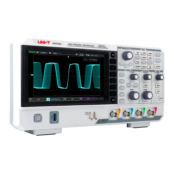
Display Key Panel Power switch Signal plate Figure 1 UPO1000X Series Block Diagram Power Supply The Power Supply board converts AC line voltage to secondary electric power supply for all internal circuits. Main Board The Main boards contain the following functions. -
Page 9: Keyboard And Display Screen
Service Manual UPO1000X Series Keyboard and Display Screen Keyboard contains read-keyboard knob and digital logic control, which can send information to the processor on the mainboard. The front panel also generates probe compensation output signals, provides USB ports and digital logic signal input interfaces on the front panel, and accommodates the main power switch. -
Page 10: Exterior Cleaning
Caution : Avoid the use of chemical cleaning agents which might damage the plastics used in this instrument. Use only deionized water when cleaning the front-panel buttons. Use a 75% isopropyl alcohol solution as a cleaner for cabinet parts. Before using any other type of cleaner, consult UNI-T Service Center or representative. -
Page 11: Return Instrument To Maintenance
• A complete description of the service request • Mark the address of the UNI-T Service Center and also your own return address on the shipping carton in two prominent locations. Removal and Replacement Procedure This section contains removal and replacement procedure, please see the replaceable module table and exploded view. -
Page 12: Removal And Replacement
Service Manual UPO1000X Series Removal and Replacement Remove Front Panel The following process is describes the removal and replacement of knob module on the front panel. Seven knob modules can be remove from the front panel. Precondition • Whenever you work on the insturment, you should wear grounded anti-static wristbands and foot bands, and use anti-static pads in a tested anti-static environment. - Page 13 Service Manual UPO1000X Series 2. Use T8 quincunx screwdriver to remove two screws from handle. 3. Remove two screws from the bottom of case and then to take off the rear panel. Instruments.uni-trend.com 13 / 31...
- Page 14 Service Manual UPO1000X Series 4. If you want to reinstall the rear panel, execute the steps in reverse. Use T8 quincunx screwdriver to fix the screw. Remove Rear Mdule The following process is describes the removal and replacement of rear module.
- Page 15 Service Manual UPO1000X Series 2. Use 9/16 inch open-end wrentch to remove two BNC nuts and washers. 3. Open the rear moduel and plug out the power cable from the mainboard. Instruments.uni-trend.com 15 / 31...
- Page 16 Service Manual UPO1000X Series 4. Put down the front module and rear module, and plug out FPC cable from the mainboard. 16 / 31 Instruments.uni-trend.com...
- Page 17 Service Manual UPO1000X Series 5. If you want to reinstall the rear panel, execute the steps in reverse. Remoce Power Module The following process is describes the removal and replacement of power module. Precondition • To prevent static damage to the components while working on the instrument, wear properly grounded anti-static wristbands and foot bands, and use anti-static pads in a tested anti-static environment.
- Page 18 Service Manual UPO1000X Series Plug out the power cable and fan’s power cable, use T10 quincunx screwdriver to move three screws on power module and take down the power module. If you want to reinstall the rear panel, execute the steps in reverse.
- Page 19 Service Manual UPO1000X Series • To prevent static damage to the components while working on the instrument, wear properly grounded anti-static wristbands and foot bands, and use anti-static pads in a tested anti-static environment. • Take down the rear panel.
- Page 20 Service Manual UPO1000X Series 3. If you want to reinstall the rear panel, execute the steps in reverse. Remove Front Panel The following process is describes the removal and replacement of front panel. Precondition To prevent static damage to the components while working on the instrument, wear properly grounded anti-static •...
- Page 21 Service Manual UPO1000X Series 2. Use T10 quincunx screwdriver to move nine screws and take down the front cover. 3. If you want to reinstall the rear panel, execute the steps in reverse. Remove Screen The following process is describes the removal and replacement of screen.
- Page 22 Service Manual UPO1000X Series 1. Use T10 quincunx screwdriver to move four screws. 2. Flip the screen and fixed support, plug out FPC cable between screen adapter board. 3. If you want to reinstall the rear panel, execute the steps in reverse.
- Page 23 Service Manual UPO1000X Series Remove Keyboard The following process is describes the removal and replacement of keyboard. Precondition • To prevent static damage to the components while working on the instrument, wear properly grounded anti-static wristbands and foot bands, and use anti-static pads in a tested anti-static environment.
-
Page 24: Troubleshooting
Service Manual UPO1000X Series 2. Use T10 quincunx screwdriver to move eleven screws. 3. If you want to reinstall the rear panel, execute the steps in reverse. Troubleshooting Caution:Before performing this or any other procedure in this manual, read the General Safety Summary and Service Safety Summary at the beginning of this manual. -
Page 25: Service Class
The information and procedure contains in this section can help you determine whether the instrument has problem. If is power failure, please send the instrument back to UNI-T Service Center for repair. Because the user cannot replace the internal electronic components or modules. - Page 26 Service Manual UPO1000X Series Start Connecting power supply Open power siwtch 1. Check fan’s connecting wire Whether Wheter fan is power key 2. Check fan’s power supply turning? is turns 3. Check whether fan is broken red? Confirm 1. Wheter power cable is connected...
- Page 27 Service Manual UPO1000X Series Check whethe Check keyboard’s keyboard’s LED is working connection properly? wire. Reinstall keyboard’s connection wire. Whether screen is display normally after 2 Check minutes? connection wire of display Send back to screen UNI-T Service Center Reinstall...
-
Page 28: After Maintenance
After Maintenance If the instrument cannot pass the performance verification test after remove and replace the power module, please send the instrument back to UNI-T Service Center for adjustement. Exploded View of Product The product is divided into three parts: front cover, product module and rear panel... - Page 29 Service Manual UPO1000X Series Table 4 Product’s Components Parts’ Name Description Front Panel Front panel contains the knobs Product’s module contains the front module and the rear module Produt’s Module Rear Panel Front Module Figure 4 Exploded View of Front Panel Table 5 Components of Front Panel Parts’...
- Page 30 Service Manual UPO1000X Series Display Screen HD screen Silicone Key Key and keyboard to realize man-machine interaction Keyboard Module Include keyboard and FPC cable Front Module Fixed mainboard, display screen, keyboard module Mainboard Core board Rear Module Figure 5 Exploded View of Rear Panel with Power and Fan Table 6 Components of Rear Panel Parts’...
- Page 31 Service Manual UPO1000X Series Power Module Power supply system for AC power input Rear Module Fixed interface Heat dissipation 31 / 31 Instruments.uni-trend.com...
Need help?
Do you have a question about the UPO1000X Series and is the answer not in the manual?
Questions and answers