
Related Manuals for Aaeon BOXER-8110AI


Summary of Contents for Aaeon BOXER-8110AI
- Page 1 BOXER-8110AI Compact Fanless Embedded AI@Edge Box PC User’s Manual 1 Last Updated: November 30, 2018...
- Page 2 AAEON assumes no liabilities resulting from errors or omissions in this document, or from the use of the information contained herein. AAEON reserves the right to make changes in the product design without notice to its users.
- Page 3 Acknowledgement All other products’ name or trademarks are properties of their respective owners. NVIDIA, the NVIDIA logo, and Jetson are trademarks of the NVIDIA Corporation Microsoft Windows is a registered trademark of Microsoft Corp. Intel, Pentium, Celeron, and Xeon are registered trademarks of Intel Corporation ...
- Page 4 Packing List Before setting up your product, please make sure the following items have been shipped: Item Quantity BOXER-8110AI Power Adapter (Option) Power Cord (Option) Wallmount bracket If any of these items are missing or damaged, please contact your distributor or sales representative immediately.
- Page 5 About this Document This User’s Manual contains all the essential information, such as detailed descriptions and explanations on the product’s hardware and software features (if any), its specifications, dimensions, jumper/connector settings/definitions, and driver installation instructions (if any), to facilitate users in setting up their product. Preface...
- Page 6 All cautions and warnings on the device should be noted. All cables and adapters supplied by AAEON are certified and in accordance with the material safety laws and regulations of the country of sale. Do not use any cables or adapters not supplied by AAEON to prevent system malfunction or fires.
- Page 7 As most electronic components are sensitive to static electrical charge, be sure to ground yourself to prevent static charge when installing the internal components. Use a grounding wrist strap and contain all electronic components in any static-shielded containers. If any of the following situations arises, please the contact our service personnel: Damaged power cord or plug Liquid intrusion to the device iii.
- Page 8 FCC Statement This device complies with Part 15 FCC Rules. Operation is subject to the following two conditions: (1) this device may not cause harmful interference, and (2) this device must accept any interference received including interference that may cause undesired operation.
- Page 9 China RoHS Requirements (CN) 产品中有毒有害物质或元素名称及含量 AAEON Embedded Box PC/ Industrial System 有毒有害物质或元素 部件名称 铅 汞 镉 六价铬 多溴联苯 多溴二苯醚 (Pb) (Hg) (Cd) (Cr(VI)) (PBB) (PBDE) 印刷电路板 ○ ○ ○ ○ ○ ○ 及其电子组件 外部信号 ○ ○ ○ ○ ○ ○...
- Page 10 China RoHS Requirement (EN) Poisonous or Hazardous Substances or Elements in Products AAEON Embedded Box PC/ Industrial System Poisonous or Hazardous Substances or Elements Hexavalent Polybrominated Polybrominated Component Lead Mercury Cadmium Chromium Biphenyls Diphenyl Ethers (Pb) (Hg) (Cd) (Cr(VI)) (PBB) (PBDE) PCB &...
-
Page 11: Table Of Contents
Table of Contents Chapter 1 - Product Specifications ..................1 Specifications ......................2 Product Notice ......................4 Chapter 2 – Hardware Information ..................5 Dimensions ....................... 6 Jumpers and connectors..................7 List of Jumpers ......................8 2.3.1 Setting Jumpers ................8 2.3.2 Auto Power Button (CN5) .............. - Page 12 Software & BSP ...................... 21 Preface...
-
Page 13: Chapter 1 - Product Specifications
Chapter 1 Chapter 1 - Product Specifications... -
Page 14: Specifications
Specifications System Nvidia Jetson TX2 Processor Module HMP Dual Denver 2/2 MB L2 + Quad ARM® Processor A57/2 MB L2 NVIDIA Pascal™,256 CUDA 4K x 2K 60 Hz Encode (HEVC) Video 4K x 2K 60 Hz Decode (12-Bit Support) System Memory ... - Page 15 Mechanical Wallmount Mounting 110mm(W) x 40mm(H) x 65mm(D) Dimension (W x H x D) Gross Weight 3.6 lb (1.6 kg) Net Weight 1.76 lb (0.8 kg) Environmental -4°F ~ 122°F(-20°C ~ 50°C) Operating Temperature -49°F ~ 176°F (-45°C ~ 80°C) Storage Temperature ...
-
Page 16: Product Notice
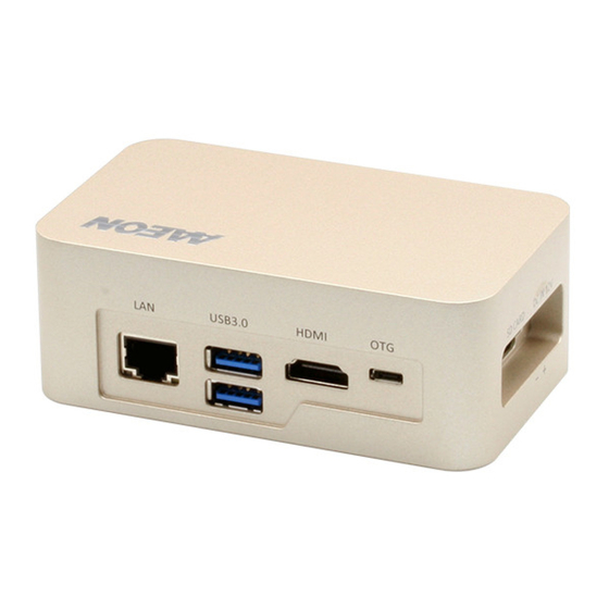
Product Notice OTG: OTG port is ideally for flashing image only. COM1: Support 1.8 meter length cable when baud rate 115200bps, and 15 meter cable when baud rate 9600bps. USB ports: USB ports are not support USB DVD ROM because of file system. Chapter 1 –... -
Page 17: Chapter 2 - Hardware Information
Chapter 2 Chapter 2 – Hardware Information... -
Page 18: Dimensions
Dimensions Chapter 2 – Hardware Information... -
Page 19: Jumpers And Connectors
Jumpers and connectors Chapter 2 – Hardware Information... -
Page 20: List Of Jumpers
List of Jumpers The board has a number of jumpers that allow you to configure your system to suit your application. The table below shows the function of each of the board's jumpers Label Function AT/ATX mode select 2.3.1 Setting Jumpers You configure your card to match the needs of your application by setting jumpers. -
Page 21: Auto Power Button (Cn5)
2.3.2 Auto Power Button (CN5) Disable(Default) Enable Function Open ATX Close AT (Default) Chapter 2 – Hardware Information... -
Page 22: List Of Connectors
List of Connectors The board has a number of connectors that allow you to configure your system to suit your application. The table below shows the function of each of the board's connectors Label Function RTC battery connector CN11 FAN connector USB 2.0 OTG CN10 TX2 Module connector... -
Page 23: Rtc Connector (Cn6)
2.4.1 RTC Connector (CN6) Signal Signal 2.4.2 Micro SD (CN5) Signal Signal SDCARD D3 SDCARD CMD SDCARD PWR(+3.3V) SDCARD CLK SDCARD D0 SDCARD D1 SDCARD D2 SDCARD CD 2.4.3 PWM FAN connector (CN11) Signal Signal FAN PWM FAN TACH Chapter 2 – Hardware Information... -
Page 24: Usb 2.0 Otg Connector (Cn9)
2.4.4 USB 2.0 OTG connector (CN9) Signal Signal VBUS USB1- USB1+ 2.4.5 Front Panel, UART for Debug and Exp. I/O (CN17) Signal Signal UART0 RX COM1 RX UART0 TX COM1 TX UART0 RTS COM1 RTS COM1 CTS UART0 CTS POWER BUTTON RESET RECOVERY SLEEP... -
Page 25: Tx2 Module Connector (Cn10)
2.4.6 TX2 Module connector (CN10) Chapter 2 – Hardware Information... -
Page 26: Canbus Connector (Db9 Female)
2.4.7 CANBUS connector (DB9 Female) Signal Signal CAN0 L CAN1 L CAN0 H CAN1 H 2.4.8 GPIO Port Connector (CN14) Signal Signal GPIO_EXP_P0 GPIO_EXP_P1 GPIO_EXP_P2 GPIO_EXP_P3 ACOK Chapter 2 – Hardware Information... -
Page 27: Hdmi Connector (Cn8)
2.4.9 HDMI connector (CN8) Signal Signal HDMI_DATA2_P HDMI_DATA2_N HDMI_DATA1_P HDMI_DATA1_N HDMI_DATA0_P HDMI_DATA0_N HDMI_CLK_P HDMI_CLK_N HDMI_SCL HDMI_SDA HDMI_PWR HDMI_HDP Chapter 2 – Hardware Information... -
Page 28: Usb3.0 Connector (Cn7)
2.4.10 USB3.0 connector (CN7) Signal Signal VBUS_1 VBUS_2 (A)D- (B)D- (A)D+ (B)D+ (A)SSRX- (B)SSRX- (A)SSRX+ (B)SSRX+ (A)SSTX- (B)SSTX- (A)SSTX+ (B)SSTX+ 2.4.11 Power in connector (CN2) Signal Signal PWR IN Chapter 2 – Hardware Information... -
Page 29: Com Port Connector (Male)
2.4.12 COM port connector (Male) RS-232 2.4.13 LAN (RJ-45) Port ACT/LINK SPEED Signal Signal MDI0+ MDI0- MDI1+ MDI1- MDI2+ MDI2- MDI3+ MDI3- Chapter 2 – Hardware Information... -
Page 30: Wall Mount Assembly
Wall Mount Assembly Chapter 2 – Hardware Information... -
Page 31: Chapter 3 - Os Flash Guide
Chapter 3 Chapter 3 – OS Flash guide... -
Page 32: Force Usb Recovery Mode
Force USB Recovery Mode To place system in Force USB Recovery Mode: 1. Power down the device. If connected, remove the AC adapter from the device. The device MUST be powered OFF, not in a suspend or sleep state. 2. Connect the Micro-B plug on the USB cable to the Recovery (USB Micro-B) Port on the device and the other end to an available USB port on the host PC. - Page 33 Software & BSP Please follow the steps below to install the test image. (1) Download Ubuntu_16.04_UB1604D.NV02.BOXER-8110AI.TB1.zip image. Please check with your local sales or FAE for the test image. The file name might be changed without notice. (2) Unzip Ubuntu_16.04_UB1604D.NV02.BOXER-8110AI.TB1.zip unzip Ubuntu_16.04_UB1604D.NV02.BOXER-8110AI.TB1.zip...
Need help?
Do you have a question about the BOXER-8110AI and is the answer not in the manual?
Questions and answers