
Related Manuals for Aaeon BOXER-8410AI


Summary of Contents for Aaeon BOXER-8410AI
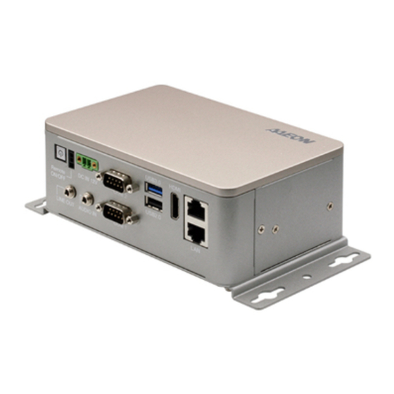
- Page 1 BOXER-8410AI Compact Fanless Embedded AI@Edge Box PC User’s Manual 1 Last Updated: March 31, 2020...
- Page 2 AAEON assumes no liabilities resulting from errors or omissions in this document, or from the use of the information contained herein. AAEON reserves the right to make changes in the product design without notice to its users.
- Page 3 Acknowledgement All other product name or trademarks are properties of their respective owners. HiSilicon, and the HiSilicon logo are trademarks of HiSilicon (Shanghai) ⚫ Technologies Co, LTD, and/or Huawei Technologies Co, LTD. ITE is a trademark of Integrated Technology Express, Inc. ⚫...
- Page 4 Packing List Before setting up your product, please make sure the following items have been shipped: Item Quantity BOXER-8410AI ⚫ Wallmount bracket ⚫ Screw Package ⚫ If any of these items are missing or damaged, please contact your distributor or sales representative immediately.
- Page 5 (if any), its specifications, dimensions, jumper/connector settings/definitions, and driver installation instructions (if any), to facilitate users in setting up their product. Users may refer to the product page at AAEON.com for the latest version of this document. Preface...
- Page 6 All cautions and warnings on the device should be noted. All cables and adapters supplied by AAEON are certified and in accordance with the material safety laws and regulations of the country of sale. Do not use any cables or adapters not supplied by AAEON to prevent system malfunction or fires.
- Page 7 As most electronic components are sensitive to static electrical charge, be sure to ground yourself to prevent static charge when installing the internal components. Use a grounding wrist strap and contain all electronic components in any static-shielded containers. If any of the following situations arises, please the contact our service personnel: Damaged power cord or plug Liquid intrusion to the device iii.
- Page 8 FCC Statement This device complies with Part 15 FCC Rules. Operation is subject to the following two conditions: (1) this device may not cause harmful interference, and (2) this device must accept any interference received including interference that may cause undesired operation.
- Page 9 China RoHS Requirements (CN) 产品中有毒有害物质或元素名称及含量 AAEON System QO4-381 Rev.A0 有毒有害物质或元素 部件名称 铅 汞 镉 六价铬 多溴联苯 多溴二苯 醚(PBDE) (Pb) (Hg) (Cd) (Cr(VI)) (PBB) 印刷电路板 × ○ ○ ○ ○ ○ 及其电子组件 外部信号 × ○ ○ ○ ○ ○ 连接器及线材 ○...
- Page 10 China RoHS Requirement (EN) Hazardous and Toxic Materials List AAEON System QO4-381 Rev.A0 Hazardous or Toxic Materials or Elements Component Name PCB and Components Wires & Connectors for Ext.Connections Chassis CPU & RAM HDD Drive LCD Module Optical Drive Touch Control...
-
Page 11: Table Of Contents
Table of Contents Chapter 1 - Product Specifications..................1 Specifications ......................2 Chapter 2 – Hardware Information ..................4 Dimensions ....................... 5 Jumpers and connectors..................7 List of Switches ......................8 2.3.1 COM RS-232 Mode Selection (SW5, SW6) ..........8 List of Connectors .................... - Page 12 Chapter 3 – OS Flash guide ....................26 Introduction ......................27 Hardware Pinout Definition ................. 27 Flash Image Steps ....................28 Preface...
-
Page 13: Chapter 1 - Product Specifications
Chapter 1 Chapter 1 - Product Specifications... -
Page 14: Specifications
Specifications System HiSilicon Hi3559A: Processor - ARM Cortex A73 x 2 cores - ARM Cortex A53 x 3 cores - ARM Cortex M7 Sensor Hub - 4 x DSP cores - 2 x NNIE multi-core heterogeneous processor ARM Mali 2 x G71 900MHz GPU Video HDMI 2.0 x 1 System Memory... - Page 15 System Internal Header USB 2.0 wafer x 2 RS-232 wafer x 2 Internal Button Reset Button Update Mode Button OS Support HiLinux Power Supply Power Requirement 12VDC-in with 2-pin terminal block Mechanical Mounting Wall mount kit (default) Dimensions (W x D x H) 150 mm(W) x 96 mm(D) x 56 mm(H) Gross Weight 2.20 lbs.
-
Page 16: Chapter 2 - Hardware Information
Chapter 2 Chapter 2 – Hardware Information... -
Page 17: Dimensions
Dimensions Chapter 2 – Hardware Information... - Page 18 I/O Closeup Chapter 2 – Hardware Information...
-
Page 19: Jumpers And Connectors
Jumpers and connectors CN22 CN13 CN81 CN20 CN41 CN40 CN33 CN65 CN79 CN78 CN80 A1.0_0_0 1907559106 CN68 CN16 CN23 CN24 CN9 CN70 CN19 SW3 CN35 Chapter 2 – Hardware Information... -
Page 20: List Of Switches
List of Switches The board has a number of switches that allow you to configure your system to suit your application. The table below shows the function of each of the board's switches Label Function COM1&2 RS-232 mode selection COM3&4 RS-232 mode selection 2.3.1 COM RS-232 Mode Selection (SW5, SW6) Chapter 2 –... -
Page 21: List Of Connectors
List of Connectors The board has a number of connectors that allow you to configure your system to suit your application. The table below shows the function of each of the board's connectors Label Function USB 2.0 (Header) CN13 Micro USB Connector CN16 HDMI Port CN19... -
Page 22: Usb 2.0 Header (Cn9/Cn24)
2.4.1 USB 2.0 Header (CN9/CN24) Pin Name Signal Type Signal Level USB2_DM DIFF USB2_DP DIFF 2.4.2 Micro USB Connector (CN13) Pin Name Signal Type Signal Level USB_DM0 DIFF USB_DP0 DIFF USB_ID +1.8V Chapter 2 – Hardware Information... -
Page 23: Hdmi Port (Cn16)
2.4.3 HDMI Port (CN16) Pin Name Signal Type Signal Level HDMI_TX2P DIFF HDMI_TX2N DIFF HDMI_TX1P DIFF HDMI_TX1N DIFF HDMI_TX0P DIFF HDMI_TX0N DIFF HDMI_TXCP DIFF HDMI_TXCN DIFF HDMI_CEC +3.3V HDMI_SCL HDMI_SDA HDMI_HOTPLUG Chapter 2 – Hardware Information... -
Page 24: Micro Sd Card Slot (Cn22)
2.4.4 Micro SD Card Slot (CN22) Pin Name Signal Type Signal Level DATA2 +1.8V DATA3 +1.8V +1.8V +3.3V +3.3V +1.8V DATA0 +1.8V DATA1 +1.8V DETECT +3.3V Chapter 2 – Hardware Information... -
Page 25: Usb 3.0 + Usb 2.0 Connector (Cn23)
2.4.5 USB 3.0 + USB 2.0 Connector (CN23) Pin Name Signal Type Signal Level +5VSB USB2_DM DIFF USB2_DP DIFF USB3_RXM DIFF USB3_RXP DIFF USB3_TXM DIFF USB3_TXP DIFF +5VSB USB2_DM DIFF USB2_DP DIFF Chapter 2 – Hardware Information... -
Page 26: Com Console Header Rs-232 (Wafer Box, Optional) (Cn33)
2.4.6 COM Console Header RS-232 (Wafer Box, Optional) (CN33) Pin Name Signal Type Signal Level Chapter 2 – Hardware Information... -
Page 27: Com1 + Com2 Connector Rs-232 (Cn35)
2.4.7 COM1 + COM2 Connector RS-232 (CN35) Pin Name Signal Type Signal Level Chapter 2 – Hardware Information... -
Page 28: Com3, Com4 Header Rs-232 (Wafer Box, Optional) (Cn40/41)
2.4.8 COM3, COM4 Header RS-232 (Wafer Box, Optional) (CN40/41) Pin Name Signal Type Signal Level Chapter 2 – Hardware Information... -
Page 29: Audio Wafer (Cn65)
2.4.9 Audio Wafer (CN65) Pin Name Signal Type Signal Level AC_IN_L AC_IN_R LINE_OUT_L LINE_OUT_R Chapter 2 – Hardware Information... -
Page 30: Dual Lan Connector (Cn68)
2.4.10 Dual LAN Connector (CN68) Pin Name Signal Type Signal Level MDIP0 DIFF MDIN0 DIFF MDIP1 DIFF MDIN1 DIFF MDIP2 DIFF MDIN2 DIFF MDIP3 DIFF MDIN3 DIFF +1.0V +1.0V MDIP0 DIFF MDIN0 DIFF MDIP1 DIFF MDIN1 DIFF MDIP2 DIFF MDIN2 DIFF MDIP3 DIFF... -
Page 31: Phoenix Connector Power Input (Cn70)
Pin Name Signal Type Signal Level MDIN3 DIFF +1.0V +1.0V 2.4.11 Phoenix Connector Power Input (CN70) Pin Name Signal Type Signal Level +12V 2.4.12 LAN0/LAN1 LED Signal Header (CN78/CN79) Pin Name Signal Type Signal Level LED_1000M +3.3V +3.3V +3.3V LED_100M +3.3V Chapter 2 –... -
Page 32: Sata Port (Cn80)
2.4.13 SATA Port (CN80) Pin Name Signal Type Signal Level SATA_TX+ DIFF SATA_TX- DIFF SATA_RX- DIFF SATA_RX+ DIFF 2.4.14 SATA Power (CN81) Pin Name Signal Type Signal Level +12V +12V Chapter 2 – Hardware Information... -
Page 33: System Update Mode Button (Sw1)
2.4.15 System Update Mode Button (SW1) Pin Name Signal Type Signal Level UPDATE_MODE +1.8V UPDATE_MODE +1.8V 2.4.16 System Reset Button (SW4) Pin Name Signal Type Signal Level WDG_RSTN +1.8V WDG_RSTN +1.8V Chapter 2 – Hardware Information... -
Page 34: Wall Mount Assembly
Wall Mount Assembly M3-Screw * 4 pcs Chapter 2 – Hardware Information... -
Page 35: 2.5" Sata Storage Drive Assembly
2.5” SATA Storage Drive Assembly Before beginning the installation procedure for the 2.5” SATA storage device, ensure your BOXER-8410AI system is shut down (not in sleep or standby mode) and disconnected from power source. Step 1: Remove the six screws from the bottom panel as shown in the figure. - Page 36 Step 2: Remove the four screws holding the 2.5” SATA drive carrier, and then remove the carrier from the system. STEP 2 = M3-Screw *4 pcs STEP 2 = M3-Screw *4 pcs Step 3: Place your 2.5” SATA storage device in the carrier and secure with four screws as shown.
- Page 37 Step 4: Following Steps 1 and 2 in reverse order, place the 2.5” SATA storage device and carrier assembly into the BOXER-8410AI system, securing with the four screws removed in Step 2. Then replace the bottom panel and secure with the six screws removed in Step 1.
-
Page 38: Chapter 3 - Os Flash Guide
Chapter 3 Chapter 3 – OS Flash guide... -
Page 39: Introduction
BOXER-8410AI PCBA removed from chassis (refer to as DUT) • Host PC with Windows 7 (Note: Process is only compatible with Windows 7) • OS image for BOXER-8410AI. Contact your AAEON representative or supplier • for image Get HiTool program to flash image •... -
Page 40: Flash Image Steps
Connect the 12V DC-IN with a power adapter and ensure it is pugged into a 12V power source. On host PC, extract/unzip the image and content files for BOXER-8410AI. You should see the following files. On host PC, run the HiTool program. - Page 41 Open the "Burn eMMC or UFS" tab. Fill out the partition table in HiTool. Refer to the README.txt file from the extracted BOXER-8410AI image for details. Click the "Burn" button in HiTool. Chapter 3 – OS Flash guide...
- Page 42 On the DUT, press and release the Power Button. Next, press and hold the Update Button. While holding the Update Button, press and release the Reset Button. Chapter 3 – OS Flash guide...
- Page 43 Keep holding the Update Button for 2 more seconds after pressing the Reset Button, then release. HiTool should display burning process in progress. Chapter 3 – OS Flash guide...
Need help?
Do you have a question about the BOXER-8410AI and is the answer not in the manual?
Questions and answers