Table of Contents
Advertisement
Quick Links
Assembly Instructions
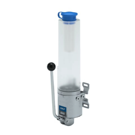
Single-piston pump of the
ACP/MCP type series
Pneumatically/manually operated piston pump for single-line systems
Creation date:
06.08.2020
Document no.:
951-170-237-EN
Version:
01
Read this manual before
installing or commissioning the
product and keep it at hand for
later reference!
Advertisement
Table of Contents

Subscribe to Our Youtube Channel
Related Manuals for SKF LINCOLN ACP Series


Summary of Contents for SKF LINCOLN ACP Series
- Page 1 Assembly Instructions Single-piston pump of the ACP/MCP type series Pneumatically/manually operated piston pump for single-line systems Creation date: 06.08.2020 Document no.: 951-170-237-EN Version: Read this manual before installing or commissioning the product and keep it at hand for later reference!
- Page 2 Germany Berlin Manufacturer: SKF Lubrication Systems Germany GmbH, Motzener Straße 35/37, DE - 12277 Berlin Note regarding manually driven MCP piston pumps: The manually driven MCP piston pumps do not fall within the scope of the machinery directive (2006/42/EG). Despite this, the manually driven MCP pump has been designed, manufactured and tested taking into account all relevant factors that influence its safety.
- Page 3 Table 1 Annex to the declaration of incorporation No.: Basic safety and health requirements Applicable: Complied with: 1.2.4.3 Emergency stop 1.2.4.4 Assembly of machinery 1.2.5 Selection of control or operating modes 1.2.6 Failure of the power supply Protection against mechanical hazards 1.3.1 Risk of loss of stability 1.3.2...
- Page 4 Table 1 Annex to the declaration of incorporation No.: Basic safety and health requirements Applicable: Complied with: 1.7.4.1 General principles for the drafting of instructions 1.7.4.2 Contents of the instructions 1.7.4.3 Sales literature The product is basically designed for the use of harmless media. The operator must check whether the lubricant used has certain hazardous effects (e.g.
-
Page 5: Masthead
Training www.skf.com/lubrication We conduct detailed training in order to enable maximum safety and efficiency. We recommend taking advantage of this training. Berlin Plant For further information, contact your authorized SKF dealer or Motzener Strasse 35/37 the manufacturer. 12277 Berlin Germany Tel. -
Page 6: Table Of Contents
6.5 Compressed air connection (pneumatically operated Table of contents single-piston pumps) ..............21 6.6 Lubrication line connection ..........22 Masthead ..................... 5 6.7 Laying of the lubrication lines ..........22 Table of contents ................6 7. First start-up ................24 Safety alerts, visual presentation, and layout ........ -
Page 7: Safety Alerts, Visual Presentation, And Layout
1. Instruction steps: These indicate a chronological sequence Safety alerts, visual of instruction steps. The numbers of the steps are in bold and are followed by a period. If a new activity follows, the presentation, and layout numbering starts again at “1.” –... -
Page 8: Safety Instructions
Unauthorized product modifications and changes are therefore prohibited. Only original SKF spare parts and SKF accessories may be used. Operator Any unclear points regarding proper condition or correct A person who is qualified by training, knowledge and experience assembly/operation must be clarified. -
Page 9: Referenced Documents
substances and mixtures that are marked with hazard NOTE pictograms GHS01-GHS06 and GHS08. In accordance with the results of the workstation risk • Use to supply, convey, or store Group 1 fluids classified as assessment, additional labels (e.g., warnings, safety signs, hazards as defined in the Pressure Equipment Directive prohibition signs, or labels in accordance with CLP/GHS) are (2014/68/EU) Article 13 (1) a). -
Page 10: Emergency Shutdown
pressure gauges, min./max. markings, or oil level gauges must 1.13 Emergency shutdown be clearly visible. Observe the mounting position requirements. This is done by a course of action to be defined by the operator. Drill required holes only on non-critical, non-load-bearing parts of the operator's infrastructure. -
Page 11: Residual Risks
1.16 Residual risks Table 2 Residual risks Residual risk Possible in life cycle Prevention/ remedy People slipping due to floor G H K • Exercise caution when connecting the product's contamination with spilled or leaked hydraulic connections lubricant. • Bind and remove leaked or spilled lubricant immediately with a suitable agent •... -
Page 12: Lubricants
• Always use SKF lubrication greases, if possible. These are optimally suited for use in lubrication systems. • Do not mix lubricants. This may have unforeseeable effects on... -
Page 13: Overview, Functional Description
3. Overview, functional description Fig. 3 Design and function of the pump variants... -
Page 14: Construction Designs
Table 3 Legend Illustrations 3 and 4 Explanation: Explanation: Version for fluid grease (without oil filter), manually Oil filter (only in the version for oil supply) operated Version for oil, pneumatic drive Hand lever Compressed air connection G ¼ x Lubricant reservoir Filling aperture with cap Float switch (only in the version for oil supply) -
Page 15: Design
Fig. 5 NOTE Should the documentation not be available, you may request it from SKF Lubrication Systems Germany GmbH directly. 3.2 Design Figure 3 shows the basic design of the single-piston pump ACP respectively MCP. On the pump housing (Fig. 3/3) there is the lubricant reservoir (Fig. -
Page 16: Filling Level Monitoring
3.5 Filling level monitoring Single-piston pump for fluid grease supply Single-piston pump for oil supply The filling level monitoring is realized by means of a capacitive The filling level monitoring is realized by means of a float switch. filling-level switch. The capacitive filling-level switch is The electrical connection of the float switch is made via a 4-pin connected via a 4-pin quarter-turn type plug M8x1. - Page 17 Table 5 Technical data: Designation Values: Compressed air connection (pneumatically operated single-piston pumps) G ¼ x 12 mm in the bottom of the housing Connection Max. primary pressure 10 bar Min. primary pressure 3.5 bar Electrical connection (single-piston pumps with filling level monitoring) Float switch: •...
-
Page 18: Type Identification Code
4.1 Type identification code A C P 1 5 - 1 W A 1 1 X X - U 1 0 Type designation/type of actuation: ACP: Pneumatically driven MCP: Manually driven (hand operated) Type designation / output: 15: 15 cm³/stroke Version index: Version Warning switch for pre-warning:... -
Page 19: Delivery, Returns, Storage
5.4 Storage temperature range 5. Delivery, returns, storage For parts not filled with lubricant, the permitted storage 5.1 Delivery temperature is the same as the permitted ambient temperature range (see “Technical data”). After receipt of the shipment, it must be inspected for any 5.5 Storage conditions for products filled shipping damage and for completeness according to the shipping documents. -
Page 20: Assembly
documentation. Dimensions and positions of the fixing bores on 6. Assembly the connecting flange can be taken also by measurement. The single-piston pump is fixed to the intended installation 6.1 General information place by means of suitable fastening material (e.g. screws, washers, nuts). -
Page 21: Capacitive Filling-Level Switch (Single-Piston Pump For Fluid Grease Supply)
6.4.3 Capacitive filling-level switch (single- Table 6 piston pump for fluid grease supply) Colour marking of the cable cores The capacitive filling-level switch for the filling level monitoring Abbreviation Colour of a single-piston pump for fluid grease supply can be operated <Content>... -
Page 22: Lubrication Line Connection
Lubricants may pollute ground and waters. occurring particularly in single-line piston metering device Lubricants have to be handled and disposed of systems, there may be used SKF solderless lubrication line properly. Observe the regional laws and fittings (double or single cone rings). - Page 23 < CAUTION Lubricants leaking from leaky lubrication lines Risk of slipping and injury Centralized lubrication systems must be absolutely leakproof. Leaking lubricant is hazardous due to the risk of slipping and injury. During assembly, operation, maintenance and repair of centralized lubrication systems watch out for leaking lubricant.
-
Page 24: First Start-Up
2. Lubricant filling via filler lid is also possible with adequate 7. First start-up equipment (e.g. barrel pump or similar) 3. Then vent the single-piston pump and the centralized lubrication system NOTE Before commissioning the single-piston pump check all pneumatic and, if existing, electrical connections. 7.2 Adjustment of the capacitive filling level switch (single-piston pumps for After assembly of the single-piston pump and laying the... -
Page 25: Vent Centralized Lubrication System
Table 7 Functions of the electronic filling level switch Designation: Explanation: Version: Display: Empty adjustment The empty adjustment readjusts Empty the reservoir up to about LED flashes slowly. the switch. The switch is 20 mm below the sensor. • Normally open contact: readjusted to the empty lubricant •... -
Page 26: Operation
2. Disassemble the main lubrication line from the main metering 8. Operation device. Operate the single-piston pump until bubble-free lubricant escapes from the main line. Then mount the main 8.1 General notes lubrication line again. 3. Disassemble the secondary lubrication lines from the main During operation the following notes should be observed to metering device. -
Page 27: Maintenance And Repair
WARNIG accidentally, inside cleaning of the product will be required. To Serious injury from contact with or inhalation do so please contact the Service Department of SKF Lubrication of hazardous substances Systems Germany GmbH. Disassembly of the product or of single components of the product within the legal warranty period is not admissible and Wear personal protective equipment. -
Page 28: Faults, Causes, And Remedies
The following table 9gives an overview of possible malfunctions and their causes. If it is not possible to remedy the malfunction, During operation centralized lubrication systems please contact the Service Department of SKF Lubrication are pressurized. Therefore, centralized lubrication Systems Germany GmbH. -
Page 29: Shutdown, Disposal
The product can also be returned for disposal to SKF Lubrication Systems Germany GmbH, in which case the customer is responsible for reimbursing the costs incurred. -
Page 30: Spare Parts
14. Spare parts Spare parts may be used exclusively for replacement of identical defective parts. Modifications with spare parts on existing products are not allowed. Table 10 Spare parts Designation Part number Fig. Filling level switch assy. 24-2540-2955 Filling strainer PA/NYLON 44-1874-2018 KIT replacement reservoir 0.5 ACP/MCP (shown on the right) 5112-00000001... - Page 31 5112-00000006 NOTE For further technical data see the following brochures: • Electrical push-in type connectors (brochure no. 1-1730-EN) • Lubricant metering device for SKF MonoFlex systems (brochure no. 1-5001-EN) • Transport of lubricants in centralized lubrication systems (brochure no. 1-9201-EN)
- Page 32 ® SKF is a registered trademark of the SKF Group. ™ eLube is a trademark of the SKF Group. © SKF Group 2020 Reprint or reproduction of the contents of this information - even in part - is permitted only with SKF's prior written consent.
Need help?
Do you have a question about the LINCOLN ACP Series and is the answer not in the manual?
Questions and answers