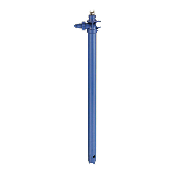
Finish Thompson PF Series Operation-Installation-Parts Manual

Finish Thompson PF Series Operation-Installation-Parts Manual

Advertisement

Quick Links

PF SERIES PUMPS
PFM, PFP, PFV
OPERATION, INSTALLATION & PARTS MANUAL
Serial Number 178923 & lower

Advertisement

Table of Contents
loading

Summary of Contents for Finish Thompson PF Series

  • Page 1 PF SERIES PUMPS PFM, PFP, PFV OPERATION, INSTALLATION & PARTS MANUAL Serial Number 178923 & lower...
  • Page 3: Table Of Contents

    Introduction This manual pertains to the PF Series, specifically the PFP, PFM, and PFV plastic drum pumps. Finish Thompson Inc. thanks you for choosing our products. We believe the use of our products will be fully satisfactory. When properly installed and operated, your Finish Thompson motor and pump will provide long, trouble-free service; therefore, please read this manual carefully before carrying out any operations on the pump/motor unit.
  • Page 4: Warranty, General Terms & Conditions

    The warranty of the products shall be valid for a period of 12 months from the date of delivery, under the condition that notice of the alleged defect to the products or parts thereof be given to Finish Thompson, Inc. within the term of 8 days from the discovery.
  • Page 5: Safety

    The personnel in charge of the installation, the operation, and the maintenance of the pump must be qualified and able to per- form the operations described in this manual. Finish Thompson, Inc. shall not be held responsible for the training level of personnel and for the fact that they are not fully aware of the contents of this manual.
  • Page 6: Pump Specifications

    PUMP SPECIFICATIONS MODEL PFM MODEL PFP MODEL PFV Outer Tube Diameter 2” (51 mm) 2” (51 mm) 2” (51 mm) Discharge Spout Variable orifice barb fitting Variable orifice barb fitting Variable orifice barb fitting Discharge Thread 1-1/4” NPSM 1-1/4” NPSM 1-1/4”...
  • Page 7: Installation

    INSTALLATION & MAINTENANCE INSTRUCTIONS Installation 1. Remove the drum pump from its packaging and inspect for shipping damage. 2. Turn the pump coupling to verify there is no binding. 3. Verify the housing cover (item 21) is on tight (it has a left hand thread). 4.
  • Page 8: Inspection

    Inspection 1. Check the housing cover (item 21), the impeller (item 20), and the impeller housing (item 18) for wear, rub- bing, or damage from foreign objects. Replace if damaged. Note: The double impeller design of this pump is dependant on the impeller working correctly. Any damage to the impeller can cause pump failure.
  • Page 9: Exploded View

    PFM/PFP/PFV SPARE PARTS EXPLODED VIEW...
  • Page 10: Design Change

    Impeller Housing change - PFM, PFP, PFV Series Old Style Impeller Item Description PFM/PFP (Polypropylene) (PVDF) PF27 intake tube M100005-1 M100005-5 PF40 intake tube M100005-3 M100005-6 PF48 intake tube M100005-4 M100005-7 PF60 intake tube M100005-8 M100005-12 PF72 intake tube M100005-11 M100005-10 PF27 upper inner tube M100050-1...
  • Page 11: Pump Tube Spare Parts List

    PUMP SPARE PARTS LIST PART NUMBER ITEM DESCRIPTION MODEL PFM MODEL PFP MODEL PFV COUPLING INSERT J100014 J100014 J100014 COUPLING HALF J100012 J100012 J100012 BEARING ASSEMBLY A101110 A101110 A101110 LIP SEAL 1/4” FKM 107592 107592 107592 NEW STYLE PUMP HEAD POLYPROPYLENE 107755-1 107755-1...
  • Page 12 PART NUMBER ITEM DESCRIPTION MODEL PFM MODEL PFP MODEL PFV DISCHARGE O-RING J100991 J100991 J100991 EPDM J102378 J102378 J102378 PERLAST 107017 107017 107017 SPOUT 1” BARB (STANDARD) M100028-1 M100028-1 M100028-2 3/4” BARB (OPTIONAL) 105439-1 105439-1 105439 1” MNPT (OPTIONAL) 106599 106599 106599-1 DISCHARGE NUT...

Table of Contents