Advertisement
ASSEMBLY
Unpack pump from carton and check for shipping damage.
PUMPS WITH MOTOR
No assembly required. Simply unpack the pump and motor and
examine for any shipping damage. If damage is detected, save
the packaging and notify the carrier immediately.
Remove the shipping plugs from the suction and discharge of
the pump and proceed to the "Installation Requirements" sec-
tion of these instructions.
PUMPS WITHOUT MOTORS
1. Unpack the pump and examine for any shipping damage.
If damage is detected, save the packaging and notify the
carrier immediately. Use the "Supplied and Optional Parts"
section of these instructions to verify that all items have
been received.
2. Prepare to install the pump onto the motor.
a. Remove the protective shroud (Item 22) from the motor
adapter (item 6).
b. Ensure that the set screws in shaft adapter (Item 20)
are loosened to avoid interference when installing.
c. Coat the motor shaft with an anti-seize compound prior
to installation.
3. Properly adjust the spacing between the impeller (item 3)
and the housing cover (item 2).
NOTE: Proper spacing of the Impeller to the housing cover
is critical for performance and to avoid damage to pump
components. A .050" gap is required.
a. Slide the shaft adapter onto the motor shaft until the
impeller is tight against the inside of the housing
cover (look through the pump's discharge to verify).
Make sure that the shaft adapter's set screws do not
line up into the motor shaft's key way.
b. Temporarily bolt the motor adapter to the motor, placing
shims (flat washer - item 10) between the motor
adapter and the motor using two hex-head cap screws
(Item #11) 180° apart (see Figure 1).
c. Tighten the four set screws from the shaft adapter onto
the motor shaft.
d. Remove the two temporary hex-head cap screws and
shim washers.
4. Pull the motor adapter flush against the motor face. Install
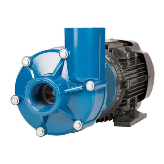
GP11 SERIES Sealed
Non-Metallic Centrifugal Pumps
Installation and
Maintenance Instructions
5.
6.
7.
INSTALLATION
MOUNTING
Motor or base plate must be securely fastened.
PIPING
•
•
•
•
•
•
•
PUMPS WITH COOLING (PRESSURE) COLLARS
A cooling collar provides a water flush to the pump's seal. This
is necessary when pumping hot liquids or liquids that tend to
build up or crystallize around the seal faces. If your pump is
supplied with a cooling collar, proper water flow and pressure
are critical to the operation of the pump.
1.
2.
1
Figure 1
four hex-head cap screws and flat washers through the
motor adapter and into the motor and tighten.
Verify there is a .050" gap between the impeller and hous-
ing cover by looking into the discharge of the pump.
Reinstall the protective shroud.
Install the pump into your system according to the "Instal-
lation Requirements" section of these instructions.
Always support the piping near the pump to minimize
stress and strain on the pump's casing.
Minimize frictional losses by increasing the piping size by
one diameter.
Use a minimal number of bends, keeping any bends at
least a distance of ten pipe diameters away from the pump.
Install valves on the suction and discharge lines. Place the
valves within a distance of ten pipe diameters away from
the pump.
Ensure that the piping is leak free.
Position the pump as close to the liquid source as possible.
Maintain a flooded suction at all times.
Plumb a water supply to the cooling collar. Use 1/8" NPT
threaded holes for the water inlet and drain lines. Either
hard pipe or flexible tubing is suitable.
Adjust the water flow and pressure of the flush/cooling
water BEFORE starting the pump.
Advertisement
Table of Contents

Subscribe to Our Youtube Channel
Related Manuals for Finish Thompson GP11 Series


Summary of Contents for Finish Thompson GP11 Series
- Page 1 GP11 SERIES Sealed Non-Metallic Centrifugal Pumps Installation and Maintenance Instructions ASSEMBLY Unpack pump from carton and check for shipping damage. PUMPS WITH MOTOR No assembly required. Simply unpack the pump and motor and Figure 1 examine for any shipping damage. If damage is detected, save four hex-head cap screws and flat washers through the the packaging and notify the carrier immediately.
-
Page 2: Operation
• For pumps with bellows or multi-spring seals, supply d. Jog the motor (allow it to run for only one to two sec- one to two gallons water flow per hour at 1 - 2 psi. onds) and observe the rotation of the motor fan. Refer to the directional arrow on the pump if needed. - Page 3 emulsion or soapy water. NOTE: For pumps using a 56C/145TC or motor adapter, leave the shaft adapter secured to the motor shaft. b. Carefully slide the housing cover over the Impeller’s shaft. The side of the housing cover with the pressed- Remove the seal for inspection.
-
Page 4: Troubleshooting
3. Install the rotating faces and cooling collar to the motor b. Align the motor adapter so that the access hole is adapter. straight up. a. Carefully slide the housing cover over the impeller’s c. Bolt the motor adapter to the motor using the hex-head shaft. - Page 5 Item Description Part No. Item Description Part No. Impeller Housing Lock Washer Polypropylene NPT M100101-1 NEMA 56C - stainless steel (4 required) J100115 PVDF NPT M100101-2 IEC 80 frame - stainless steel (4 required) J100672 Polypropylene BSP 108173-1 IEC 90 frame - stainless steel (4 required) J102282 PVDF BSP 108173-2...
-
Page 6: Warranty Registration
The manufacturer accepts no responsibility for product dam- For further information, contact Finish Thompson Inc. or your local distribu- age or personal injuries sustained when the product is modified in any tor. -
Page 7: Eu Declaration Of Conformity
EU Declaration of Conformity Finish Thompson Inc. hereby declares that the following machine(s) fully comply with the applicable health and safety requirements as specified by the EU Directives listed. The product may not be taken into service until it has been established that the drive motor for the centrifugal pump complies with the provisions of all relevant EU Directives.
Need help?
Do you have a question about the GP11 Series and is the answer not in the manual?
Questions and answers