Table of Contents
Advertisement
Quick Links
Product manual
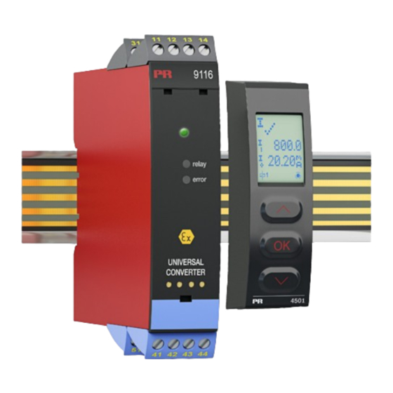
9116-EMP
Universal converter,
EMPHASIS-assessed
E M P H A S I S
a s s e s s e d
T E M P E R AT U R E
|
I . S . I N T E R FA C E S
No. 9116 - EMP V10 9 - UK
Produc t ver sion: 9116 - 0 03
|
CO M M U N I C AT I O N I N T E R FA C E S
|
M U LT I F U N C T I O N A L
|
I S O L AT I O N
PERFORMANCE
MADE
SMARTER
|
D I S P L AY
Advertisement
Table of Contents

Related Manuals for PR electronics 9116-EMP


Summary of Contents for PR electronics 9116-EMP
- Page 1 PERFORMANCE MADE SMARTER Product manual 9116-EMP Universal converter, EMPHASIS-assessed E M P H A S I S a s s e s s e d T E M P E R AT U R E I . S . I N T E R FA C E S...
- Page 2 6 Product Pillars to meet your every need Individually outstanding, unrivalled in combination With our innovative, patented technologies, we make signal conditioning smarter and simpler. Our portfolio is composed of six product areas, where we offer a wide range of analog and digital devices covering over a thousand applications in industrial and factory automation.
-
Page 3: Table Of Contents
Document history ..................9116-EMP - Product version 9116-003... -
Page 4: Warning
General mounting, wire connection and disconnection. Troubleshooting the device. Repair of the device and replacement of circuit breakers must be done by PR electronics A/S only. Warning Do not open the front plate of the device as this will cause damage to the connector for the display / programming front PR 4500. -
Page 5: How To Demount System 9000
To the extent the instructions in this manual are not strictly observed, the custom er cannot advance a demand against PR electronics A/S that would otherwise exist according to the concluded sales agreement. How to demount system 9000 Picture 1: By lifting the bottom lock, the device is detached from the DIN rail. 9116-EMP - Product version 9116-003... -
Page 6: Advanced Features
Monitoring of error events and cable breakage via the individual status relay and/or a collective electronic signal via the power rail. • The 9116-EMP has been designed, developed and certified for use in SIL 2 applications according to the requirements of IEC 61508. •... -
Page 7: Applications - 9116Ax-Emp
N.C. Device status Same power rail as above Zone 0, 1, 2, 20, 21, 22, M1 & Cl. I/II/III, Div. 1 Zone 2 & Cl. 1, Div. 2, gr. A-D gr. A-G or Safe Area 9116-EMP - Product version 9116-003... -
Page 8: Applications - 9116Bx-Emp
N.C. Device status Same power rail as above Zone 0, 1, 2, 20, 21, 22, M1 & Cl. I/II/III, Div. 1 Zone 2 & Cl. 1, Div. 2, gr. A-D gr. A-G or Safe Area 9116-EMP - Product version 9116-003... -
Page 9: Pr 4500 Display / Programming Front
Application • Communications interface for modification of operational parameters in 9116-EMP. • Can be moved from one 9116-EMP device to another and download the configuration of the first unit to subsequent units. • When mounted in the process, the display shows process values and device status. -
Page 10: Order
Max. power dissipation is the maximum power dissipated by the device. If the 9116-EMP is used with the PR 4500, then add 40 mW to the max. power dissipation and 70 mW to the max. required power for each device with the PR 4500. - Page 11 2-wire supply (terminal 54...52) ......21.4...16.5 VDC / 0...20 mA 9116-EMP - Product version 9116-003...
- Page 12 Input resistance ........Nom. >10 MΩ 9116-EMP - Product version 9116-003...
- Page 13 Max. AC power ........62.5 VA / 32 W of span = of the currently selected measurement range 9116-EMP - Product version 9116-003...
- Page 14 EAC Ex ......... . RU C-DK.HA65.B.00355/19 Functional Safety: SIL 2 Certified & Fully Assessed acc. to IEC 61508 9116-EMP - Product version 9116-003...
-
Page 15: Configuration Of Sensor Error Check
Sensor broken or SE.BR wire resistance too high LIN.R For Lin. R_0%≥ app. 18 Ω SE.SH Sensor shorted Sensor broken or SE.BR wire resistance too high TEMP Pt100 to Pt1000 and Ni50 to Ni1000 SE.SH Sensor shorted 9116-EMP - Product version 9116-003... -
Page 16: Error Indications
- this is acknowledged (stopped) by pushing the 3 button. Error is acknowledged by resetting the device power. Error can be disregarded by selecting input type different than TC. *** Error is acknowledged by stepping through the basic setup. 9116-EMP - Product version 9116-003... -
Page 17: Connections
RTD, 3- / 4-wire CJC sensor CJC connector * Order separately: Resistance, CJC connector 5910 / Resistance, 2-wire 3- / 4-wire Potentiometer 5910Ex 2-wire transmitter Current Voltage Outputs: Current 2-wire transmitter (Active output) (Passive output) Relay N.O. 9116-EMP - Product version 9116-003... -
Page 18: Block Diagram
Device status, Green Supply +24 VDC Relay status, Yellow Ch. status, Red FLASH Status relay N.C. Status relay N.C. RTD, conn. wires Supply output Input Gnd. Volt- Current Relay N.O. Relay output Relay N.O. 9116 9116-EMP - Product version 9116-003... -
Page 19: Signal Error And Cable Fault Indications Without Display Front
Output relay energized Flashing Energized Open Output relay energized Closed Flashing Flashing De-energized w. wire short/break (if activateded) Output relay de-energized Closed Flashing Flashing De-energized w. wire short/break (if activateded) Output relay de-energized Flashing Energized Open 9116-EMP - Product version 9116-003... -
Page 20: Configuration / Operating The Function Keys
In general When configuring the 9116-EMP, you will be guided through all parameters and you can choose the settings which fit the application. For each menu there is a scrolling help text which is automatically shown in line 3 on the display. - Page 21 You can choose between UK, DE, FR, IT, ES, SE and DK. Power rail: In the menu ”RAIL” you can choose if sensor errors are transmitted to the central surveillance in the PR 9410 power control unit. Safety Integrity Level (SIL): See Safety Manual for details. 9116-EMP - Product version 9116-003...
- Page 22 Txt 6 TC.Lr TC.W5 TC.W3 TC.U TC.T TC.S CONN TC.R TC.N TC.L TC.WK TC.J TC.E Continued on the page Routing diagram ADV.SET TC.K ADV.SET SENSOR TC TYPE Txt 2 Txt 10 Txt 18 Txt 31 9116-EMP - Product version 9116-003...
-
Page 23: Routing Diagram
DISP.HI REL.UNI Continued on the next page Txt 13 Txt 14 Txt 15 Selectable UNITS: mm/s m3/min m/min m3/h in/s l/min ft/s gal/min in/min gal/h mils ft/min in/h mbar ft/h m/s2 [blank] UNIT Txt 9 9116-EMP - Product version 9116-003... - Page 24 Not available on PR 4500 if SIL-locked. Not valid for these input signals: 0...20 mA and voltage. Only for 4512 devices with serial no. from 211065001 and for 4511 devices with serial no. from 211001001. 9116-EMP - Product version 9116-003...
-
Page 25: Routing Diagram, Advanced Settings (Adv.set)
3 to return to the default state 1.0. 23.0 SETUP EN.SIM REL.SIM Txt 43 Txt 51 Txt 53 Txt 52 0000 LOCK 9999 OPEN Verify SIL configuration 0000 LOCK SETUP EN.SIL NEW.PAS CONFIG SIL.OK Txt 43 Txt 64 Txt 55 Txt 66 9116-EMP - Product version 9116-003... -
Page 26: Help Text Overview
Write a 5-character channel TAG [48] Select TC-U sensor type Show Analog output value in display Show TAG on display Select TC-W3 sensor type Alternate shown information in display Select TC-W5 sensor type Select TC-Lr sensor type 9116-EMP - Product version 9116-003... - Page 27 [88] Flash memory error - chek configuration [89] Invalid configuration type or version [90] Hardware error [91] CJC sensor error - check device temperature [92] CJC error - check CJC connector block [93] No communication 9116-EMP - Product version 9116-003...
-
Page 28: Graphic Depiction Of Window
Graphic depiction of window 9116-EMP - Product version 9116-003... -
Page 29: Graphic Depiction Of Setpoint
Graphic depiction of setpoint Input ON delay signal OFF delay Setpoint (increasing) Hysteresis Time Relay On Closed Relay contact (N.O.) Open 9116-EMP - Product version 9116-003... -
Page 30: Iecex Installation Drawing
For Installation in Zone 2 the following must be observed. The 4501 programming module is to be used solely with PR electronics modules. It is important that the module is undamaged and has not been altered or modified in any way. Only 4501 modules free of dust and moisture shall be installed. - Page 31 For installation on Power Rail in Zone 2, only Power Rail type 9400 supplied by Power Control Unit type 9410 (Type Examination Certificate KEMA 07ATEX0152 X) is allowed. Revision date: Version Revision Prepared by: Page: 2018-03-01 V8 R0 9116-EMP - Product version 9116-003...
- Page 32 Term. 54-52; 51-52 21.4 V 0.16 μF 4 mH 54 μH/Ω 93 mA 1.13 μF 16 mH 218 μH/Ω 650 mW 4.15 μF 32 mH 436 μH/Ω Revision date: Version Revision Prepared by: Page: 2018-03-01 V8 R0 9116-EMP - Product version 9116-003...
- Page 33 Lo/Ro Term. 52-51, 51-52 16.6 V 0.4 μF 100 mH 25mH/Ω 0.2 mA 2.3 μF 100 mH 100mH/Ω 0.8 mW 9.5 μF 100 mH 200mH/Ω Revision date: Version Revision Prepared by: Page: 2018-03-01 V8 R0 9116-EMP - Product version 9116-003...
- Page 34 9410 (Type Examination Certificate IECEx KEM 08.0025X) is allowed. The 4501 programming module is to be used solely with PR electronics’ modules. It is important that the module is undamaged and has not been altered or modified in any way.
-
Page 35: Atex Installation Drawing
For installation in Zone 2 the following must be observed. The 4501 programming module is to be used solely with PR electronics’ modules. It is important that the module is undamaged and has not been altered or modified in any way. - Page 36 For installation on Power Rail in Zone 2, only Power Rail type 9400 supplied by Power Control Unit type 9410 (Type Examination Certificate KEMA 07ATEX0152 X) is allowed. Revision date: Version Revision Prepared by: Page: 2018-03-01 V8 R0 9116-EMP - Product version 9116-003...
- Page 37 Term. 54-52; 51-52 21.4 V 0.16 μF 4 mH 54 μH/Ω 93 mA 1.13 μF 16 mH 218 μH/Ω 650 mW 4.15 μF 32 mH 436 μH/Ω Revision date: Version Revision Prepared by: Page: 2018-03-01 V8 R0 9116-EMP - Product version 9116-003...
- Page 38 Lo/Ro Term. 52-51, 51-52 16.6 V 0.4 μF 100 mH 25mH/Ω 0.2 mA 2.3 μF 100 mH 100mH/Ω 0.8 mW 9.5 μF 100 mH 200mH/Ω Revision date: Version Revision Prepared by: Page: 2018-03-01 V8 R0 9116-EMP - Product version 9116-003...
- Page 39 9410 (Type Examination Certificate KEMA 07ATEX0152 X) is allowed. The 4501 programming module is to be used solely with PR electronics’ modules. It is important that the module is undamaged and has not been altered or modified in any way.
-
Page 40: Fm Installation Drawing
For Installation in Zone 2 / Division 2 the following must be observed. The 4501 programming module is to be used solely with PR electronics modules. It is important that the module is undamaged and has not been altered or modified in any way. Only 4501 modules free of dust and moisture shall be installed. - Page 41 Warning: Do not mount or remove modules from the Power Rail when an explosive gas mixture is present. Revision date: Version Revision Prepared by: Page: 2019-04-04 V7 R0 9116-EMP - Product version 9116-003...
- Page 42 IIC or A,B Io, Isc 93 mA 1.13 μF 16 mH 218 μH/Ω IIB or C,E,F 650 mW 4.15 μF 32 mH 436 μH/Ω IIA or D,G Revision date: Version Revision Prepared by: Page: 2019-04-04 V7 R0 9116-EMP - Product version 9116-003...
- Page 43 IIC or A,B Io, Isc 0.2 mA 2.3 μF 100 mH 100mH/Ω IIB or C,E,F 0.8 mW 9.5 μF 100 mH 200mH/Ω IIA or D,G Revision date: Version Revision Prepared by: Page: 2019-04-04 V7 R0 9116-EMP - Product version 9116-003...
-
Page 44: Desenho De Instalaçao Inmetro
Corrente máx.:: 2 A AC / 2 ADC 9116 RTD / LinR (terminais 11,12,13,14) (terminais 31,32,33,34) TRILHO DE ENERGIA (terminais 91,92,93,94,95) : 253 V; máx. 400 Hz Revision date: Version Revision Prepared by: Page: 2016-04-07 V7 R0 9116-EMP - Product version 9116-003... - Page 45 Para a instalação de trilho de energia na Zona 2, apenas o trilho de alimentação Rail 9400 fornecido pela Unidade de Controle de Potência 9410 é permitido. Revision date: Version Revision Prepared by: Page: 2016-04-07 V7 R0 9116-EMP - Product version 9116-003...
- Page 46 Term. 54-52; 51-52 21.4 V 0.16 μF 4 mH 54 μH/Ω 93 mA 1.13 μF 16 mH 218 μH/Ω 650 mW 4.15 μF 32 mH 436 μH/Ω Revision date: Version Revision Prepared by: Page: 2016-04-07 V7 R0 9116-EMP - Product version 9116-003...
- Page 47 Lo/Ro Term. 52-51, 51-52 16.6 V 0.4 μF 100 mH 25mH/Ω 0.2 mA 2.3 μF 100 mH 100mH/Ω 0.8 mW 9.5 μF 100 mH 200mH/Ω Revision date: Version Revision Prepared by: Page: 2016-04-07 V7 R0 9116-EMP - Product version 9116-003...
-
Page 48: Document History
The following list provides notes concerning revisions of this document. Rev. ID Date Notes 1848 Release of the 9116xx-EMP version. 2049 9116A-version included in manual. CCOE approval discontinued. New FM certificate and installation drawing. 2103 Routing diagram updated. 9116-EMP - Product version 9116-003... - Page 49 We are near you, all over the world Our trusted red boxes are supported wherever you are All our devices are backed by expert service and a 5-year business with a global reach. This means that we are warranty. With each product you purchase, you receive always nearby and know your local markets well.
- Page 50 Benefit today from PERFORMANCE MADE SMARTER PR electronics is the leading technology company specialized in making industrial process control safer, more reliable and more efficient. Since 1974, we have been dedicated to perfecting our core competence of innovating high precision technology with low power consumption.
Need help?
Do you have a question about the 9116-EMP and is the answer not in the manual?
Questions and answers