ATEN VM1600A User Manual
16 x 16 modular matrix switch
Hide thumbs
Also See for VM1600A:
- User manual (170 pages) ,
- Quick start manual (2 pages) ,
- User manual (210 pages)
Table of Contents
Advertisement
Quick Links
Advertisement
Table of Contents

Subscribe to Our Youtube Channel
Related Manuals for ATEN VM1600A


Summary of Contents for ATEN VM1600A
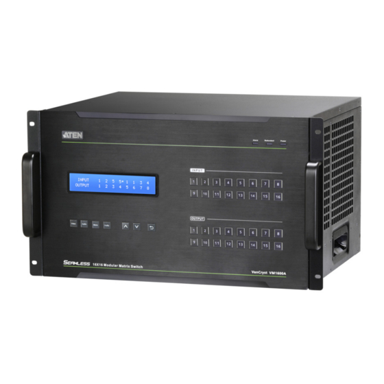
- Page 1 16 x 16 Modular Matrix Switch VM1600A User Manual www.aten.com...
-
Page 2: Emc Information
© Copyright 2021 ATEN® International Co., Ltd. Released: 2021-02-08 ATEN and the ATEN logo are registered trademarks of ATEN International Co., Ltd. All rights reserved. All other brand names and trademarks are the registered property of their respective owners. The terms HDMI, HDMI High-Definition Multimedia Interface, and the HDMI Logo are trademarks or registered trademarks of HDMI Licensing Administrator, Inc. -
Page 3: Table Of Contents
VM1600A ........ - Page 4 VM1600A Front View ........
- Page 5 Modular Matrix Solution User Manual Operation Mode ..........57 EDID .
- Page 6 Modular Matrix Solution User Manual Power Status ........105 Serial Settings .
- Page 7 VM1600A ........
-
Page 8: About This Manual
Modular Matrix Solution User Manual About this Manual This User Manual is provided to help you get the most from your VM1600A Modular Matrix Solution system, which includes the following the following product models: Device Type Model Product Name Modular Matrix Switch VM1600A... -
Page 9: Conventions
For information about all ATEN products and how they can help you connect without limits, visit ATEN on the Web or contact an ATEN Authorized Reseller. Visit ATEN on the Web for a list of locations and telephone numbers: International http://www.aten.com... -
Page 10: User Information
Japan 81-3-5615-5811 Korea 82-2-467-6789 North America 1-888-999-ATEN ext 4988 1-949-428-1111 User Notice All information, documentation, and specifications contained in this manual are subject to change without prior notification by the manufacturer. The manufacturer makes no representations or warranties, either expressed or implied, with respect to the contents hereof and specifically disclaims any warranties as to merchantability or fitness for any particular purpose. -
Page 11: Package Contents
Check to make sure that all components are present and that nothing was damaged in shipping. If you encounter a problem, contact your dealer. VM1600A The VM1600A package consists of: 1 VM1600A Modular Matrix Switch 1 Power Module 1 Power Cord 1 Terminal Block connector ... -
Page 12: Vm7514 / Vm8514
Modular Matrix Solution User Manual VM7514 / VM8514 The 4-Port HDBaseT Input / Output Board package consists of: 1 VM7514 4-Port HDBaseT Input Board / 1 VM8514 4-Port HDBaseT Output Board 4 Terminal Blocks 1 IR Transmitter ... -
Page 13: Vm7804 / Vm8804
Modular Matrix Solution User Manual VM7804 / VM8804 The 4-Port HDMI Input / Output Board package consists of: 1 VM7804 4-Port HDMI Input Board / 1 VM8804 4-Port HDMI Output Board 4 Terminal Blocks 1 User Instructions VM7604 / VM8604 The 4-Port DVI Input / Output Board package consists of: ... -
Page 14: Ve805R
Modular Matrix Solution User Manual VE805R The HDMI HDBaseT Lite Receiver with Scaler package consists of: 1 VE805R HDMI HDBaseT Lite Receiver with Scaler 1 Power Adapter 1 Terminal Block 1 IR Transmitter 1 IR Receiver ... -
Page 15: Introduction
VM1600A to route 4 HDMI sources over long distances via optical extenders, the VE883 to 4 HDMI-enabled displays. These I/O boards are able to route uncompressed 4K signal to the VM1600A from up to 300 m (VM7584K1 and VM8584K1) or 10 km (VM7584K2 and VM8584K2) away over duplex fiber optic cables. - Page 16 Modular Matrix Solution User Manual The VM7814 / VM8814 is a 4-Port 4K HDMI input/output board that works with VM1600A to route 4 HDMI sources to 4 displays. The VM7814 / VM8814 is equipped with 4 input/output ports to allow for stereo audio embedding and audio extraction.
- Page 17 Setup is fast and easy; install the modular I/O boards by sliding them into the VM1600A’s rear panel slots, then plug the device cables into the appropriate ports on the I/O boards and your ready. This solution can be connected to the network through the VM1600A’s LAN port, allowing the installation to take advantage of internal Cat 5 Ethernet wiring built into most modern commercial buildings.
-
Page 18: Features
Modular Matrix Solution User Manual Features VM1600A 16 x 16 I/O connections via 4 x4 I/O slots for modular matrix boards Multiple control methods – system management via front-panel pushbuttons, RS-232/RS-422/RS-485, and Ethernet connections for web GUI or Telnet ... - Page 19 Chapter 1. Introduction Note: Features marked with an asterisk (*) are supported only with specific I/O boards. For more information, see the feature descriptions for I/O boards in this manual. The maximal output resolution, and the Scaler, Seamless Switch™ and video wall features are only supported with certain I/O boards.
-
Page 20: Vm7584 / Vm8584
Modular Matrix Solution User Manual VM7584 / VM8584 Compatible with the VM1600A; mix and match with modular output boards of any type for optimum flexibility Extends audio, video, IR, and RS-232 control signals over long distances via duplex fiber optic cables ... -
Page 21: Vm7514 / Vm8514
Chapter 1. Introduction VM7514 / VM8514 Compatible with the VM1600A; mix and match with modular I/O boards of any type for optimum flexibility Superior video quality up to 4K when used with VE816R Long-distance transmission up to 100 m ... -
Page 22: Vm7904
Compatible with the VM1600A; mix and match with modular I/O boards of any type for optimum flexibility Connects up to 4 DisplayPort inputs to up to 16 (VM1600A) displays Superior video quality – up to 4096 x 2160 / 3840 x 2160 @ 30 Hz (4:4:4) ... -
Page 23: Vm7824 / Vm8824
Chapter 1. Introduction VM7824 / VM8824 Partially compatible with the VM1600A*; mix and match with modular I/O boards of any type for optimum flexibility Superior video quality – HDTV resolutions of 480p, 720p, 1080i, and 1080p (1920 x 1080); 4K2K @ 60Hz (4:2:0) ... -
Page 24: Vm7814 / Vm8814
Modular Matrix Solution User Manual VM7814 / VM8814 Compatible with the VM1600A; mix and match with modular I/O boards of any type for optimum flexibility Superior video quality – HDTV resolutions of 480p, 720p, 1080i, and 1080p (1920 x 1080); 4K2K @ 60Hz (4:2:0) ... -
Page 25: Vm7804 / Vm8804
Chapter 1. Introduction VM7804 / VM8804 Compatible with the VM1600A; mix and match with modular I/O boards of any type for optimum flexibility Superior video quality – HDTV resolutions of 480p, 720p, 1080i (1920 x 1080), and 1080p (1920 x 1080) ... -
Page 26: Vm7604 / Vm8604
Modular Matrix Solution User Manual VM7604 / VM8604 Compatible with the VM1600A; mix and match with modular I/O boards of any type for optimum flexibility Scaler – features a video scaling function to convert input resolutions to the optimum display resolutions* (VM8604 only) ... -
Page 27: Vm7104
Chapter 1. Introduction VM7104 Compatible with the VM1600A; mix and match with modular I/O boards of any type for optimum flexibility Connects up to 4 VGA or Component inputs Supports RGBHV / RGBS / YPbPr / YCbCr input signals ... -
Page 28: Ve805R
Note: The Seamless Switch™ and the video wall functions are only available when the VE805R is used with the ATEN HDBaseT I/O boards. When Seamless Switch™ or Video Wall is enabled, videos may not display within range, in which case make sure to adjust the display settings on your device. -
Page 29: Ve816R
Note: The Seamless Switch™ and the video wall functions are only available when the VE816R is used with ATEN HDBaseT I/O boards. When Seamless Switch™ or Video Wall is enabled, videos may not display within range, in which case make sure to adjust the display settings on your device. -
Page 30: Requirements
Modular Matrix Solution User Manual Requirements The following are required for a complete VM1600A Modular Matrix Solution Series installation: Input / Output Board VM7584 (4-Port 10G Optic Input Board) and VM8584 (4-Port 10G Optic Output Board) VM7514 (HDBaseT input board) and VM8514 (HDBaseT output board) ... -
Page 31: Display Devices
Chapter 1. Introduction For VM7804 4-port HDMI input board: Digital AV source device with HDMI output connector(s) For VM7604 4-Port DVI input board: Digital AV source device with DVI output connector(s) For VM7104 4-Port VGA input board: AV source device with VGA output connector(s) ... - Page 32 1 audio cable for each audio device / speaker (VM8824 /VM8814 / VM8804 / VM8604) 1 Ethernet cable (VM1600A) 1 RS-232 serial cable (VM1600A / VM7514 / VM8514 / VE805R / VE816R) 1 RS-485/RS-422 serial cable (VM1600A) ...
-
Page 33: Compatible Browsers
Windows 10 x64 V1.8.0_181 (64 bit) Baidu 10.2.1 9.1.0.434 Optional Equipment Purchase optional equipment such as a secondary power module, fan, or rack mount kit to get the most out of your ATEN Modular Matrix. For more information go to https://www.aten.com/global/en/... -
Page 34: Components
Panel Pushbuttons, page 43, for details. Note: The pushbuttons have LEDs that light to indicate they have been selected. Input These pushbuttons refer to the Input ports on the VM1600A Pushbuttons rear panel. Press to select the Input port. These pushbuttons (1-16) may also correspond to menu options, profiles and other selections. - Page 35 Chapter 1. Introduction Component Description Redundant This LED lights green to indicate the redundant power module Power LED is plugged in and working. Primary Power This LED lights green to indicate the primary power module is plugged in and working. Handles The two front handles are used to install the unit into a rack.
-
Page 36: Vm1600A Rear View
Connect a computer or high-end system controller via this serial port. Ethernet Port In order to access the VM1600A’s web Graphical User Interface (GUI), the VM1600A must be connected to the network. The cable that connects the VM1600A to your LAN plugs in here. For further details, see Installation, page 38. -
Page 37: Power Module
Receives a power cord which connects to a power source at the other end. Power Module Press this lever to unlock the power module and remove it Release Lever from the VM1600A device. Cable Strap Optionally use this strap to hold the power cable in place. - Page 38 Modular Matrix Solution User Manual Component Description Power Module Use the handle with the Release Lever to remove the power Handle module from the VM1600A device.
-
Page 39: Vm7584 Front View
Chapter 1. Introduction VM7584 Front View Component Description Link LEDs Light up to indicate stable connection with the connected source devices. SFP+ Ports Connect up to four VE883T units via SFP+ modules to receive data from input devices. IR Ports Connect to the supplied IR Receiver or IR Emitter to bypass IR signals via the VM7584. -
Page 40: Vm8584 Front View
Modular Matrix Solution User Manual VM8584 Front View Component Description Link LEDs Light up to indicate stable connection with the connected source devices. SFP+ Ports Connect up to four VE883R units via SFP+ modules to transmit data to output devices. IR Ports Connect to the supplied IR Receiver or IR Emitter to bypass IR signals via the VM8584. -
Page 41: Vm7514 Front View
Chapter 1. Introduction VM7514 Front View Component Description HDBaseT Input Ports Connect the Cat 5e cables from your HDBaseT transmitter to these ports. IR / RS-232 Connect the cables from your IR transmitter to the mini stereo jack ports, and connect the cables from your Input Ports RS-232 device to the RS-232 ports. -
Page 42: Vm7904 Front View
Link LEDs Lights up to indicate stable connection with the connected source devices. ATEN LockPro™ Optionally secure an ATEN LockPro™ to hold a the Screws HDMI cable in place and prevent it from falling off. Status LED Indicates the working status of the unit. -
Page 43: Vm8824 Front View
Link LEDs Lights up to indicate stable connection with the connected display devices. ATEN LockPro™ Optionally secure an ATEN LockPro™ to hold a the Screws HDMI cable in place and prevent it from falling off. Status LED Indicates the working status of the unit. -
Page 44: Vm8814 / Vm8804 Front View
Modular Matrix Solution User Manual VM8814 / VM8804 Front View Component Description HDMI Output Ports Connect the cables from your HDMI display devices (monitors, projectors, TVs) to these ports. Audio Output Ports Connect the cables from your output audio devices or speakers to these ports. -
Page 45: Vm8604 Front View
Chapter 1. Introduction VM8604 Front View Component Description DVI Output Ports Connect the cables from display devices (monitors, projectors, TVs) to these ports. Audio Output Ports Connect the cables from your output audio devices or speakers to these ports. Status LED The VM8604 has an LED to indicate the working status. -
Page 46: Vm7404 Front View
Modular Matrix Solution User Manual VM7404 Front View Component Description SDI Input Ports Connect the cables from your video source devices to these ports. Analog Stereo Audio Connect the cables from your audio source devices to these ports. Input Ports Status LED The VM7404 has an LED to indicate the working status. -
Page 47: Ve805R / Ve816R Front View
Chapter 1. Introduction VE805R / VE816R Front View VE805R / VE816R Rear View Component Description LEDs Three LEDs – Power, Link and HDMI Out – light when the unit is properly connected to an appropriate source. Power - lights Green to indicate the unit is receiving power. - Page 48 Modular Matrix Solution User Manual This Page Intentionally Left Blank...
-
Page 49: Hardware Setup
Its important to properly transport and store the VM1600A. Follow the instructions below to avoid damaging the VM1600A due to improper handling. When not rack mounted, the VM1600A should be placed on a flat and level surface with the bottom side down. The unit should never be placed with the front, rear or sides facing the ground. -
Page 50: Rack Mounting
Modular Matrix Solution User Manual Rack Mounting The Modular Matrix Swtich can be mounted in a 19” (1U) system rack. For the most convenient front panel operation at the local site, mount the unit at the front of the rack, as follows: 1. -
Page 51: Mounting With Brackets
Chapter 2. Hardware Setup Mounting with Brackets You can also use mounting brackets to install the VM1600A, as shown below. Note: The Mounting Kit is not included with the package. To purchase a mounting kit please contact your dealer. 1. Screw the mounting brackets (Easy Installation Rack Mount Kit, see page 19) to the rack, as shown in the diagram. -
Page 52: Installation
Note: Do not omit this step. Proper grounding helps to prevent damage to the unit from surges or static electricity. 2. Unscrew the covers on the VM1600A rear panel and insert the I/O boards into the horizontal slots (See Input / Output Board Installation, page 40, for details). - Page 53 Matrix Control App User Manual. 7. (Optional) If you are using a serial control function, use an appropriate serial cable to connect the computer or serial controller to the VM1600A’s female RS-232 serial port. 8. (Optional) If you are using the serial control function to control multiple VM1600A’s, use an appropriate serial cable to connect the computer or...
-
Page 54: Input / Output Board Installation
Note: The four top slots on the Modular Matrix Switch are for the Input boards. The four bottom slots on the Modular Matrix Switch are for the Output boards. 1. On the rear of the VM1600A, unscrew the two screws from a top and bottom slot, and remove the covers. - Page 55 VM1600A. 3. Slide an output board into a bottom slot and tighten the screws to secure the board to the VM1600A. 4. Repeat steps 2 and 3 to install additional I/O boards. 5. Power on the VM1600A.
- Page 56 Modular Matrix Solution User Manual This Page Intentionally Left Blank...
-
Page 57: Front Panel Operation
The VM1600A front panel has easy-to-use pushbuttons for selecting which video/audio source shows on which display. Basic Navigation The VM1600A’s front panel LCD display operation is easy and convenient. Please note the following front panel button operations: Press the VIDEO pushbutton to configure the video connections. -
Page 58: Front Panel Lcd
If the VM1600A has been configured to require a password for local operation (see Security Mode, page 63), the password screen appears when the VM1600A is powered on, and the cursor flashes on the first digit. Enter a 4- digit password to continue to the Main Screen. -
Page 59: Port Switching
Chapter 3. Front Panel Operation Port Switching From the Main Screen, you can configure the Input-to-Output port connections to associate an Input source device to an Output display. Video / Audio Pushbutton Before switching port connections, use the Video or Audio pushbuttons to select whether to switch only the video or the audio signal exclusively. -
Page 60: Input Port Selection
Modular Matrix Solution User Manual Input Port Selection Use the Input Port pushbuttons to select the Input port you want to configure. INPUT OUTPUT INPUT V + A OUTPUT 9 10 11 12 13 14 15 16 To select which input source displays on each output port, do the following: 1. - Page 61 Chapter 3. Front Panel Operation 4. To connect Output port 2 to Input port 2 in the example above, press the Output port 2 pushbutton. The Output port 2 LED will also light up. This indicates that Input port 2 is now connected to Output ports 2, 3 and 4. Once the signal from the selected Input port is successfully tied to the Output port, the LEDs turn off and the LCD information is updated.
-
Page 62: Output Port Selection
Modular Matrix Solution User Manual Output Port Selection Use the Output Port pushbuttons to select the Output port you want to configure. INPUT OUTPUT INPUT V + A OUTPUT 9 10 11 12 13 14 15 16 To select which output display corresponds to each input source, do the following: 1. - Page 63 Chapter 3. Front Panel Operation 4. To switch Output ports 2, 3 and 4 to another Input port (and disconnect it from Input port 2), press another Input port pushbutton to which you want them tied. In the example below, Input port 3 has been pressed and is now connected to Output ports 2, 3 and 4.
-
Page 64: Profile Pushbutton
Note: If a Profile is available for selection, its corresponding Input/Output port LED lights. The selected pushbutton lights steady, and the VM1600A immediately applies the port connections configured in the Profile. The selected Profile is shown as P1-P32 in the LCD’s lower right corner. -
Page 65: Lcd Menu
Break Output Group Note: Default settings are indicated in bold. Upon VM1600A startup, check the front panel LCD to view the loading progress. If the LCD Menu fails to load, an error message displays. Reset the unit and try again. -
Page 66: Lcd Main Screen
Modular Matrix Solution User Manual LCD Main Screen The Main Screen shows the Input–Output port pairs, with the Output ports shown in sequential order (1–16) at the bottom half. INPUT OUTPUT INPUT V + A OUTPUT 9 10 11 12 13 14 15 16 ... -
Page 67: Ip Setting
Chapter 3. Front Panel Operation IP Setting To view the VM1600A’s IP settings, press the Menu pushbutton (lights). This takes you to the Menu page, shown below: 1: IP Se ng 2: Serial Port Se ng 3: Opera on Mode 4: Security Mode 1. -
Page 68: Serial Port Setting
Modular Matrix Solution User Manual Serial Port Setting To configure the VM1600A’s serial port settings, select Serial Port Setting from the Menu page. 1: IP Se ng 2: Serial Port Se ng 3: Opera on Mode 4: Security Mode Serial Port Address Setting To set the VM1600A’s serial port address, do the following:... -
Page 69: Baud Rate
Chapter 3. Front Panel Operation Baud Rate 1. Select Baud Rate Setting from the Serial Port Setting submenu by pressing 2: 1: Serial Port Address Se ng : 1 2: Baud Rate Se ng: 19200 3: Serial Port Mode: RS232 2. - Page 70 Modular Matrix Solution User Manual 2. Press pushbuttons 1–2 to make your selection. 1: RS232 (In use) 2: RS422/RS485 Serial Port options are: 1: RS-232 2: RS-422 / RS-485 Note: The default serial port mode is RS-232. 3. Press Menu to return to the Menu page. 4.
-
Page 71: Operation Mode
Chapter 3. Front Panel Operation Operation Mode The EDID, CEC, OSD and Output Status features are adjusted from the Operation Mode menu. 1: EDID Mode: Default 2: CEC 3: OSD 4: Output Status EDID (extended display identification data) is used to apply a preset video configuration (EDID Mode), which utilizes the best resolution across different monitors. - Page 72 EDID Mode options are: EDID Option Description 1: Default ATEN’s default EDID data is passed to all video sources by default when the system is powered on. 2: Port1 EDID data read from port 1 is passed to all video sources.
-
Page 73: Cec
Chapter 3. Front Panel Operation To configure the CEC settings, do the following: 1. From the Operation page, press pushbutton 2 to access the CEC page: 1: EDID Mode: Default 2: CEC 3: OSD 4: Output Status 2. Press pushbuttons 1–16 to enable (ON) or disable (NA) the CEC feature for the output port. -
Page 74: Osd
The On-Screen Display or OSD feature enables real-time text updates to appear on the display device’s screen for any configuration changes made to the Output port via the VM1600A’s front panel, remote control or Web GUI. To configure the OSD setting for each output port, do the following: 1. -
Page 75: Output Status
Chapter 3. Front Panel Operation Output Status To configure the Output Status settings for each output port, do the following: 1. From the Operation Mode screen, press pushbutton 4 to access the Output Status page: 1: EDID Mode: Default 2: CEC 3: OSD 4: Output Status 2. - Page 76 Modular Matrix Solution User Manual 5. If configuring the output video resolution, press pushbuttons 1–16 to select the output port. Next, select the preferred output resolution. 6. Press Menu to return to the Menu page. 7. Press Cancel to return to the previous step without saving.
-
Page 77: Security Mode
Security Mode page. 1: Mode 2: Change Password Mode 1. To set the VM1600A so that it requires a password for local operation, press pushbutton 1 in the Security Mode page. 1: Mode 2: Change Password 2. To disable security settings, press pushbutton 1. -
Page 78: Change Password
Modular Matrix Solution User Manual 5. Press Menu to return to the Menu page. 6. Press Cancel to return to the previous step without saving. Change Password 1. To change the password: from Security Mode, press pushbutton 2. 1: Mode 2: Change Password 2. - Page 79 Chapter 3. Front Panel Operation 4. Re-enter the new password in the following screen. The new password is applied by the VM1600A immediately. Old Password : * * * * New Password: * * * * Re-enter New Password: * * * * If the password you entered does not match the one entered in the previous screen, an error message appears.
-
Page 80: Playing/Stopping The Profile Schedule
Profiles, page 72 and Profile Scheduling, page 94. Enabling/Disabling the Standby Mode The standby mode is a low-power mode where the VM1600A operates minimally by stopping all input and output transmissions and logging the user out of the web GUI. -
Page 81: Break Output Group
Chapter 3. Front Panel Operation Break Output Group You can disintegrate a grouped display (video wall) into individual displays. For example, if you have three 2 x 2 display zones (video walls) set up, and each is playing a profile, you can enable this function to have the assigned source displayed separated on each of the 4 monitors. - Page 82 Modular Matrix Solution User Manual This Page Intentionally Left Blank...
-
Page 83: Browser Operation
Logging In To access the GUI, type the VM1600A’s IP address into the address bar of any browser. If a Security Alert dialog box appears, accept the certificate – it can be trusted. The login screen appears: ... -
Page 84: Main Page
Modular Matrix Solution User Manual Main Page The main page opens to Profile List. Use the Profile List page to configure profiles which define the input to output connections. The page is divided into three parts – the Menu Bar (page 71), Profile List (page 72), and Profile Scheduling (page 94). -
Page 85: Menu Bar
For details, see Profiles, page 72. Standby Click to set the VM1600A to standby mode. For details, see Setting the Standby Mode, page 71. Logout Click to log out of the VM1600A web GUI. -
Page 86: Profiles
– for example, a 2 x 2 video wall, a 4 x 4 video wall, and a single-monitor display, all managed by one VM1600A. In this case, you have three display zones. To be able to switch profiles independently on just one display zone, instead of on all the display zones, use the zone tabs to help you organize and create profiles. -
Page 87: Example
Chapter 4. Browser Operation Example In the illustrated Profile List below, the profiles are created for three display zones (A, B, and C). Three profiles (profile 1 to 3) are created for zone A, and profile 4 to 6, created under zone B and C are not configurable under zone A. -
Page 88: Creating A Profile
Modular Matrix Solution User Manual Creating a Profile 1. Prepare and gather the following information. Know which display zone the profile is created for. For information on the working of profiles on multiple display zones, see Understanding Display Zones, page 72. ... - Page 89 Chapter 4. Browser Operation 5. Follow the on-screen instructions to select a template and define the number of displays for the display zone. New: Select this option to configure a profile from scratch. Copy: Select this option to configure a profile based on an existing profile.
- Page 90 Modular Matrix Solution User Manual 7. Click Save to finish the configuration. The profile immediately appears in the Profile List.
-
Page 91: Configuring Video Settings Of A Profile
Chapter 4. Browser Operation Configuring Video Settings of a Profile 1. In the Profile List, locate the profile you wish to configure by clicking the zone tab. 2. Click the profile and then click Edit. This screen appears. 3. You can choose either the Normal View or the Grid View to edit the profile. - Page 92 Modular Matrix Solution User Manual Grid View In grid view, the audio and video outputs are assigned by mapping the audio/video input on the vertical axis to the audio/video output on a horizontal axis. For detailed information, see Configuring Video Settings in Grid View, page 86.
-
Page 93: Configuring Video Settings In Normal View
Chapter 4. Browser Operation Configuring Video Settings in Normal View Profile Layout Settings Control Description Number of Use the following controls to configure the layout type and the number Displays of displays. Video Wall: Select this option for displays that are tiled together, where multiple monitors form one large screen –... -
Page 94: Display Preferences
Modular Matrix Solution User Manual Display Preferences To configure the display preferences for one or more displays, click the display(s) in the preview, the Display Preference settings page appears. Configure the settings as required. Option Description Output This indicates the selected displays. Video Input Click to select a video source for the output(s). -
Page 95: Video Wall Settings
Chapter 4. Browser Operation Video Wall Settings Each icon represents an Output port and the connected display. Use the icons to create Independent and Grouped Outputs. Independent Outputs will display video on a single monitor. Grouped Outputs will display video across multiple monitors as one large screen. - Page 96 Modular Matrix Solution User Manual Null Input Option Description Null Icon Click Null Input icons to highlight icons in green and use the Display Preferences menu to set the video options (see Video Wall Example 1, page 84). Select a single icon to set the Output and Video Input for an independent display (see , page 82).
- Page 97 Chapter 4. Browser Operation Grouping Option Description Grouping Click multiple icons to Group Outputs (highlighted in green) and →|← click to group the displays into one screen. Use the Display Preferences menu to select the Video Input for the group - each Output icon in the Group will appear with the same Video Input number and icon color (see page 83).
- Page 98 Modular Matrix Solution User Manual Video Wall Example 1 The example below shows a video wall with 8 displays. Each Group and Independent Output has a unique color. This video wall has 1 Group and 4 Independent displays. ...
- Page 99 Chapter 4. Browser Operation Video Wall Example 2 The example below shows a video wall with 16 displays. Each Group and Independent Output has a unique color. This video wall has 3 Groups and 2 Independent displays. The Blue Group will show Video Input 02 across six displays as one large screen.
-
Page 100: Configuring Video Settings In Grid View
Modular Matrix Solution User Manual Configuring Video Settings in Grid View In a grid view, the audio and video outputs are assigned by mapping the audio/ video input on the vertical axis to the audio/video output on a horizontal axis. 1. - Page 101 Chapter 4. Browser Operation Example 2 To assign the same input for all outputs, click the input from the vertical axis. In the following illustration, all output ports are assigned with input Example 3 To have an audio output automatically switch to the audio input that comes along with the assigned video input, click AFV (audio following video).
-
Page 102: Configuring Audio Output Settings
Modular Matrix Solution User Manual Configuring Audio Output Settings 1. In the Profile List, locate the profile you wish to configure by clicking the zone tab. 2. Click the profile and then click Edit. This screen appears. 3. Click from the top-right corner to switch to the audio settings page. ... - Page 103 Chapter 4. Browser Operation Port: Use this field to apply the same audio setting to all digital audio output ports. All ports follow video path: Sets all digital audio outputs to receive the digital audio inputs that come with their video inputs as these videos display.
-
Page 104: Playing A Profile
Modular Matrix Solution User Manual Playing a Profile Apply Multiple Profiles by Batch 1. In the Profile List page, click the Apply by Batch button (top-right corner). This dialog box appears. 2. Use the drop-down menus to select the profile for each display zone and click Apply. -
Page 105: Apply A Single Profile
Chapter 4. Browser Operation Apply A Single Profile 1. In the Profile List, locate the profile you wish to play by clicking the zone tab. 2. Click the profile and then click Apply. 3. The profile is immediately applied and appears in the large Play window. - Page 106 Modular Matrix Solution User Manual 4. To adjust the played profile, click on the Play window. The following controls appear. Option Description Show OSD Check Show OSD to show the current connection status via OSD. When Show OSD is unchecked, the OSD will disappear. Mute All Check Mute All to mute the audio for all ports.
-
Page 107: Importing/Exporting A Profile
Chapter 4. Browser Operation Importing/Exporting a Profile To export the VM1600A’s connection profiles, click Export Profiles. A configuration file starts downloading. To import connection profiles to the VM1600A, do the following: 1. Click Import Profiles. 2. Browse to the configuration file, select it and click Open. -
Page 108: Profile Scheduling
Note: For firmware prior to version 4.2.416, if profile scheduling is disabled and re-enabled within the scheduled time frame of a playlist, the VM1600A will resume playing the first profile in the playlist; for VM1600A of firmware version 4.2.416 or later, the system will resume playing the playlist according to schedule, and the profiles that were to be played during the paused period will be skipped. -
Page 109: Adding Profile Playlists
Chapter 4. Browser Operation Adding Profile Playlists Adding a Recurring Playlist To add a playlist that plays periodically, follow the steps below. 1. From the Profile List page, click PROFILE SCHEDULING. The profile calendar appears. 2. Click the display zone tab to select a display zone to which you wish to add a playlist. - Page 110 Modular Matrix Solution User Manual 4. Configure the playlist. a) Configure the Name, Start Time, End time, and Frequency. b) Click to open the Select Profiles window. Click one or more profiles to add to the playlist.
- Page 111 Chapter 4. Browser Operation c) Click OK. The selected profiles are added to the playlist. The profiles will be played from left to right. Adjust the play duration and the order of the added profiles if required. See the table below for more details. Option Description Use the drop-down menu to select Hour(s), Minutes, or...
-
Page 112: Adding A One-Off Profile Playlist
Modular Matrix Solution User Manual Adding a One-off Profile Playlist To add a playlist that plays once, follow the steps below. 1. From the Profile List page, click PROFILE SCHEDULING. The profile calendar appears. 2. Click the display zone tab to select a display zone to which you wish to add a playlist. - Page 113 Chapter 4. Browser Operation 4. Click Profile List at the bottom of the page. The Profile List appears. 5. From the Profile List, drag and drop profiles onto the desired time on the calendar view. Optionally right-click the profile to copy, remove, or view its settings.
-
Page 114: Editing, Removing, Or Copying Profile Playlists
Modular Matrix Solution User Manual Editing, Removing, or Copying Profile Playlists To edit, remove, or copy profile playlists: 1. Locate the playlist by clicking the zone tab. 2. Click the button from the Profile List page to open the All Playlist window. -
Page 115: System Settings
Chapter 4. Browser Operation System Settings Overview The setting pages allow you to configure the VM1600A’s system settings. If your Web GUI is not showing these setting, click the Settings icon from the top-right corner in the web interface. - Page 116 Status For more information, View statuses of the input/output boards see YCBCR 4:2:0 Video installed to the VM1600A and enable/ Data Block, page 122. disable FrameSynce and Long Reach mode for the board. View system information such as...
- Page 117 Supported Functions Detailed Information Maintenance See Maintenance, Upgrade the firmware for the installed page 128. input and output boards Back up or restore the VM1600A’s configuration Add, edit, or remove user accounts Configure the system network settings...
-
Page 118: General
Modular Matrix Solution User Manual General Basics Device Name: Type to name your Modular Matrix Switch. Language: Click to select a language for the web interface. System Time Click Edit to configure the system date and time settings. Fan Status ... -
Page 119: Power Status
VM1600A’s system via RS-232 serial commands. RS-232 Control Mode: Allows the user to control remote devices that are connected to VM1600A through its RS-232 channels. To enable this feature, select the RS232 Control Mode and configure the input to output settings. -
Page 120: Port Settings
Modular Matrix Solution User Manual Port Settings OSD/CEC The OSD/CEC page lets users view and set OSD and CEC settings for all ports. OSD: Sets the default OSD option for the port. When OSD is on, real- time text updates appear on the display for 10 seconds when configuration and port changes are made to its output. -
Page 121: Hdcp
Chapter 4. Browser Operation HDCP The HDCP page lets users view and set HDCP key settings between input and output ports for digital copy protection and to ensure Seamless Switch™ is used between different devices. This is an Administrator and Advanced User only function. -
Page 122: Scaler
Modular Matrix Solution User Manual Scaler The Video settings page allows you to set Seamless Switch™ options which determine how a display performs when the Input port is changed. Note: Seamless Switch™ is enabled: When The Transition, Period and Scale Resolution options can be enabled. ... - Page 123 Chapter 4. Browser Operation Period: Sets the fade speed for the Transition option. Use the drop-down menu to apply an option (Slow, Normal, or Fast) to all ports, or lower drop-down menus to apply options per port. Scale Resolution: Forces the port to scale the video displayed to the selected resolution.
-
Page 124: Port Name
Modular Matrix Solution User Manual Port Name The Annotation page lets users name the Input and Output ports for easy identification. To name an Input/Output port, enter a descriptive name of up to 16 characters (including 0-9, a-z, A-Z, _, -) in the corresponding field. ... -
Page 125: Edid Settings
EDID Settings The EDID Setting page lets users view and select an EDID Mode so that the VM1600A can use the best resolution for its displays. Note: The EDID Mode can also be selected via the Front Panel pushbuttons –... -
Page 126: Edid Mode
In the left panel of the page, users can select a pre-configured EDID Mode using the EDID Mode radio buttons. Select the EDID Mode to use and click Apply. The VM1600A uses the settings configured for that EDID mode. Options are: ... -
Page 127: Edid & Cea Description
Chapter 4. Browser Operation EDID & CEA Description The middle panel of the screen lets users view and configure the EDID or the CEA mode. From the middle column, click the option that you want to view and/or edit. There are two categories: EDID (Extended Display Identification Data) and CEA (Consumer Electronics Association). -
Page 128: Customized Mode
Modular Matrix Solution User Manual Customized Mode Use the Customized mode to automatically retrieve and save the EDID of a connected monitor/display device to an input source port. In the left panel, select Customized from the EDID Mode section and click Apply. -
Page 129: Customized Edid Parameters
Chapter 4. Browser Operation Customized EDID Parameters The EDID structure is comprised of 128 bytes in total – each heading shown in the left column corresponds to a specific number of bytes. The pages for the pre-configured EDID Modes (Port 1, Default and Remix) cannot be edited. - Page 130 Modular Matrix Solution User Manual Standard Timings This page shows eight resolutions/timings that display devices can support in addition to those listed in the Established Timings page. Select the H Active Pixel from the drop-down menu. Select the Aspect Ratio from the drop-down menu. ...
- Page 131 Chapter 4. Browser Operation Monitor Description This screen lets you specify the viewing specifications, namely horizontal and vertical scan ranges and pixel clock rate, of your monitor/display device. Enter the values that correspond to your device and click Save to apply the changes.
-
Page 132: Cea Settings
Modular Matrix Solution User Manual CEA Settings CEA is an extension data of the EDID structure, which further extends the standard definitions of EDID to support advanced features of monitors/display devices. Display Support This screen describes the display’s basic digital components. Select the YCbCr mode applicable to your display and click Save. -
Page 133: Video Data
Chapter 4. Browser Operation Video Data This screen lists additional video resolution/timing displays that may be supported by other devices, other than PC monitors (for example, 1080i). Select the native resolution of the attached display device. Select the resolutions that work with the attached monitor/display device. ... -
Page 134: Audio Data
Modular Matrix Solution User Manual Audio Data This screen lets you select advanced audio configurations for your device. Use the drop down menu to select the Audio Format (1~6) applicable to your audio output device, and click Save to apply the changes. -
Page 135: Hdmi Forum Vendor Specific Block
Chapter 4. Browser Operation HDMI Forum Vendor Specific Block This screen shows the display device’s supported video parameters. Use the toggle button to enable or disable this function. 3D OSD Disparity: Select this option to have Sink support receiving 3D OSD Disparity Indication in the HF-VSIF. -
Page 136: Ycbcr 4:2:0 Video Data Block
Modular Matrix Solution User Manual YCBCR 4:2:0 Video Data Block Use this page to configure a list of supported YCBCR 4:2:0 video resolutions and select one to be applied. Use the toggle button at the top-right to enable or disable this feature. ... -
Page 137: Ycbcr 4:2:0 Compatibility Map Data Block
Chapter 4. Browser Operation YCBCR 4:2:0 Compatibility Map Data Block Use this page to configure a list of supported video resolutions for YCBCR 4:2:0 Compatibility Map Data Block and select one to be applied. Use the toggle button at the top-right to enable or disable this feature. ... -
Page 138: Status
Connections The connections tab provides a status summary of the input/output boards installed to the VM1600A and the devices that are connected to the ports on the input/output boards. If the connected devices support FrameSync and Long Reach mode, you can also enable/disable the function on this page. -
Page 139: System Information
Chapter 4. Browser Operation System Information Use this page to look up system settings, including system network settings, firmware version, video/audio input assignments, output audio volumes, CED/ OSD settings, output resolutions, HDMI audio mode settings, and power statuses. Hint: Click to view details and to refresh the system. -
Page 140: Channel
Modular Matrix Solution User Manual Channel IR/RS-232 The IR/RS-232 page is used to configure the IR/RS-232 communication routes between the input and output ports. Note: The IR/RS-232 pages are only supported by VM7514/VM7584 and VM8514/VM8584 boards. In-Board: Use this set of settings to configure the IR/RS-232 signals for each input port. -
Page 141: Ir/Rs-232
Chapter 4. Browser Operation Use Loopback for the IR/RS-232 signals to be sent back to local source or local display device connected to the same port on the same I/O board. This allows you to use the IR/RS-232 connection to control devices locally. -
Page 142: Maintenance
To upgrade the VM1600A’s firmware, do the following: 1. Download the firmware package from ATEN’s official website. 2. In the VM1600A web interface, go to Maintenance > System Setup > Firmware Upgrade > Mainboard I/O Board, click Browse to locate the firmware upgrade package. - Page 143 PC. 2. Click Restore to begin the restoration procedure. Note: User accounts cannot be backed up or restored. To reset the VM1600A to its default settings, click the reset to default button on the far right.
-
Page 144: User Account
Note: This is an Administrator only function. Add account – Click the Add account button to add another user to the list. The VM1600A supports up to 32 users and up to 16 concurrent logins (see page 130 for more details). -
Page 145: Add Account
Click Create User to save the data. Click Cancel to discard the changes and exit. If a user is logged into the VM1600A’s GUI, their user settings cannot be edited, and the fields in this screen are grayed out. -
Page 146: Permission Level
The three available permission levels are as follows: Administrator – this level provides full access and control of the VM1600A, in addition to full User Management privileges. Advanced User – this level provides full access and control with no User Management privileges. -
Page 147: Network
GUI, and enable/disable Telnet. Enable DHCP to allow the DHCP server to assign an IP address to the VM1600A. Select Disable to enter your own static IP address settings for the device. Click Reset to use the following default values: ... - Page 148 Modular Matrix Solution User Manual This Page Intentionally Left Blank...
-
Page 149: Cli Commands
5. At the login prompt, type the login username and password for the VM1600A. 6. When a session is established with the VM1600A, you can control and configure the VM1600A via RS-232 commands. For more information on commands, see Commands, page 138 Note: If a user logs in using a username that is already in session, the newest login takes effect and the previous session will be replaced. -
Page 150: Connecting To The Matrix Switch Via Rs-232
2) Microsoft 64-bit ODBC and OLEDB driver. To connect to the VM1600A via RS-232, do the following: 1. Connect the RS-232 serial port on the VM1600A to the RS-232 serial port on your computer using a 9-wire straight cable, with only pin 2 to pin 2, pin 3 to pin 3, and pin 5 to pin 5 connected. -
Page 151: Verification
None Stop Bits Flow Control None 3. When a session is established with the VM1600A, you can control and configure the VM1600A via RS-232 commands. For more information on commands, see Commands, page 138. Verification After entering a command, a verification message appears at the end of the command line as follows: ... -
Page 152: Commands
Modular Matrix Solution User Manual Commands After connecting to the VM1600A via Telnet or RS-232, you can operate the system using the following commands. Switch Port Command The formula for Switch commands is as follows: Switch Command + Input + Num1 + Output + Num2 + Address + Num3 + Stream + Control [Enter] 1. - Page 153 Chapter 5. CLI Commands Num2 Description All output ports Address Description Device address command (RS-422 and RS-485 only) Num3 Description Device address zz: 01~16 (default is 01) (RS-422 and RS-485 only) All devices Stream Description Video Switch Video Channel Only Audio Switch Stereo Audio Channel Only...
- Page 154 Modular Matrix Solution User Manual The following table shows the available command list: Input Output Device Command Input Output Address Stream Control Enter Description Port Port video [Enter] Switch Input Port xx to Output Port audio on address zz xx:01~16, * yy:01~16, * zz: 01~16, * video...
-
Page 155: Audio Commands
Chapter 5. CLI Commands Audio Commands Use audio commands to embed/de-embed inputs into a digital audio output or turn on/off an audio output. Note that these commands are only applicable when you have the required I/O boards installed to the matrix switch. For example, the VM7804 / VM7814 / VM7824 and the VM8804 / VM8814 / VM8824. - Page 156 Modular Matrix Solution User Manual Num1 Description All output ports Address Description Device address command (RS-422 and RS-485 only) Num2 Description Device address zz: 01~16 (default is 01) (RS-422 and RS-485 only) All devices Control Description sido Short for “stereo (audio) input digital (audio) output”, this command is used to embed an analog audio into a digital output.
- Page 157 Chapter 5. CLI Commands The following table shows the available command list: Command Input Num1 Output Num2 Address Num3 Control Enter Description sido [Enter] Embed analog audio from input xx to digital audio at output port yy. xx: 01~16, * yy: 01~16, * zz: 01~16, * diso...
-
Page 158: Mute Command
Modular Matrix Solution User Manual Mute Command Mute allows you to enable or disable an output port’s audio. The Mute command will turn on/off the HDMI audio and stereo audio. When the HDMI audio is off, the stereo's volume can be adjusted using the volume command. The formula for the Mute command is as follows: Command + Output + Num1 + Address + Num2 + Control + [Enter] 1. - Page 159 Chapter 5. CLI Commands Control Description Mute off; audio on output port is enabled (default) Note: 1. Each command string can be separated with a space. 2. The Address command is for RS-422/485 only. If the address parameter is missing from RS-422/485 commands, the default a00 will be used.
-
Page 160: Volume Command
Modular Matrix Solution User Manual Volume Command The volume command adjusts the stereo volume for an output port. The formula for the Volume command is as follows: Command + Output + Num1 + Address + Num2 + Volume + Control + [Enter] 1. - Page 161 Chapter 5. CLI Commands Control Description Audio volume level zz: 01~10 (default is 10) Note: 1. Each command string can be separated with a space. 2. The Address command is for RS-422/485 only. If the address parameter is missing from RS-422/485 commands, the default a00 will be used.
-
Page 162: Load Profile Commands
Modular Matrix Solution User Manual Load Profile Commands The Load Profile command allows you to apply one or multiple profiles to the display zones. The formula the Load Profile command is as follows: Profile f + Num1 + Address + Num2 + Control + [Enter] 1. - Page 163 Chapter 5. CLI Commands Control Description load Load a saved profile Note: 1. Each command string can be separated with a space. 2. The Address command is for RS-422/485 only. If the address parameter is missing from RS-422/485 commands, the default a00 will be used.
-
Page 164: Edid Mode Command
Port 1, and pass it to the video source. remix Implement the EDID of each connected display according to its connection when the VM1600A is first powered on, or immediately after selecting the Remix option. default Implements ATEN’s default EDID. - Page 165 [Enter] The EDID from Port 1 is passed to the video source. zz: 01~16 edid remix [Enter] The VM1600A implements the EDID of each connected display according to its connection when the device is first powered on, or immediately after selecting the Remix option.
-
Page 166: Cec Command
Modular Matrix Solution User Manual CEC Command Consumer Electronics Control (CEC) allows interconnected HDMI devices to communicate with and respond to the same remote control. The formula for the CEC command is as follows: Command + Output + Number + Control + [Enter] 1. -
Page 167: Read Command
Chapter 5. CLI Commands Read Command The Read command allows you to view information about the devices. The formula for the Read command is as follows: Command + Address + Number + [Enter] 1. To view information, type: read [Enter] 1. - Page 168 Modular Matrix Solution User Manual o03 i02 video on i06 audio v10 HDMI-A off 1600 How to read the commands: 1. o01 i03 video on i06 audio v10 HDMI-a on 1080p Output 01 is connected to Input 03 with video on; audio is on from Input 06 with volume 10 using the HDMI audio source;...
-
Page 169: Reset Command
Chapter 5. CLI Commands Reset Command The Reset command allows you to reset the VM1600A back to the default factory settings. Reset includes resetting the device’s IP address. The formula for the Reset command is as follows: Command + Address + Number + [Enter] 1. -
Page 170: Baud Rate Command
Baud Rate Command The Baud Rate command allows you to set the RS-232 data rate for the VM1600A to use. Options are 9600, 19200 (default) 38400 and 115200. The formula for the Baud Rate command is as follows: Command + Control + [Enter] 1. -
Page 171: Osd Command
Chapter 5. CLI Commands OSD Command To enable or disable the On-Screen Display (OSD) for displays, use the following command: Command + Output + Number + Control + [Enter] 1. For example, to enable the OSD for output 07, type: osd o07 on [Enter] 2. -
Page 172: Echo Command
Modular Matrix Solution User Manual Echo Command The Echo function updates the RS-232 controller when operations are made via the front panel pushbuttons, web browser or telnet. The changes echo back to the RS-232 controller to keep the settings in sync with the device. The formula for the Echo command is as follows: Command + Control + [Enter] 1. -
Page 173: Scaling Command
Chapter 5. CLI Commands Scaling Command The Scaling command allows you to set a resolution for scaling the display connected to an output port. The formula for the Scaling command is as follows: Command + Output + Number 1 + Address + Number 2 + Horizontal Resolution + Number 3+ Vertical Resolution + Number 4 + Frequency + Number 5 + Control + [Enter] 1. - Page 174 Modular Matrix Solution User Manual Horizontal Description Resolution Horizontal resolution command for scaling Resolution Number Description hhhh Horizontal resolution Vertical Resolution Description Vertical resolution command for scaling Resolution Number Description vvvv Vertical resolution Frequency Description freq Frequency command for scaling Frequency Number Description Frequency resolution...
- Page 175 Chapter 5. CLI Commands The following table lists the available Scaling commands: Horiz Vertic Frequ Out N1 Add N2 ontal Cont Enter Description al Res ency scali freq [Enter] Turn off scaling for output yy device zz (by pass mode) yy: 01~16 or zz: 01~16 or scali...
- Page 176 Modular Matrix Solution User Manual Horiz Vertic Frequ Out N1 Add N2 ontal Cont Enter Description al Res ency scali freq [Enter] Scale output port yy device zz to 1920x1200@ 60Hz yy: 01~16 or zz: 01~16 or scali freq [Enter] Scale output yy device zz 1600x1200@ 60Hz...
-
Page 177: Fan Speed Command
Chapter 5. CLI Commands Fan Speed Command The Fan Speed command allows you to set the VM1600A’s internal fan speed. To set the fan speed, use the following command: Command + Control + [Enter] 1. For example, to set the fan to auto detect, type:... -
Page 178: Alert Command
Modular Matrix Solution User Manual Alert Command To trigger a warning when issues arise for a specific input port, use the following command: Command + Input + Number + Control + [Enter] For example, to enable the basic Alert function for input port 1, type: alert i01 m1 [enter] The following tables show the possible values for the Alert command: Command... -
Page 179: Framesync Command
Chapter 5. CLI Commands FrameSync Command The FrameSync command allows you enable or disable the Frame Synchronization function on the VM1600A. Note: This feature is only supported by VM8814. The formula for the Frame Synchronization command is as follows: Command + Control + [Enter]... -
Page 180: Long Reach Mode Command
Modular Matrix Solution User Manual Long Reach Mode Command Long Reach Mode allows you to extend the maximum transmission distance to 150m. Note: This feature is only supported by VM8514. The formula for the Long Reach Mode command is as follows: Command + Output<port_number>... -
Page 181: Standby Mode Command
Chapter 5. CLI Commands Standby Mode Command Standby mode is a power-saving mode that shuts parts of the system down to allow the user to quickly resume operation when needed. The formula for the standby mode command is as follows: Command + Control + [Enter] For example, to enable standby mode, type the following: standby on [Enter]... - Page 182 Modular Matrix Solution User Manual This Page Intentionally Left Blank...
-
Page 183: Appendix
Appendix Safety Instructions General Read all of these instructions. Save them for future reference. Follow all warnings and instructions marked on the device. This product is for indoor use only. Do not place the device on any unstable surface (cart, stand, table, etc.). If the device falls, serious damage will result. - Page 184 Modular Matrix Solution User Manual If an extension cord is used with this device make sure that the total of the ampere ratings of all products used on this cord does not exceed the extension cord ampere rating. Make sure that the total of all products plugged into the wall outlet does not exceed 15 amperes.
-
Page 185: Rack Mounting
Appendix Rack Mounting Before working on the rack, make sure that the stabilizers are secured to the rack, extended to the floor, and that the full weight of the rack rests on the floor. Install front and side stabilizers on a single rack or front stabilizers for joined multiple racks before working on the rack. -
Page 186: Technical Support
Modular Matrix Solution User Manual Technical Support International For online technical support – including troubleshooting, documentation, and software updates: http://eservice.aten.com For telephone support, see Telephone Support, page x: North America Email Support support@aten-usa.com Online Troubleshooting http://www.aten-usa.com/support Technical Documentation... -
Page 187: Specifications
Appendix Specifications VM1600A Input and Output Boards Board Input 4 x Slot Board Output 4 x Slot Video Interfaces Depends on which I/O board is inserted Max. Data Rate 15.2 Gbps (3.8 Gbps per lane) Audio Input Depends on which Input board is inserted... - Page 188 Modular Matrix Solution User Manual Environmental Operating Temperature 0–40ºC Storage Temperature -20–60ºC Humidity 0–80% RH, Non-condensing Physical Properties Housing Metal Weight 15.11 kg (33.31 lb) Dimensions (L x W x H) 48.22 x 46.66 x 26.59 cm (18.98 x 18.37 x 10.47 in.)
-
Page 189: Vm7584 / Vm8584
Appendix VM7584 VM8584 VM7584 VM8584 Fiber Optics Date Rate 10.3 Gbps Wavelength VM7584K1: 850 nm VM8584K1: 850 nm VM7584K2: 1310 nm VM8584K2: 1310 nm Fiber Type VM7584K1: Multimode (MM), VM8584K1: Multimode (MM), OM3, LC Duplex Type OM3, LC Duplex Type VM7584K2: Single-mode (SM), VM8584K2: Single-mode (SM), LC Duplex Type... - Page 190 The operating distance may vary depending on the fiber type, network bandwidth, connector splicing, signal losses, modal or chromatic dispersion, environmental factors, and kinks. ATEN recommends using single-mode optical fibers that conform to IEC60793-2- 50 B1.1 or ITU-T G.652.B specifications; multimode optical fibers that conform to IEC11801 (OM3) specifications. ...
-
Page 191: Vm7514 / Vm8514
Appendix VM7514 / VM8514 VM7514 VM8514 Video Input Interfaces 4 x RJ-45 Female (Silver) Impedance 100 Ώ Video Output Interfaces 4 x RJ-45 Female (Silver) Impedance 100 Ώ Video Max. Data Rate 10.2 Gbps (3.4 Gbps per lane) Max. Pixel Clock 340 MHz Compliance HDBaseT, HDCP 1.4 compatible... -
Page 192: Vm7904
Modular Matrix Solution User Manual VM7904 Video Input Interfaces 4 x DisplayPort Female (Black) Impedance 100 Ώ Max. Distance Up to 3m Video Max. Data Rate 10.8 Gbps (2.7 Gbps Per Lane) Max. Pixel Clock 340 MHz Compliance HDCP Compatible Max. -
Page 193: Vm7824 / Vm8824
Appendix VM7824 / VM8824 VM7824 VM8824 Video Input Interfaces 4 x HDMI Type A Female (Black) Impedance 100 Ώ Max. Distance Up to 3.0 m Video Output Interfaces 4 x HDMI Type A Female (Black) Impedance 100 Ώ Up to 3.0 m Video Max. -
Page 194: Vm7814 / Vm8814
Modular Matrix Solution User Manual VM7814 / VM8814 VM7814 VM8814 Video Input Interfaces 4 x HDMI Type A Female (Black) Impedance 100 Ώ Max. Distance Up to 5m Video Output Interfaces 4 x HDMI Type A Female (Black) Impedance 100 Ώ Max. -
Page 195: Vm7804 / Vm8804
Appendix VM7804 / VM8804 VM7804 VM8804 Video Input Interfaces 4 x HDMI Type A Female (Black) Impedance 100 Ώ Video Output Interfaces 4 x HDMI Type A Female (Black) Impedance 100 Ώ Video Max. Data Rate 6.75 Gpbs (2.25 Gbps per Lane) Max. -
Page 196: Vm7604 / Vm8604
Modular Matrix Solution User Manual VM7604 / VM8604 VM7604 VM8604 Video Input Interfaces 4 x DVI-D Female (White) Impedance 100 Ώ Video Output Interfaces 4 x DVI-D Female (White) Impedance 100 Ώ Video Max. Data Rate 6.75 Gpbs (2.25 Gbps per Lane) Max. -
Page 197: Vm7104
Appendix VM7104 Video Input Interfaces 4 x HDB-15 Female (Blue) Impedance 75 Ώ Max. Bandwidth 300 MHz Max. Resolution 1920 x 1200 Max. Distance 1.8 m Audio Input Interfaces 4 x Captive Screw Connector, 5 Pole Audio Signal Type stereo, balanced, unbalanced* Power Consumption 7.1W... -
Page 198: Vm7404
Modular Matrix Solution User Manual VM7404 Video Input Interfaces 4 x BNC Female Impedance 75 Ώ Video Supported Resolutions PAL /50 PAL and NTSC/59.94 720p 25, 29.97, 30,50,59.94, 60 1080i 50, 59.94, 60 1080PsF 25, 29.97,30 1080p 23.98, 24, 25, 29.97, 30,50,59.94, 60 Max. -
Page 199: Ve805R
Appendix VE805R Video Input Interfaces 1 x RJ-45 Female (Silver) Impedance 100 Ώ Video Output Interfaces 1 x HDMI Type A Female (Black) Impedance 100 Ώ Video Max. Data Rate 6.75 Gpbs (2.25 Gbps per Lane) Max. Pixel Clock 225 MHz Compliance HDMI (3D, Deep Color) HDCP 1.4 Compatible... -
Page 200: Ve816R
HDMI (3D, 4K, Deep Color) HDCP 2.2 Compatible HDBaseT Compatible Max. Resolution / Up to 4K@70m (Cat 5e/6) / 100m (Cat 6a/ATEN 2L-2910 Distance Cat6); 1080p@100m (Cat 5e/6/6a) *4K supported: 4096 x 2160 / 3840 x 2160 @ 60Hz (4:2:0);... -
Page 201: Vm-Pwr800
Appendix Weight 0.67 kg (1.48 lb) Dimensions (L x W x H) 16.80 x 14.69 x 3.00 cm with bracket (6.61 x 5.78 x 1.18 in.) Dimensions (L x W x H) 16.60 x 12.49 x 2.90 cm without bracket (6.54 x 4.92 x 1.14 in.) VM-PWR800 Properties... -
Page 202: Telnet Operation
Modular Matrix Solution User Manual Telnet Operation To connect to VM1600A via Telnet, follow the steps in Connecting to the Matrix Switch via Telnet, page 135. Configuration Menu Once a Telnet connection to the VM1600A is established, the device’s text- based Configuration Menu comes up, with the following items: 1. -
Page 203: Pw - Change Password
Appendix 4. PW – Change password Old password: ******** New password: 5. RI – Read what input is connected to nn output RI 01 Input port 02 04 08 is connected to output port 01 6. RO – Read what output is connected to nn input RO 01 Output port 02 is connected to input port 01 7. -
Page 204: Limited Warranty
What is covered by the Limited Hardware Warranty ATEN will provide a repair service, without charge, during the Warranty Period. If a product is detective, ATEN will, at its discretion, have the option to (1) repair said product with new or repaired components, or (2) replace the entire product with an identical product or with a similar product which fulfills the same function as the defective product.
Need help?
Do you have a question about the VM1600A and is the answer not in the manual?
Questions and answers