
Subscribe to Our Youtube Channel
Related Manuals for ATEN VM6404H


Summary of Contents for ATEN VM6404H
- Page 1 4x4 / 8x9 4K HDMI Matrix Switch with Scaler VM6404H / VM6809H User Manual www.aten.com...
-
Page 2: Rohs
VM6404H / VM6809H User Manual EMC Information FEDERAL COMMUNICATIONS COMMISSION INTERFERENCE STATEMENT: This equipment has been tested and found to comply with the limits for a Class A digital device, pursuant to Part 15 of the FCC Rules. These limits are designed to provide reasonable protection against harmful interference when the equipment is operated in a commercial environment. -
Page 3: Safety
VM6404H / VM6809H User Manual Safety This product has been classified as Information Technology Equipment. SJ/T 11364-2006 The following contains information that relates to China. -
Page 4: User Information
VM6404H / VM6809H User Manual User Information Online Registration Be sure to register your product at our online support center: International http://eservice.aten.com Telephone Support For telephone support, call this number: International 886-2-8692-6959 China 86-400-810-0-810 Japan 81-3-5615-5811 Korea 82-2-467-6789 North America... -
Page 5: Package Contents
© Copyright 2018 ATEN® International Co., Ltd. Manual Date: 2018-01-29 ATEN and the ATEN logo are registered trademarks of ATEN International Co., Ltd. All rights reserved. All other brand names and trademarks are the registered property of their respective owners. -
Page 6: Table Of Contents
VM6404H Front View ........ - Page 7 VM6404H / VM6809H User Manual Chapter 3. Front Panel Configuration Overview ..........17 Front Panel Pushbuttons.
- Page 8 VM6404H / VM6809H User Manual Change Input ......... 49 Other .
- Page 9 VM6404H / VM6809H User Manual 3. IM – Set IP subnet mask ......89 4.
-
Page 10: About This Manual
VM6404H / VM6809H User Manual About this Manual This User Manual is provided to help you get the most from your VM6404H / VM6809H system. It covers all aspects of installation, configuration and operation. An overview of the information found in the manual is provided below. -
Page 11: Conventions
For information about all ATEN products and how they can help you connect without limits, visit ATEN on the Web or contact an ATEN Authorized Reseller. Visit ATEN on the Web for a list of locations and telephone numbers: International http://www.aten.com... - Page 12 VM6404H / VM6809H User Manual This Page Intentionally Left Blank...
-
Page 13: Introduction
4K. You can easily configure the VM6404H / VM6809H via the front panel LCD display and pushbuttons, and through the use of an IR Remote Control (VM6404H only). -
Page 14: Features
HDMI (3D, Deep color, 4K); HDCP 2.2 compatible Audio-enabled, HDMI audio can be extracted to stereo audio (VM6809H) Multiple Control Methods – system management via front-panel pushbuttons, IR (VM6404H only), RS-232 and Ethernet (Telnet / Web GUI) connections ESD protection for HDMI... -
Page 15: Requirements
Chapter 1. Introduction Requirements The following devices are required for a complete VM6404H / VM6809H installation: Source Devices Computer or A/V source device with HDMI Type A output connector(s) Note: A DVI/HDMI adapter is required when connecting a DVI source device. -
Page 16: Source Device Operating Systems
3.51 and higher Solaris 8 and higher Novell Netware 5.0 and higher OS 9 and higher 6.2 and higher Browsers Recommended web browsers for VM6404H are shown in the table below: Java Version Browser Version Windows 8.1 V1.8.0_60 Chrome 45.0.2454.85 m Firefox 40.0.3... - Page 17 Chapter 1. Introduction Recommended web browsers for VM6809H are shown in the table below: Java Version Browser Version Windows 10 (64bit) V1.8.0_144 (64bit) Chrome 60.0.3112.113 (64bit) Firefox 54.0.1 Opera 46.0.259.57 Ubuntu 16.04 (64bit) V1.8.0_121 (64bit) Chrome 60.0.3112.78 (64bit) Solaris 11 (64bit) V1.8.0_25 Firefox Mac 10.10...
-
Page 18: Components
Main Screen, page 19. Input Pushbuttons These pushbuttons refer to the HDMI Input ports found on the VM6404H rear panel. Press to select the Input port. These pushbuttons may also correspond to menu options, connection profiles (P1–P4) and so on. -
Page 19: Vm6404H Rear View
Ethernet Port In order to access the VM6404H’s Browser Graphical User Interface (GUI), the VM6404H must be connected to your network. The cable that connects the VM6404H to your LAN plugs in here. See Cable Connection, page 14, for further details... -
Page 20: Vm6809H Front View
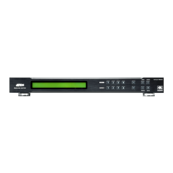
VM6404H / VM6809H User Manual VM6809H Front View Component Description LCD Display The LCD Display gives a quick view of all port connections, and shows the various options for configuring and operating the VM6809H. For full details, see Main Screen, page 19. -
Page 21: Vm6809H Rear View
Chapter 1. Introduction VM6809H Rear View Component Description Power Socket This is a standard 3-pin AC power socket. The power cord from an AC source plugs in here. Power Switch This is a standard rocker switch that powers the unit on and off. -
Page 22: Ir Remote Control
Press Input source pushbuttons 1–8 to select the Input source you want to display on a selected output 1–8 (see IR Remote Control Operation, page 38). The VM6404H’s IR remote control only supports use the 1-4 Input and Note: 1-4 Output pushbuttons. -
Page 23: Hardware Setup
Keyboard Power On function. Rack Mounting The VM6404H / VM6809H can be mounted in a 19” (1U) system rack. For the most convenient front panel pushbutton configuration and operation at the local site, mount the unit at the front of the rack, as follows: 1. - Page 24 VM6404H / VM6809H User Manual VM6809H 2. Position the unit in the front of the rack and align the holes in the mounting brackets with the holes in the rack. 3. Screw the mounting brackets to the rack.
-
Page 25: Grounding
To prevent damage to your installation, it is important that all devices are properly grounded. 1. Use a grounding wire to ground the VM6404H / VM6809H by connecting one end of the wire to the grounding terminal, and the other end of the wire to a suitable grounded object. -
Page 26: Cable Connection
4. Connect the IR Receiver into the IR port (for VM6404H). 5. (Optional) If you are using the Browser Operation features (see Browser Operation, page 41), plug a Cat 5e cable from the LAN into the VM6404H / VM6809H’s Ethernet port. -
Page 27: Installation Diagram
Chapter 2. Hardware Setup Installation Diagram VM6404H VM6809H... - Page 28 VM6404H / VM6809H User Manual This Page Intentionally Left Blank...
-
Page 29: Front Panel Configuration
Chapter 3 Front Panel Configuration Overview The VM6404H / VM6809H can be configured and operated locally via the front panel LCD/pushbuttons and IR Remote Control (for VM6404H only); remotely over a standard TCP/IP connection via graphical user interface (GUI) using a web browser; via a remote terminal session using Telnet; or by a RS- 232 serial controller. -
Page 30: Enter Password
If the Password screen / LCD Menu fails to load, an error message displays. Reset the unit and try again. If you are accessing the VM6404H / VM6809H for the first time, the Password screen appears as soon as the LCD loading process is done. Enter the default password 1234 to continue to the Main Screen (see Main Screen, page 19). -
Page 31: Main Screen
Chapter 3. Front Panel Configuration Main Screen The Main Screen shows the Input ports (1-4 or 1-8) in the top row, which are tied to the Output ports shown in sequential order (1-4 or 1-9) at the bottom row. INPUT 1 2 3 4 OUTPUT 1 2 3 4... - Page 32 VM6404H / VM6809H User Manual 2. To disconnect an Output port from an Input port, press the corresponding Output port pushbutton. In the example below, Output port 2 has been disconnected from Input port 3. To switch to another Input port, press any Input port pushbutton. The Output port LED(s) tied to the said Input port will flash.
-
Page 33: Output Port Selection
Chapter 3. Front Panel Configuration Output Port Selection Use the Output Port pushbuttons to select the Output port you want to configure. INPUT 1 2 3 4 OUTPUT 1 2 3 4 To select which output display corresponds to each input source device, do the following: 1. - Page 34 VM6404H / VM6809H User Manual 4. To switch Output ports 2, 3 and 4 to another Input port (and disconnect it from Input port 2), press another Input port pushbutton to which you want them tied. In the example below, Input port 3 has been pressed and is now connected to Output ports 2, 3 and 4.
-
Page 35: Lcd Menu Organization
Save to a Profile No. 01–08 (VM6404H); 01-17 (VM6809H) Play/Stop the Profile Schedule Turn Video Wall Off Note: Note: 1. The highlighted values are the default settings of the VM6404H / VM6809H. 2. The Audio Extract is only supported by VM6809H. -
Page 36: Menu Pushbutton
The values in the LCD Menu are read-only and can be edited via the Browser GUI (Network, page 73). IP Address / Subnet Mask To view the VM6404H / VM6809H’s IP address and Subnet Mask, do the following: 1. From the Menu page, press 1 to see the IP Setting submenu. The IP address and Subnet Mask are then shown. -
Page 37: Gateway
Chapter 3. Front Panel Configuration Gateway To view the VM6404H / VM6809H’s gateway address, do the following: 1. From the Menu page, press 1 to see the IP Setting submenu, then press 8 or Next to get to the next page. The gateway address displays. -
Page 38: Serial Port Setting
VM6404H / VM6809H User Manual Serial Port Setting To configure the VM6404H / VM6809H’s baud rate for its serial port connection, select Serial Port Setting from the Menu page. 1: IP Setting 2: Serial Port Setting : Next Baud Rate To set the VM6404H / VM6809H’s baud rate, do the following:... -
Page 39: Operation Mode
Output Resolution To configure the VM6404H / VM6809H’s operation mode settings from the Main Screen, use the Menu pushbutton to access the Menu page, press 8 or Next to navigate to the next page, then press pushbutton 1 to access the Operation Mode page. -
Page 40: Cec
3: Remix Uses the EDID of each connected display according to its connection when the VM6404H / VM6809H is first powered on, or immediately after pressing 3 to select the Remix option. 4: Customized This mode features an EDID Wizard that allows user-defined EDID configurations for optimum output. -
Page 41: Osd
The On-Screen Display or OSD feature enables real-time text updates to appear on the display device’s screen for any configuration changes made to the Output port via the VM6404H / VM6809H’s front panel, IR remote control or Browser GUI. To configure the OSD setting for each output port, do the following: 1. -
Page 42: Output Status
VM6404H / VM6809H User Manual Output Status To configure the Output Status settings for each output port, do the following: 1. From the Operation Mode page, press 8 or Next to go to the next page, then press pushbutton 2:... - Page 43 Chapter 3. Front Panel Configuration 2. VM6404H: From the Output Status page, press 2 to select Output Resolution. 1: Video 2: Output Resolution VM6809H: From the Output Status page, press 8 to go to the next page, and press 1 to select Output Resolution.
- Page 44 VM6404H / VM6809H User Manual To configure the Audio Extract settings for VM6809H, do the following: 1. From the Operation Mode page, press 8 or Next to go to the next page, and then press pushbutton 2: 1: OSD Prev 2: Output Status 2.
-
Page 45: Security Mode
Chapter 3. Front Panel Configuration Security Mode The Security Mode page allows users to manage the VM6404H / VM6809H’s security-related settings. Three security modes are available: None, Password Enable and Lock Screen. The VM6404H / VM6809H’s password can also be changed here. -
Page 46: Change Password
New Password: * * * * 4. Re-enter the new password in the following screen. The new password is applied by the VM6404H / VM6809H immediately. Re-enter New Password: * * * * If the password you entered does not match the one entered in the previous screen, an error message appears. -
Page 47: Save To A Profile
Chapter 3. Front Panel Configuration Save to a Profile The switch allows users to store up to 8 (VM6404H; numbered P1-P8) or 17 (VM6809H; numbered P1-P17) different connection profiles that can be saved and recalled later. The active Input-to-Output port connections on the LCD Main Screen is the configuration saved to a profile. -
Page 48: Play / Stop The Profile Schedule
VM6404H / VM6809H User Manual Play / Stop the Profile Schedule The final option in the menu allows users to play or stop the selected profile schedule (to learn more about switching between connection profiles, see Profile Pushbutton, page 37). -
Page 49: Profile Pushbutton
This feature is only available while a schedule is playing. Press the Cancel pushbutton to exit Note: If there are no profiles configured on the VM6404H / VM6809H device, an error message “No Available Profile” is displayed when the Profile pushbutton is pressed. -
Page 50: Ir Remote Control Operation
Output displays simultaneously Before using the remote control, a user must first plug the IR External Receiver into the rear panel of the VM6404H and place the receiver where the IR signal can be reached (see IR Port, page 7). -
Page 51: Power On/Off All Output Displays
Chapter 3. Front Panel Configuration Power on/off all Output displays To power on/off all Output displays simultaneously, with the remote control, do the following: 1. Press the ON or OFF pushbutton.* 2. Repeat step 1 to simultaneously change back the power status of all Output ports, to on or off, respectively. - Page 52 VM6404H / VM6809H User Manual This Page Intentionally Left Blank...
-
Page 53: Browser Operation
For full details, see the sections that follow. Logging In To access the GUI, type the VM6404H / VM6809H’s IP address into the address bar of any browser. If a Security Alert dialog box appears, accept the certificate –... -
Page 54: Main Page
VM6404H / VM6809H User Manual Main Page The Main Page opens to the Profile List. This is where you configure the input to output connections by creating profiles. The page is divided into three parts: the Menu Bar, Profile List, and Profile Scheduling. -
Page 55: Profile List
Profile List The Profile List lets you configure the input to output port connections by creating profiles to use. You can store up to 8 (VM6404H) or 17 (VM6809H) differently configured profiles that can be saved and played by two methods: locally via the unit’s front panel pushbuttons and via the web GUI. - Page 56 VM6404H / VM6809H User Manual (Continued from previous page.) 3. For VM6809H, select a template and click Apply to save your configuration or click Skip to enter the Connection Profile (page 53). 4. Configure the input to output connections for a Digital Signage (page 53) or Video Wall (page 56) profile.
- Page 57 Chapter 4. Browser Operation 7. The profile appears in the large Play window and the connections start: VM6404H VM6809H Note: More information about Profile List page options are provided on the next page.
-
Page 58: Importing/Exporting A Profile
To export the VM6404H / VM6809H’s connection profiles, do the following: 1. Click Export Profiles. A configuration file will then begin downloading. To import connection profiles to the VM6404H / VM6809H, do the following: 1. Click Import Profiles. 2. Browse to the configuration file, select it and click Open. -
Page 59: Profile List Options
Chapter 4. Browser Operation Profile List Options Clicking a Profile or the Play window opens a pop-up menu with options. VM6404H VM6809H... -
Page 60: Profile
VM6404H / VM6809H User Manual Profile Option Description Apply Click Apply to put the profile in the Play window. This allows you to start the profile connections. Edit Click Edit to configure the profile's input to output connections. Play Window... -
Page 61: Change Input
Chapter 4. Browser Operation Change Input Clicking on the Change Input button opens a pop-up window with options. Option Description Click “-” or “+” to zoom out or zoom in the layout. Click to fit the layout screen to the default view. Drag from the Port List on the right side and drop on any display of the layout to set/change the input source. -
Page 62: Other
VM6404H / VM6809H User Manual Other Option Description Show OSD Check Show OSD to show text updates that appear on the display when configuration or port changes are made. Mute All Check Mute All to mute the audio for all ports. -
Page 63: Profile Scheduling
Chapter 4. Browser Operation Profile Scheduling Profile Scheduling is located below the Profile List. Scheduling allows you to queue and play connection profiles in the indicated sequence for a specific amount of time. Option Description Click to edit profile schedule. Click to play profile schedule. - Page 64 VM6404H / VM6809H User Manual After selecting Edit, you will be presented with the following options. Option Description Click to add profiles to the schedule in the order to be played, left to right, then set the amount of time each profile plays.
-
Page 65: Connection Profiles
The Digital Signage feature can be set via the Video Wall profile by selecting one or more Output ports and the Video Input source. The settings are the same as VM6404H Digital Signage Profile. The displays of the selected Output ports can be physically installed in different locations for Digital... -
Page 66: Output Icon
VM6404H / VM6809H User Manual Output Icon Option Description Output Icon Click an Output icon(s) to highlight it in green and use the Select Source menu to set the video options (see Select Source below). The large number is the Video Input port selected for the display. -
Page 67: Grid View
Chapter 4. Browser Operation Grid View The Grid View allows you to select the Input to Output connections using a simple grid. Select a box to coordinate Input Ports to Output Ports. By default, ports will be aligned so that i01 will correspond to o01, etc. Uncheck a box to disable the video for that Output Port. -
Page 68: Video Wall Profile
VM6404H / VM6809H User Manual Video Wall Profile Each blank icon represents an Output port and the connected display. Use the icons to create Independent and Grouped Outputs. Independent Outputs will display video on a single monitor. Grouped Outputs will display video across multiple monitors as one large screen. - Page 69 Chapter 4. Browser Operation next to Display Layout _1 to create additional layouts under the same profile. Click the PEN icon or name to edit the profile name. Click Select All to select all outputs. Click Unselect All to unselect all outputs. Click Test to play current profile without saving.
-
Page 70: Number Of Displays / Output Order / Bezel Dimensions
VM6404H / VM6809H User Manual Number of Displays / Output Order / Bezel Dimensions VM6404H cccccccccccccccccccccccVM6809H Option Description Number of Use the Horizontal and Vertical drop-down menu to select the Displays number of displays that make up the video wall (a maximum of 64 are supported). -
Page 71: Null Input
Chapter 4. Browser Operation Null Input Option Description Null Icon Click Null Input icons to highlight icons in green and use the Display Preferences menu to set the video options (see Display Preferences, page 61). Select a single icon to set the Output and Video Input for an independent display (see Independent Output, page 59). -
Page 72: Grouping
VM6404H / VM6809H User Manual Grouping Option Description Grouping Click multiple icons to Group Outputs (highlighted in green) and →|← click to group the displays into one screen*. Use the Display Preferences menu to select the Video Input for the group - each Output icon in the Group will appear with the same Video Input number and icon color (see Group, page 60). -
Page 73: Display Preferences
Chapter 4. Browser Operation Display Preferences Option Description Display Click Output icons for the Display Preferences menu to appear– to Preferences select the Output and/or Video Input port. Output Use the drop-down menu to select the Output port (Independent and single Blank icons only). If you select multiple displays the output ports selected will appear here. - Page 74 VM6404H / VM6809H User Manual The Group will show Video Input 01 across both displays as one large screen. The Independent displays will show the video from their own Video Input – 03 and 04. Add Display Layouts to create separate video walls (see Video Wall...
-
Page 75: Output Options
Chapter 4. Browser Operation Output Options The Output Options page is used to configure HDMI Video options. The Output Options page for VM6809H can be found in the Video tab under Settings. HDMI Video Options HDMI Video Options allow you to set Seamless Switch™ options which determine how a display performs when the input port is changed. - Page 76 VM6404H / VM6809H User Manual Use the drop-down menu to apply to all ports, or ON/OFF button to enable/disable Transitions per port. Period: Sets the fade speed for the Transition option. Use the drop-down menu to apply an option (Slow, Normal, or Fast) to all ports, or lower drop-down menus to apply options per port.
-
Page 77: System Settings
Chapter 4. Browser Operation System Settings Click the Settings link from the Main page for the System Settings to open on the General page: The General page allows you to edit Baud, Language and Fan settings and view device information. The User Account page allows you to add and edit user accounts. - Page 78 VM6404H / VM6809H User Manual The Read Status page lists the status overview of the Video Matrix Switch, including System Network, Device Info, Video Connection, Audio Connection, CEC, OSD, and Output Resolution. Click Back to Profile List to return to the Main page.
-
Page 79: General
Fan Status This section displays the fan status for Video Matrix Switches. The VM6404H / VM6809H also includes a drop-down menu which allows for manual selection of fan speed. Note: If the fans have stopped working, they will appear as follows. -
Page 80: Other
VM6404H / VM6809H User Manual Other Use the Language drop-down menu to select a preferred user interface language. Options include: English, French, German, Italian, Japanese, Korean, Portuguese, Russian, Spanish, Simplified Chinese and Traditional Chinese. -
Page 81: User Account
Note: This is an Administrator only function. Add account– Click the Add account button to add another user to the list. The VM6404H / VM6809H supports up to 32 users and allows up to 16 concurrent logins (see page 70 for more details). -
Page 82: Add Account
Click Create User to save the data. Click Cancel to discard the changes and exit. If a user is logged into the VM6404H / VM6809H’s GUI, their user settings cannot be edited, and the fields in this screen are grayed out. -
Page 83: Permission Level
The three available permission levels are as follows: Administrator – this level provides full access and control of the VM6404H / VM6809H, in addition to full User Management privileges. Advanced User – this level provides full access and control with no User Management privileges. -
Page 84: Port Name
VM6404H / VM6809H User Manual Port Name The Port Name page lets you name the input and output ports for easy identification. To name an Input/Output port, enter a descriptive name of up to 16 multi-language characters (excluding :;=[]+=/?\|) in the corresponding field and click Save. -
Page 85: Network
Telnet settings for connecting to the VM6404H / VM6809H. Enable DHCP to allow the DHCP server to assign an IP address to the VM6404H / VM6809H. Select Disable to enter your own static IP address settings for the device. Click Cancel to use the following default values: IP Address –... -
Page 86: Edid
The EDID Settings page lets users view and select an EDID Mode so that the VM6404H / VM6809H can use the best resolution for its display(s). Note: The EDID Mode can also be selected via the Front Panel pushbuttons –... -
Page 87: Edid Mode
In the left panel of the page, users can select a pre-configured EDID Mode using the EDID Mode radio buttons. Select the EDID Mode to use and click Apply. The VM6404H / VM6809H uses the settings configured for that EDID mode. -
Page 88: Customized Mode
Retrieve EDID: Click and a pop-up window appears to retrieve the EDID settings of a stored EDID configuration: Customized EDID (01- 04 / 01-09), ATEN Default, or Display port (the EDID of the display connected to the output port). The right panel displays a summary of the acquired EDID settings that you can edit. -
Page 89: Edid & Cea Description
Chapter 4. Browser Operation EDID & CEA Description The right panel of the screen lets users view the configuration of the EDID and CEA Modes selected: From the left column, click the option that you want to view and/or edit. There are two categories: EDID (Extended Display Identification Data) and CEA (Consumer Electronics Association). -
Page 90: Customized Edid Parameters
VM6404H / VM6809H User Manual Customized EDID Parameters The EDID structure is comprised of 128 bytes in total – each heading shown in the left column corresponds to a specific number of bytes. The pages for the pre-configured EDID Modes (Port 1, Default and Remix) cannot be edited. - Page 91 Chapter 4. Browser Operation Standard Timings This page shows eight resolutions/timings that display devices can support in addition to those listed in the Established Timings page. Select the H Active Pixel from the drop-down menu. Select the Aspect Ratio from the drop-down menu. Click Save to apply the changes.
- Page 92 VM6404H / VM6809H User Manual Monitor Description This screen lets you specify the viewing specifications, namely horizontal and vertical scan ranges and pixel clock rate, of your monitor/display device. Enter the values that correspond to your device and click Save to apply the...
-
Page 93: Cea Settings
Chapter 4. Browser Operation CEA Settings CEA is an extension data of the EDID structure, which further extends the standard definitions of EDID to support advanced features of monitors/display devices. Display Support This screen describes the display’s basic digital components. Select the YCbCr mode applicable to your display and click Save. -
Page 94: Video Data
VM6404H / VM6809H User Manual Video Data This screen lists additional video resolution/timing displays that may be supported by other devices, other than PC monitors (for example, 1080i). Select the native resolution of the attached display device. Select the resolutions, refresh rate, and aspect ratio that work with the attached monitor/display device. - Page 95 Chapter 4. Browser Operation Audio Data This screen lets you select advanced audio configurations for your device. Use the drop down menu to select the Audio Format (1~6) applicable to your audio output device, and click Save to apply the changes. Detail Timing / Display Description This screen gives more video resolution options, and provides resolution/ timing details (in addition to those specified in the EDID structure).
-
Page 96: Maintenance
This will ensure the GUI refreshes and functions properly. To back up the VM6404H / VM6809H’s system settings, do the following: 1. Click Backup. A configuration file will then begin downloading. -
Page 97: Hdcp
Chapter 4. Browser Operation HDCP The HDCP page lets users view and set HDCP key settings between input and output ports for digital copy protection and to ensure Seamless Switch™ functionality between different devices. This is an Administrator and Advanced User only function. Input Here users can select whether port capability is HDCP 2.2, HDCP 1.4 or non- HDCP enabled, either individually or by applying one setting to all ports. -
Page 98: Osd/Cec
VM6404H / VM6809H User Manual OSD/CEC The OSD/CEC page lets users view and set OSD and CEC settings for all ports. OSD: Sets the default OSD option for the port. When OSD is on, real- time text updates appear on the display for 10 seconds when configuration and port changes are made to its output. -
Page 99: Telnet Operation
The VM6404H / VM6809H can be operated and configured via a remote terminal session using Telnet. To log into the VM6404H / VM6809H by means of a Telnet session, do the following: 1. On your computer, open a terminal (command line) session. -
Page 100: Ip - Set Network Settings
VM6404H / VM6809H User Manual 2. IP – Set network settings Set IP Address Old IP Address: 192.168.0.60 Old IP Subnet Mask: 255.255.255.0 Old Gateway Address: 192.168.0.1 New IP Address: Set Subnet Mask Old IP Address: 192.168.0.60 Old IP Subnet Mask: 255.255.255.0 Old Gateway Address: 192.168.0.1... -
Page 101: Im - Set Ip Subnet Mask
Chapter 4. Browser Operation 3. IM – Set IP subnet mask Old IP subnet mask: 255.255.255.0 4. LO – Load connections from profile LO 01 Load profile 01 OK. 5. PW – Change password Old password: ******** New password: 6. RI – Read what input is connected to nn output RI 01 Input port 02 04 is connected to output port 01 7. -
Page 102: 11. Ti - Set Timeout
VM6404H / VM6809H User Manual Save the current connections into profile 01 11. TI – Set timeout TI 30 Set 30 minute timeout 12. VR – Software version information Software version 1.0. Note: All RS-232 commands in this manual are also applicable in Telnet mode, see RS-232 Commands, page 91. -
Page 103: Rs-232 Commands
Chapter 5 RS-232 Commands Serial Control Protocol Commands The VM6404H / VM6809H’s built-in bi-directional RS-232 serial interface allows system control through a high-end controller or PC. RS232 Pin Assignment Description Description Not connected Not connected Not connected Not connected Not connected... -
Page 104: Verification
VM6404H / VM6809H User Manual Verification After entering a command, a verification message appears at the end of the command line as follows: Command OK - indicates that the command is correct and successfully performed by the switch Command incorrect - indicates that the command has the wrong format... -
Page 105: Switch Port Command
Chapter 5. RS-232 Commands Switch Port Command The Switch Port command allows you to switch ports on the VM6404H / VM6809H. The formula for the Switch command is as follows. VM6404H: Command + Input + Number + Output + Number + Control + [Enter]... - Page 106 VM6404H / VM6809H User Manual Control Description Turn on the display Turn off the display Next Port Previous Port Note: 1. By default, input port 01 is tied to output port 01; input port 02 is tied to output port 02; and so on until port 04 (i.e., o01 i01, o02 i02).
-
Page 107: Edid Mode Command
Port 1, and pass it to the video source. remix Implement the EDID of each connected display according to its connection when the VM6404H / VM6809H is first powered on, or immediately after selecting the Remix option. default Implements ATEN’s default EDID. (default) -
Page 108: Mute Command
VM6404H / VM6809H User Manual Mute Command Mute allows you to enable or disable an output port(s) audio. The formula for the Mute command is as follows: VM6404H: Command + Output + Number + Control + [Enter] VM6809H: Command + Output + Number + Group + Control + [Enter] 1. - Page 109 Chapter 5. RS-232 Commands The following table lists the available Mute commands: Output Command Group Control Enter Description Port mute normal [Enter] Audio on for output port yy console (yy:01~04 or 01~09, *) mute normal [Enter] Audio off for output port yy (default) console (yy:01~04 or 01~09, *)
-
Page 110: Cec Command
VM6404H / VM6809H User Manual CEC Command Consumer Electronics Control (CEC) allows interconnected HDMI devices to communicate with and respond to the same remote control. The formula for the CEC command is as follows: Command + Output + Number + Control + [Enter] 1. -
Page 111: Scaling Command
Chapter 5. RS-232 Commands Scaling Command The Scaling command allows you to set a resolution for scaling the display connected to an output port. The formula for the Scaling command is as follows: Command + Output + Number 1 + Horizontal Resolution + Number 2 + Vertical Resolution + Number 3 + Frequency + Number 4 + Control + [Enter] 1. - Page 112 VM6404H / VM6809H User Manual Resolution Number Description vvvv Vertical resolution Frequency Description freq Frequency command for scaling Frequency Number Description Frequency resolution Control Description Turn off the scaling function (by pass mode) native Map display's native resolution for scaling (default) Note: 1.
- Page 113 Chapter 5. RS-232 Commands Horiz Vertic Port Comm Outp ontal Numb Numb Frequ Numb Contr Numb Enter Description Resol Resol ency ution ution scaling 1920 1080 freq [Enter Scale output port yy to 1920x1080@ 60Hz yy:01~04, 01~09, or * scaling 1280 freq [Enter...
- Page 114 VM6404H / VM6809H User Manual Horiz Vertic Port Comm Outp ontal Numb Numb Frequ Numb Contr Numb Enter Description Resol Resol ency ution ution scaling 1280 freq [Enter Scale output port yy to 1280x800@6 yy:01~04, 01~09, or * scaling freq...
-
Page 115: Framsync Command
Chapter 5. RS-232 Commands FramSync Command The FramSync command allows you enable or disable the Frame Synchronization function for VM6809H. The formula for the Scaling command is as follows: Command + Control + [Enter] For example, to enable the Frame Synchronization function, type: frsync on [Enter] The following tables show the possible values for the FramSync command: Command... -
Page 116: Echo Command
VM6404H / VM6809H User Manual Echo Command The Echo function updates the RS-232 controller when operations are made via the front panel pushbuttons, web browser, or telnet. The changes echo back to the RS-232 controller to keep the settings in sync with the device. -
Page 117: Black Screen Command
Chapter 5. RS-232 Commands Black Screen Command The Black Screen command turns a display screen black when no source signal is detected. This prevents the display from showing the default blue or other color used when no source signal is detected. The formula for the Black Screen command is as follows: Command + Control + [Enter] 1. -
Page 118: Read Command
[Enter] View information about the device Reset Command The Reset command allows you to reset the VM6404H / VM6809H to the default factory settings. The formula for the Reset command is as follows: Command + [Enter] The following tables show the possible values for the Reset command:... -
Page 119: Baud Rate Command
Baud Rate Command The Baud Rate command allows you to set the RS-232 data rate for the VM6404H / VM6809H to use. Options are 9600, 19200 (default) 38400 and 115200. The formula for the Baud Rate command is as follows: Command + Control + [Enter] 1. -
Page 120: Save/Load Profile Command
VM6404H / VM6809H User Manual Save/Load Profile Command The Save/Load Profile command allows you to save and load connection profiles. Saving profiles will save the connections currently in use. The formula for the Save/Load Profile command is as follows: Command + Profile + Number + Control + [Enter] 1. -
Page 121: Osd Command
Chapter 5. RS-232 Commands OSD Command To enable or disable the On-Screen Display (OSD) use the following command: Command + Control + [Enter] 1. For example, to enable the OSD, type: osd on [enter] The following tables show the possible values for the OSD command: Command Description Enable / Disable the OSD... -
Page 122: Alert Command
VM6404H / VM6809H User Manual Alert Command To trigger a warning when issues arise for a specific input port, use the following command: Command + Input + Number + Control + [Enter] 1. For example, to enable the basic Alert function for input port 1, type:... -
Page 123: Fan Speed Command
Chapter 5. RS-232 Commands Fan Speed Command To setup fan speed, use the following command: Command + Speed Value + [Enter] For example, to set the fans to operate at high speed, type: fan high [Enter] The following tables show the possible values for the Fan Speed command: Command Description Fan Speed command... -
Page 124: Rs-232 Pin Assignment
VM6404H / VM6809H User Manual RS-232 Pin Assignment Description Description Not connected Not connected Not connected Not connected Not connected Not connected... -
Page 125: Appendix
Appendix Safety Instructions General Read all of these instructions. Save them for future reference. Follow all warnings and instructions marked on the device. This product is for indoor use only. Do not place the device on any unstable surface (cart, stand, table, etc.). If the device falls, serious damage will result. - Page 126 VM6404H / VM6809H User Manual If an extension cord is used with this device make sure that the total of the ampere ratings of all products used on this cord does not exceed the extension cord ampere rating. Make sure that the total of all products plugged into the wall outlet does not exceed 15 amperes.
-
Page 127: Rack Mounting
Appendix Rack Mounting Before working on the rack, make sure that the stabilizers are secured to the rack, extended to the floor, and that the full weight of the rack rests on the floor. Install front and side stabilizers on a single rack or front stabilizers for joined multiple racks before working on the rack. -
Page 128: Technical Support
VM6404H / VM6809H User Manual Technical Support International For online technical support – including troubleshooting, documentation, and software updates: http://eservice.aten.com For telephone support, see Telephone Support, page iv: North America Email Support support@aten-usa.com Online Troubleshooting http://www.aten-usa.com/support Technical Documentation Support Software Updates... -
Page 129: Specifications
Appendix Specifications Function VM6404H VM6809H Video Input Interface 4 x HDMI Type A 8 x HDMI Type A Female (Black) Female (Black) Impedance 100 Ω Max. Distance 1.8 m Video Interface 4 x HDMI Type A 9 x HDMI Type A... -
Page 130: Limited Warranty
VM6404H / VM6809H User Manual Function VM6404H VM6809H Physical Housing Metal Properties Weight 4.72 kg 7.05 kg Dimensions (L x W x 43.24 x 30.73 x 4.40 cm 43.24 x 45.03 x 4.40 cm 1 pcs Carton Lot Limited Warranty...
Need help?
Do you have a question about the VM6404H and is the answer not in the manual?
Questions and answers