
Subscribe to Our Youtube Channel
Related Manuals for ASROCK Rack TRX40D8-2N2T


Summary of Contents for ASROCK Rack TRX40D8-2N2T
- Page 1 TRX40D8-2N2T User Manual Version 1.0 Published July 2020 Copyright©2020 ASRock Rack INC. All rights reserved.
- Page 2 In no event shall ASRock Rack, its directors, officers, employees, or agents be liable for any indirect, special, incidental, or consequential damages (including damages for loss of profits, loss of business, loss of data, interruption of business and the like), even if ASRock Rack has been advised of the possibility of such damages arising from any defect or error in the documentation or product.
- Page 3 Contact Information If you need to contact ASRock Rack or want to know more about ASRock Rack, you’re welcome to visit ASRock Rack’s website at www.ASRockRack.com; or you may contact your dealer for further information. ASRock Rack Incorporation 6F., No.37, Sec. 2, Jhongyang S. Rd., Beitou District,...
-
Page 4: Table Of Contents
Contents Chapter 1 Introduction Package Contents Specifications Unique Features Motherboard Layout Onboard LED Indicators I/O Panel Block Diagram Chapter 2 Installation Screw Holes Pre-installation Precautions Installing the CPU and Heatsink Installing the CPU Cooler Installation of Memory Modules (DIMM) Expansion Slots (PCI Express Slots) Onboard Headers and Connectors Unit Identification purpose LED/Switch Driver Installation Guide... - Page 5 Main Screen Advanced Screen OC Tweaker 3.4.1 CPU Configuration 3.4.2 Chipset Configuration 3.4.3 Storage Configuration 3.4.4 ACPI Configuration 3.4.5 Super IO Configuration 3.4.6 Serial Port Console Redirection 3.4.7 H/W Monitor 3.4.8 USB Configuration 3.4.9 PCI Subsystem Settings 3.4.10 AMD Mem Configuration Status 3.4.11 AMD CBS 3.4.12 AMD PBS 3.4.13 AMD Overclocking...
- Page 6 3.7.1 CSM Parameters Exit Screen Chapter 4 Software Support Install Operating System Support CD Information 4.2.1 Running The Support CD 4.2.2 Drivers Menu 4.2.3 Utilities Menu 4.2.4 Contact Information Chapter 5 Troubleshooting Troubleshooting Procedures Technical Support Procedures Returning Merchandise for Service...
-
Page 7: Chapter 1 Introduction
In case any modifications of this manual occur, the updated version will be available on ASRock Rack website without further notice. You may find the latest memory and CPU support lists on ASRock Rack website as well. ASRock Rack’s Website: www.ASRockRack.com If you require technical support related to this motherboard, please visit our website for specific information about the model you are using. -
Page 8: Specifications
1.2 Specifications TRX40D8-2N2T MB Physical Status Form Factor Dimension 12'' x 9.6'' (30.5 cm x 24.4 cm) Processor System Supports AMD Ryzen™ Threadripper™ TR4+ Series Processors Socket AMD Socket TR4 4094P Chipset AMD TRX40 System Memory Capacity - 8 x 288-pin DDR4 DIMM slots - Supports up to 256GB DDR4 ECC &... - Page 9 TRX40D8-2N2T Management BMC Controller ASPEED AST2500 : IPMI (Intelligent Platform Management Interface) 2.0 with Ikvm and vMedia support IPMI Dedicated 1 x Realtek RTL8211E for dedicated management GLAN Features Gracphics Controller ASPEED AST2500 VRAM DDR4 16MB Rear Panel I/O PS/2 KB/mouse...
- Page 10 32Mb AMI UEFI Legal BIOS BIOS Features - Plug and Play (PnP) - ACPI 2.0 Compliance Wake Up Events - SMBIOS 2.8 Support - ASRock Rack Instant Flash Hardware Monitor Temperature - CPU Temperature Sensing - System Temperature Sensing - Card side Temperature Sensing...
- Page 11 TRX40D8-2N2T If you install Intel® LAN utility or Marvell SATA utility, this motherboard may fail Win- dows® Hardware Quality Lab (WHQL) certification tests. If you install the drivers only, it will pass the WHQL tests.
-
Page 12: Unique Features
. With this utility, you can press the <F6> key during the POST or the <F2> key to enter into the BIOS setup menu to access ASRock Rack Instant Flash. Just launch this tool and save the new BIOS file to your USB flash drive, floppy disk or hard drive, then you can update your BIOS only in a few clicks without preparing an additional floppy diskette or other complicated flash utility. -
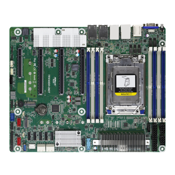
Page 13: Motherboard Layout
TRX40D8-2N2T 1.4 Motherboard Layout 24.4cm (9.6 in) UID1 DDR4_D1 (64 bit, 288-pin module), Blue DDR4_D2 (64 bit, 288-pin module). White ATX12V2 ATX12V1 FRNT_VGA1 DDR4_C1 (64 bit, 288-pin module), Blue ATXPWR1 DDR4_C2 (64 bit, 288-pin module), White PSU_SMB1 10G_LAN3 DDR4_A2 (64 bit, 288-pin module), White... - Page 14 Description 2 x 288-pin DDR4 DIMM Slots (DDR4_C2, DDR4_D2, White)* 2 x 288-pin DDR4 DIMM Slots (DDR4_C1, DDR4_D1, Blue)* ATX 12V Power Connector (ATX12V2) ATX 12V Power Connector (ATX12V1) ATX Power Connector (ATXPWR1) PSU SMBus (PSU_SMB1) AMD Socket TR4 4094P 2 x 288-pin DDR4 DIMM Slots (DDR4_A2, DDR4_B2, White)* 2 x 288-pin DDR4 DIMM Slots (DDR4_A1, DDR4_B1, Blue)* USB 3.2 Gen1 Header (USB3_6_7)
- Page 15 TRX40D8-2N2T Description Intelligent Platform Management Bus Header (IPMB1) BMC SMBus Header (BMC_SMB1) Front LAN LED Connector (LED_LAN3_4) Non Maskable Interrupt Button (NMI_BTN1) M.2 Socket (M2_2) (Type 2230/2242/2260/2280/22110) SPI TPM Header (TPM_BIOS_PH1) Front VGA Header (FRNT_VGA1) *For DIMM installation and configuration instructions, please see p.23 (Installation of Memory Modules...
-
Page 16: Onboard Led Indicators
DDR4_C2 (64 bit, 288-pin module), White DDR4_A2 (64 bit, 288-pin module), White DDR4_A1 (64 bit, 288-pin module), Blue DDR4_B2 (64 bit, 288-pin module), White DDR4_B1 (64 bit, 288-pin module), Blue FAN1 BIOS TRX40 FAN2 Super TRX40D8-2N2T FAN3 AST2500 CMOS FAN4 Battery RoHS FAN5 FAN6 NUT110_2... -
Page 17: I/O Panel
TRX40D8-2N2T 1.6 I/O Panel No. Description No. Description UID Switch (UID1) LAN RJ-45 Port (IPMI_LAN)* VGA Port (VGA1) 2.5G LAN RJ-45 Port (2.5G_LAN1)** USB 3.2 Gen1 Ports (USB3_1_2) 2.5G LAN RJ-45 Port (2.5G_LAN2)** PS/2 Mouse/Keyboard Port 10G LAN RJ-45 Port (LAN3)*** USB 3.2 Gen2 Port (USB31_TC_1) - Page 18 **There are two LEDs on each LAN port. Please refer to the table below for the LAN port LED indications. SPEED LED ACT/LIN K LED SPEED LED ACT/LIN K LED LAN Port 2.5G LAN Port (LAN1, LAN2) LED Indications Activity / Link LED Speed LED Status Description...
-
Page 19: Block Diagram
TRX40D8-2N2T 1.7 Block Diagram... -
Page 20: Chapter 2 Installation
Chapter 2 Installation This is an ATX form factor (12” x 9.6”, 30.5 cm x 24.4 cm) motherboard. Before you install the motherboard, study the configuration of your chassis to ensure that the motherboard fits into it. Make sure to unplug the power cord before installing or removing the motherboard. Failure to do so may cause physical injuries to you and damages to motherboard components. -
Page 21: Pre-Installation Precautions
TRX40D8-2N2T 2.2 Pre-installation Precautions Take note of the following precautions before you install motherboard components or change any motherboard settings. 1. Unplug the power cord from the wall socket before touching any components. 2. To avoid damaging the motherboard’s components due to static electricity, NEVER place your motherboard directly on the carpet or the like. -
Page 22: Installing The Cpu And Heatsink
2.3 Installing the CPU and Heatsink Unplug all power cables before installing the CPU. - Page 23 TRX40D8-2N2T...
- Page 24 Carr ier Frame with CPU Rail Frame Please make sure that the carrier frame with CPU is closely attached to the rail frame while inserting it. Install the orange carrier frame with CPU. Don’t separate them.
- Page 25 TRX40D8-2N2T...
-
Page 26: Installing The Cpu Cooler
2.4 Installing the CPU Cooler After you install the CPU into this motherboard, it is necessary to install a larger heatsink and cooling fan to dissipate heat. You also need to spray thermal grease between the CPU and the heatsink to improve heat dissipation. Make sure that the CPU and the heatsink are securely fastened and in good contact with each other. - Page 27 TRX40D8-2N2T...
-
Page 29: Installation Of Memory Modules (Dimm)
TRX40D8-2N2T 2.5 Installation of Memory Modules (DIMM) This motherboard provides eight 288-pin DDR4 (Double Data Rate 4) DIMM slots and supports Dual Channel Memory Technology. A single memory module should be installed in the Blue socket. CPU1 1 DIMM 2 DIMMS... - Page 30 The DIMM only fits in one correct orientation. It will cause permanent damage to the motherboard and the DIMM if you force the DIMM into the slot at incorrect orientation.
-
Page 31: Expansion Slots (Pci Express Slots)
TRX40D8-2N2T 2.6 Expansion Slots (PCI Express Slots) There are 4 PCI Express slots on this motherboard. PCIE slot: PCIE3, PCIE5 and PCIE7 (PCIE 4.0 x16 slot, from CPU) are used for PCI Express x16 lane width graphics cards. PCIE1 (PCIE 4.0 x8 slot, from CPU) is used for PCI Express x8 lane width graphics cards. -
Page 32: Onboard Headers And Connectors
2.7 Onboard Headers and Connectors Onboard headers and connectors are NOT jumpers. Do NOT place jumper caps over these headers and connectors. Placing jumper caps over the headers and connectors will cause permanent damage to the motherboard. System Panel Header C onnec t t he power sw itch, PLED+ PLED-... - Page 33 TRX40D8-2N2T Auxiliary Panel Header This header supports multiple (18-pin AUX_PANEL1) functions on the front panel, (see p.7, No. 22) including the front panel SMB, internet status indicator and chassis intrusion pin. A. Front panel SMBus connecting pin (6-1 pin FPSMB) This header allows you to connect SMBus (System Management Bus) equipment.
- Page 34 Serial ATA3 DOM The SATA3 DOM connectors SATA3 SATA2 Connectors support both a SATA DOM (SATA2) (Disk-On-Module) and a SATA (see p.7, No. 25) data cable for internal storage (SATA3) device. (see p.7, No. 20) USB 3.2 Gen1 Connector (USB3_5) (see p.7, No.
- Page 35 TRX40D8-2N2T Baseboard Management The header is used for the Controller SMBus Header SMBus devices. (5-pin BMC_SMB1) BMC_SMB_PRESENT_1_N (see p.7, No. 34) Power BMC_SMBCLK BMC_SMBDATA System Fan Connectors Please connect the fan cables to (4-pin FAN1) the fan connectors and match (see p.7, No.
- Page 36 TPM Header This connector supports (13-pin TPM1) Trusted Platform Module (see p.7, No. 30) (TPM) system, which can securely store keys, digital certificates, passwords, and data. A TPM system also helps enhance network security, protects digital identities, and ensures platform integrity. ALERT PSU SMBus PSU SMBus monitors the...
- Page 37 TRX40D8-2N2T Clear CMOS Pad This allows you to clear the (CLRMOS1) data in CMOS. To clear CMOS, (see p.7, No. 29) take out the CMOS battery and short the Clear CMOS Pad. Front VGA Header Please connect either end (10-pin FRN_VGA1) of VGA_2X5 cable to VGA (see p.7, No.
- Page 38 SPI TPM Header This connector supports SPI SPI_DQ2 SPI_CS0 (13-pin TPM_BIOS_PH1) Trusted Platform Module SPI_MISO RSMRST# (see p.7, No. 38) (TPM) system, which can SPI_TPM_CS# securely store keys, digital certificates, passwords, and data. A TPM system also helps TPM_PIRQ RST# enhance network security, SPI_MOSI protects digital identities, and...
-
Page 39: Unit Identification Purpose Led/Switch
TRX40D8-2N2T 2.8 Unit Identification purpose LED/Switch With the UID button, You are able to locate the server you’re working on from behind a rack of servers. Unit Identification When the UID button on the purpose LED/Switch front or rear panel is pressed,... -
Page 40: M.2_Ssd (Ngff) Module Installation Guide
2.10 M.2_SSD (NGFF) Module Installation Guide The M.2, also known as the Next Generation Form Factor (NGFF), is a small size and versatile card edge connector that aims to replace mPCIe. The M.2 Socket supports a M.2 PCI Express module up to Gen4 x4 (64 Gb/s). Installing the M.2_SSD (NGFF) Module Step 1 Prepare a M.2_SSD (NGFF) module... - Page 41 TRX40D8-2N2T Step 3 Move the standoff based on the module type and length. The standoff is placed at the nut location D by default. Skip Step 3 and 4 and go straight to Step 5 if you are going to use the default nut.
- Page 42 Step 6 Tighten the screw with a screwdriver to secure the module into place. Please do not overtighten the screw as this might damage the module. NUT2 NUT1...
-
Page 43: Chapter 3 Uefi Setup Utility
TRX40D8-2N2T Chapter 3 UEFI Setup Utility 3.1 Introduction This section explains how to use the UEFI SETUP UTILITY to configure your system. The UEFI chip on the motherboard stores the UEFI SETUP UTILITY. You may run the UEFI SETUP UTILITY when you start up the computer. Please press <F2> or <Del> during the Power-On-Self-Test (POST) to enter the UEFI SETUP UTILITY;... -
Page 44: Navigation Keys
3.1.2 Navigation Keys Please check the following table for the function description of each navigation key. Navigation Key(s) Function Description Moves cursor left or right to select Screens Moves cursor up or down to select items + / - To change option for the selected items <Tab>... -
Page 45: Main Screen
TRX40D8-2N2T 3.2 Main Screen Once you enter the UEFI SETUP UTILITY, the Main screen will appear and display the system overview. The Main screen provides system overview information and allows you to set the system time and date. -
Page 46: Advanced Screen
3.3 Advanced Screen In this section, you may set the configurations for the following items: OC Tweaker, CPU Configuration, Chipset Configuration, Storage Configuration, ACPI Configuration, Super IO Configuration, Serial Port Console Redirection, H/W Monitor, USB Configuration, PCI Subsystem Settings, AMD Mem Configuration Status, AMD CBS, AMD PBS, AMD Overclocking and Instant Flash. -
Page 47: Oc Tweaker
TRX40D8-2N2T 3.4 OC Tweaker In the OC Tweaker screen, you can set up overclocking features. Because the UEFI software is constantly being updated, the following UEFI setup screens and descriptions are for reference purpose only, and they may not exactly match what you see on your screen. - Page 48 Warning: S3 is not supported on systems where SMT is disabled. CPU Frequency and Voltage (VID) Change If this item is set to [Manual], the multiplier and voltage will be set based on user selection. Final result is depending on the CPU's capability. CPU Core (Per CCX) Frequency (MHz) Adjust processor boost frequency.
- Page 49 TRX40D8-2N2T Infinity Fabric freq. and Dividers Set Infinity Fabric Frequency and Dividers (FCLK). DRAM Information Browse the serial presence detect (SPD) for DDR4 modules. DRAM Timing Configuration Voltage Configuration Voltage Mode [OC]: Larger range voltage for overclocking. [STABLE]: Smaller range voltage for stable system.
- Page 50 PREM VDDCR_SOC_S5 (mV) Use this to configure the voltage of the PREM_VDDCR_SOC_S5. VPPM_AB (mV) Use this to configure the voltage of the VPPM_AB. VTT_DDR_AB offset (mV) Use this to configure the voltage of the VPPM_AB. VPPM_CD (mV) Use this to configure the voltage of the VPPM_CD. VTT_DDR_CD offset (mV) Use this to configure the voltage of the VPPM_CD.
-
Page 51: Cpu Configuration
TRX40D8-2N2T 3.4.1 CPU Configuration SVM Mode Enable/disable CPU Virtualization. -
Page 52: Chipset Configuration
3.4.2 Chipset Configuration Primary Graphics Adapter Select a primary VGA. Onboard VGA To enable or disable Onboard VGA. SPI/LPC/fTPM TPM switch To select. 0 - AMD CPU fTPM. 1 - LPC TPM. 2 - SPI TPM. Onboard I225 LAN1 To enable or disable Onabord LAN. Onboard I225 LAN2 To enable or disable Onabord LAN. - Page 53 TRX40D8-2N2T PCIE Slot 3 Link Width Use this item to set PCIE Slot3's Link Width. PCIE Slot 5 Link Width Use this item to set PCIE Slot5's Link Width. PCIE Slot 7 Link Width Use this item to set PCIE Slot7's Link Width.
-
Page 54: Storage Configuration
3.4.3 Storage Configuration SATA Controller(s) Use this item to enable or disable the SATA controllers. SATA Mode AHCI: Supports new features that improve performance. RAID: Combine multiple disk drives into a logical unit. SATA Hot Plug (ASM1601) SATA Hot Plug (ASM1061 A_SATA0_1) Enable/Disable Control. -
Page 55: Acpi Configuration
TRX40D8-2N2T 3.4.4 ACPI Configuration PCIE Devices Power On Allow the system to be waked up by a PCIE device and enable wake on LAN. Ring-In Power On Use this item to enable or disable Ring-In signals to turn on the system from the power- soft-off mode. -
Page 56: Super Io Configuration
3.4.5 Super IO Configuration Serial Port 1 Configuration Use this item to set parameters of Serial Port 1 (COM1). Serial Port Use this item to enable or disable the serial port. Serial Port Address Use this item to select an optimal setting for Super IO device. SOL Configuration Use this item to set parameters of SOL. -
Page 57: Serial Port Console Redirection
TRX40D8-2N2T 3.4.6 Serial Port Console Redirection COM1 / SOL Console Redirection Use this option to enable or disable Console Redirection. If this item is set to Enabled, you can select a COM Port to be used for Console Redirection. Console Redirection Settings Use this option to configure Console Redirection Settings, and specify how your computer and the host computer to which you are connected exchange information. - Page 58 Bits Per Second Use this item to select the serial port transmission speed. The speed used in the host computer and the client computer must be the same. Long or noisy lines may require lower transmission speed. The options include [9600], [19200], [57600] and [115200]. Data Bits Use this item to set the data transmission size.
- Page 59 TRX40D8-2N2T Redirect After POST When Bootloader is selected, then Legacy Console Redirection is disabled before booting to legacy OS. When Always Enable is selected, then Legacy Console Redirection is enabled for legacy OS. Default setting for this option is set to Always Enable.
-
Page 60: H/W Monitor
3.4.7 H/W Monitor In this section, it allows you to monitor the status of the hardware on your system, includ- ing the parameters of the CPU temperature, motherboard temperature, CPU fan speed, chassis fan speed, and the critical voltage. Watch Dog Timer This allows you to enable or disable the Watch Dog Timer. -
Page 61: Usb Configuration
TRX40D8-2N2T 3.4.8 USB Configuration Legacy USB Support Enable Legacy OS Support for USB 2.0 devices. Select UEFI Setup Only to support USB devices under the UEFI setup and Windows/Linux operating systems only. -
Page 62: Pci Subsystem Settings
3.4.9 PCI Subsystem Settings Above 4G Decoding Enable or disable 64bit capable Devices to be decoded in Above 4G Address Space (only if the system supports 64 bit PCI decoding). SR-IOV Support If system has SR-IOV capable PCIe Devices, this option Enables or Disables Single Root IO Virtualization Support... -
Page 63: Amd Mem Configuration Status
TRX40D8-2N2T 3.4.10 AMD Mem Configuration Status To display memory configuration (initialized by ABL) status. -
Page 64: Amd Cbs
3.4.11 AMD CBS The AMD CBS menu accesses AMD specific features. -
Page 65: Amd Pbs
TRX40D8-2N2T 3.4.12 AMD PBS The AMD PBS menu accesses AMD specific features. -
Page 66: Amd Overclocking
3.4.13 AMD Overclocking The AMD Overclocking menu accesses options for configuring CPU frequency and voltage. -
Page 67: Instant Flash
TRX40D8-2N2T 3.4.14 Instant Flash Instant Flash is a UEFI flash utility embedded in Flash ROM. This convenient UEFI update tool allows you to update system UEFI without entering operating systems ® first like MS-DOS or Windows . Just save the new UEFI file to your USB flash drive,... -
Page 68: Server Mgmt
3.5 Server Mgmt Wait For BMC Wait For BMC response for specified time out. BMC starts at the same time when BIOS starts during AC power ON. It takes around 90 seconds to initialize Host to BMC interfaces. -
Page 69: System Event Log
TRX40D8-2N2T 3.5.1 System Event Log SEL Components Change this to enable ro disable event logging for error/progress codes during boot. Erase SEL Use this to choose options for earsing SEL. When SEL is Full Use this to choose options for reactions to a full SEL. -
Page 70: Bmc Tools
3.5.2 BMC Tools Load BMC Default Settings Use this item to Load BMC Default Settings KCS Control Select this KCS interface state after POST end. If [Enabled] us selected, the BMC will remain KCS interface after POST stage. If [Disabled] is selected, the BMC will disable KCS interface after POST stage... -
Page 71: Bmc Network Configuration
TRX40D8-2N2T 3.5.3 BMC Network Configuration BMC Out of Band Access Enabled/Disabled BMC Out of band Access. Lan Channel (Failover) Manual Setting IPMI LAN If [No] is selected, the IP address is assigned by DHCP. If you prefer using a static IP address, toggle to [Yes], and the changes take effect after the system reboots. - Page 72 The default login information for the IPMI web interface is: Username: admin Password: admin For more instructions on how to set up remote control environment and use the IPMI man- agement platform, please refer to the IPMI Configuration User Guide or go to the Support website at: http://www.asrockrack.com/support/faq.asp VLAN Enabled/Disabled Virtual Local Area Network.
-
Page 73: Security
TRX40D8-2N2T 3.6 Security In this section, you may set or change the supervisor/user password for the system. For the user password, you may also clear it. Supervisor Password Set or change the password for the administrator account. Only the administrator has authority to change the settings in the UEFI Setup Utility. -
Page 74: Key Management
3.6.1 Key Management In this section, expert users can modify Secure Boot Policy variables without full authenti- cation. Factory Key Provision Install factory default Secure Boot keys after the platform reset and while the System is in Setup mode. Install Default Secure Boot Keys Please install default secure boot keys if it’s the first time you use secure boot. - Page 75 TRX40D8-2N2T Remove 'UEFI CA' from DB Device Guard ready system must not list ‘Microsoft UEFI CA’ Certificate in Autho- rized Signature database (db). Restore DB defaults Restore DB variable to factory defaults. Platform Key(PK) Enroll Factory Defaults or load certificates from a file: 1.
- Page 76 a) EFI_SIGNATURE_LIST b) EFI_CERT_X509 (DER) c) EFI_CERT_RSA2048 (bin) d) EFI_CERT_SHAXXX 2. Authenticated UEFI Variable 3. EFI PE/COFF Image(SHA256) Forbidden Signatures Enroll Factory Defaults or load certificates from a file: 1. Public Key Certificate in: a) EFI_SIGNATURE_LIST b) EFI_CERT_X509 (DER) c) EFI_CERT_RSA2048 (bin) d) EFI_CERT_SHAXXX 2.
- Page 77 TRX40D8-2N2T 1. Public Key Certificate in: a) EFI_SIGNATURE_LIST b) EFI_CERT_X509 (DER) c) EFI_CERT_RSA2048 (bin) d) EFI_CERT_SHAXXX 2. Authenticated UEFI Variable 3. EFI PE/COFF Image(SHA256)
-
Page 78: Boot Screen
3.7 Boot Screen In this section, it will display the available devices on your system for you to configure the boot settings and the boot priority. Boot Option #1 Use this item to set the system boot order. Boot Option #2 Use this item to set the system boot order. - Page 79 TRX40D8-2N2T Setup Prompt Timeout Configure the number of seconds to wait for the UEFI setup utility. Bootup Num-Lock If this item is set to [On], it will automatically activate the Numeric Lock function after boot-up. Boot Beep Select whether the Boot Beep should be turned on or off when the system boots up. Please note that a buzzer is needed.
-
Page 80: Csm Parameters
3.7.1 CSM Parameters Enable to launch the Compatibility Support Module. Please do not disable unless you’re running a WHCK test. If you are using Windows Server 2012 R2 or later ver- sions 64-bit UEFI and all of your devices support UEFI, you may also disable CSM for faster boot speed. - Page 81 TRX40D8-2N2T PCIE3 Slot OpROM To select Slot Storage and Network Option ROM policy. In Auto option, the default is Dis- abled with NVMe device, but it is Legacy with other devices. (This item can’t select Video Option ROM policy.) PCIE5 Slot OpROM To select Slot Storage and Network Option ROM policy.
-
Page 82: Exit Screen
3.8 Exit Screen Save Changes and Exit When you select this option, the following message “Save configuration changes and exit setup?” will pop-out. Press <F10> key or select [Yes] to save the changes and exit the UEFI SETUP UTILITY. Discard Changes and Exit When you select this option, the following message “Discard changes and exit setup?”... -
Page 83: Chapter 4 Software Support
4.2.4 Contact Information If you need to contact ASRock Rack or want to know more about ASRock Rack, welcome to visit ASRock Rack’s website at http://www.ASRockRack.com; or you may contact your... -
Page 84: Chapter 5 Troubleshooting
Chapter 5 Troubleshooting 5.1 Troubleshooting Procedures Follow the procedures below to troubleshoot your system. Always unplug the power cord before adding, removing or changing any hardware com- ponents. Failure to do so may cause physical injuries to you and damages to motherboard components. - Page 85 1. Verify if the battery on the motherboard provides ~3VDC. Install a new battery if it does not. 2. Confirm whether your power supply provides adaquate and stable power. Other problems... 1. Try searching keywords related to your problem on ASRock Rack’s FAQ page: http://www.asrockrack.com/support...
-
Page 86: Technical Support Procedures
5.2 Technical Support Procedures If you have tried the troubleshooting procedures mentioned above and the problems are still unsolved, please contact ASRock Rack’s technical support with the following information: 1. Your contact information 2. Model name, BIOS version and problem type.
Need help?
Do you have a question about the TRX40D8-2N2T and is the answer not in the manual?
Questions and answers