
Related Manuals for ASROCK Rack SP2C621D32TM3


Summary of Contents for ASROCK Rack SP2C621D32TM3
- Page 1 SP2C621D32TM3 User Manual Version 1.1 Published April 2022 Copyright©2022 ASRock Rack INC. All rights reserved.
-
Page 2: Copyright Notice
In no event shall ASRock Rack, its directors, officers, employees, or agents be liable for any indirect, special, incidental, or consequential damages (including damages for loss of... - Page 3 INTEL END USER SOFTWARE LICENSE AGREEMENT IMPORTANT - READ BEFORE COPYING, INSTALLING OR USING. LICENSE. Licensee has a license under Intel’s copyrights to reproduce Intel’s Software only in its unmodified and binary form, (with the accompanying documentation, the “Software”) for Licensee’s personal use only, and not commercial use, in connection with Intel-based products for which the Software has been provided, subject to the following conditions: (a) Licensee may not disclose, distribute or transfer any part of the Software, and You agree...
- Page 4 TERMINATION OF THIS LICENSE. Intel or the sublicensor may terminate this license at any time if Licensee is in breach of any of its terms or conditions. Upon termination, Li- censee will immediately destroy or return to Intel all copies of the Software. THIRD PARTY BENEFICIARY.
- Page 5 ASRock Rack follows the green design concept to design and manufacture our products, and makes sure that each stage of the product life cycle of ASRock Rack product is in line with global environmental regulations. In addition, ASRock Rack disclose the relevant in- formation based on regulation requirements.
-
Page 6: Table Of Contents
Contents Chapter 1 Introduction Package Contents Specifications Unique Features Motherboard Layout Onboard LED Indicators I/O Panel Block Diagram Chapter 2 Installation Screw Holes Pre-installation Precautions Installing the CPU and Heatsink Installation of Memory Modules (DIMM) 2.4.1 DIMM Population for DDR4 2.4.2 DIMM Population for DDR4 and BPS Expansion Slots (PCI and PCI Express Slots) Jumper Setup... - Page 7 Introduction 3.1.1 UEFI Menu Bar 3.1.2 Navigation Keys Main Screen Advanced Screen 3.3.1 CPU Configuration 3.3.2 DRAM Configuration 3.3.3 Chipset Configuration 3.3.4 Storage Configuration 3.3.5 NVMe Configuration 3.3.6 ACPI Configuration 3.3.7 USB Configuration 3.3.8 Super IO Configuration 3.3.9 Serial Port Console Redirection 3.3.10 H/W Monitor 3.3.11 Runtime Error Logging 3.3.12 Network Stack Configuration...
- Page 8 3.5.1 CSM Parameters Server Mgmt 3.6.1 BMC Network Configuration 3.6.2 System Event Log 3.6.3 View System Event Log 3.6.4 BMC Tools Event Logs Exit Screen Chapter 4 Software Support Download and Install Operating System Download and Install Software Drivers Contact Information Chapter 5 Troubleshooting Troubleshooting Procedures Technical Support Procedures...
-
Page 9: Chapter 1 Introduction
In case any modifications of this manual occur, the updated version will be available on ASRock Rack website without further notice. You may find the latest memory and CPU support lists on ASRock Rack website as well. ASRock Rack’s Website: www.ASRockRack.com If you require technical support related to this motherboard, please visit our website for specific information about the model you are using. -
Page 10: Specifications
1.2 Specifications SP2C621D32TM3 Physical Status Form Factor Proprietary T-shape Dimension 16.8496'' x 18.8724'' (427.98 x 479.36 mm) Processor System Supports 3 Gen Intel® Xeon® Scalable processors Socket Dual Socket P+ (LGA 4189) Thermal Design 300W Power (TDP) Chipset Intel® C621A... - Page 11 System BIOS BIOS type AMI 256Mb SPI Flash ROM Features Plug and Play, ACPI 4.0 and above compliance wake up events, SMBIOS 3.3 and above, ASRock Rack Instant Flash Internal Connectors/Headers PSU connector 2 (CRPS IN +12V/+12VSB, max. 2700W) Other power...
- Page 12 TPM header 1 (13-pin, SPI) VROC header SGPIO header HSBP SMbus header PMbus header IPMB header Clear CMOS 1 (contact pads) ME manufacture mode header LED Indicators Standby Power LED 1 (3.3VSB) 80 debug port LED Fan Fail LED BMC Heartbeat LED 1 CPU catter LED HDD LED Support OS...
- Page 13 SP2C621D32TM3 This motherboard supports Wake from on Board LAN. To use this function, please make sure that the “Wake on Magic Packet from power off state” is enabled in Device Manager > Intel® Ethernet Connection > Power Management. And the “PCI Devices Power On” is enabled in UEFI SETUP UTILITY >...
-
Page 14: Unique Features
. With this utility, you can press the <F6> key during the POST or the <F2> key to enter into the BIOS setup menu to access ASRock Rack Instant Flash. Just launch this tool and save the new BIOS file to your USB flash drive, floppy disk or hard drive, then you can update your BIOS only in a few clicks without preparing an additional floppy diskette or other complicated flash utility. -
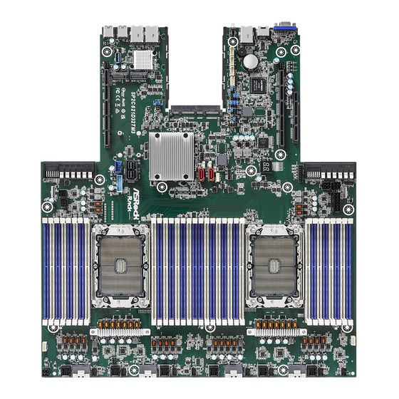
Page 15: Motherboard Layout
SP2C621D32TM3 1.4 Motherboard Layout 47.9cm (18.9in) PANEL1 CPU2_HSBP1 AUX_PANEL1 DDR4_J1 DDR4_J2 GPU_PWR3 HSBP_PWR1 FAN8_1 DDR4_I1 DDR4_I2 DDR4_L1 FAN6_1 GPU_PWR2 DDR4_L2 DDR4_K1 FAN6 DDR4_K2 SLIM4 FNRT_VGA1 PCIE3 VGA1 PCIE_PWR2 PCIE2 CPU2 FAN5_1 Dr. Debug COM1 FAN5 ASPEED 2500 ROM2 BAT1 PMBUS_SEL_ALT1... - Page 16 Description PCIE Power Connector (PCIE_PWR2) PCIE 4.0 x32 Slot (PCIE2) PCIE 4.0 x16 Slot (PCIE3) Front VGA Header (FRONT_VGA1) GPU Power Connector (GPU_PWR2) GPU Power Connector (GPU_PWR3) Power Supply Unit Connector (PSU_CON1) System Panel Header (PANEL1) Auxiliary Panel Header (AUX_PANEL1) HDD Backplane Power Connector (HSBP_PWR1) Backplane PCI Express Hot-Plug Connector (CPU2_HSBP1) 2 x 288-pin DDR4 DIMM Slots (DDR4_I1, DDR4_J1)*...
- Page 17 SP2C621D32TM3 No. Description 2 x 288-pin DDR4 DIMM Slots (DDR4_E2, DDR4_F2)* Slimline x8 Connector (SLIM2) PWM Configuration Header (PWM_CFG1) System Fan Connector (FAN2_1) (for 1U system) System Fan Connector (FAN2) (for 2U system) CPU VSENSE Header (CPU_VSENSE) LGA 4189 CPU Socket (CPU1)
- Page 18 No. Description SATA SGPIO Connector (SSATA_SGPIO1) ESPI Flash Sharing Jumper (ESPI_SHARE) OCP 3.0 Gen4 x16 Mezzanine Card Slot (OCP3) SATA DOM Connector (SSATA0) BIOS Swap Override Header (ESPI_MODE1) ESPI/LPC Selection Jumper (ESPI_LPC_SEL1) ME Recovery Jumper (ME_RECOVERY1) BIOS Recovery Jumper (BIOS_RECOVERY1) Password Reset Jumper (PASSWORD_CLEAR) PMBUS Mode Jumper (PMBUS_SEL_DAT1) PMBUS Mode Jumper (PMBUS_SEL_CLK1)
-
Page 19: Onboard Led Indicators
SP2C621D32TM3 1.5 Onboard LED Indicators Dr. Debug DDR4_O2 DDR4_O2 DDR4_P2 DDR4_P1 DDR4_M2 DDR4_M1 DDR4_N2 DDR4_N1 DDR4_B1 DDR4_B2 DDR4_A1 DDR4_A2 DDR4_D1 DDR4_D2 DDR4_C1 DDR4_C2... - Page 20 Item Status Description BLED Green BMC heartbeat LED LED_CATERR1 CPU CATERR error HDD_LED Green HDD activity LED SYS_FAN_LED6 FAN6_1 failed SYS_FAN_LED5 FAN5_1failed SYS_FAN_LED4 FAN4_1 failed SYS_FAN_LED3 FAN3_1 failed SYS_FAN_LED2 FAN2_1 failed SYS_FAN_LED1 FAN1_1 failed SB_PWR1 Green STB PWR ready...
-
Page 21: I/O Panel
SP2C621D32TM3 1.6 I/O Panel No. Description No. Description VGA Header (VGA1) 1G LAN RJ-45 Port (LAN1)** Serial Port (RJ45) (COM1) 1G LAN RJ-45 Port (LAN2)** IPMI LAN Header (IPMI_LAN1)* USB 3.2 Gen1 Port (USB3_2) UID Switch (UID) USB 3.2 Gen1 Port (USB3_1) LAN Port LED Indications *There are two LED next to the LAN port. - Page 22 *There are two LED next to the LAN port. Please refer to the table below for the LAN port LED indications. ACT/LINK LED SPEED LED LAN Port 1G LAN Port (LAN1, LAN2) LED Indications Activity / Link LED Speed LED Status Description Status...
-
Page 23: Block Diagram
SP2C621D32TM3 1.7 Block Diagram... -
Page 24: Chapter 2 Installation
Chapter 2 Installation This is a T-Shape Proprietary form factor (17” x 19”, 43.18 cm x 48.26 cm) motherboard. Before you install the motherboard, study the configuration of your chassis to ensure that the motherboard fits into it. Make sure to unplug the power cord before installing or removing the motherboard. Failure to do so may cause physical injuries to you and damages to motherboard components. -
Page 25: Installing The Cpu And Heatsink
SP2C621D32TM3 2.3 Installing the CPU and Heatsink 1. Before you insert the CPU into the socket, please check if the PnP cap is on the socket, if the CPU surface is unclean, or if there are any bent pins in the socket. Do not force to insert the CPU into the socket if above situation is found. - Page 26 1. Before you installed the heatsink, you need to spray thermal interface material between the CPU and the heatsink to improve heat dissipation. 2. Illustration in this documentation are examples only. Heatsink or fan cooler type may differ. CPU Carrier...
- Page 27 SP2C621D32TM3...
- Page 28 CPU Carrier...
- Page 29 SP2C621D32TM3 Heatsink CPU Carrier Socket...
-
Page 31: Installation Of Memory Modules (Dimm)
SP2C621D32TM3 2.4 Installation of Memory Modules (DIMM) This motherboard provides thirty-two 288-pin DDR4 (Double Data Rate 4) DIMM slots in two groups, and supports Eight Channel Memory Technology. CPU1 CPU2 DDR4_A1, B1, C1, D1, E1, F1, G1 H1 DDR4_I2, J2, K2, L2, M1, N1, O1, P1... -
Page 32: Dimm Population For Ddr4
2.4.1 DIMM Population for DDR4 The following is the recommended memory population for installing all volatile DDR4 memory modules, without mixing any Intel Persistent Memory 200 series (BPS). Recommended Memory Configurations 1 CPU Configurations (DDR4) DIMM(S) CPU1 The symbol # indicates the slot is populated. - Page 33 SP2C621D32TM3 2 CPU Configurations (DDR4) DIMM(S) CPU1...
- Page 34 DIMM(S) CPU2...
-
Page 35: Dimm Population For Ddr4 And Bps
SP2C621D32TM3 2.4.2 DIMM Population for DDR4 and BPS The following is the recommended memory population for installing Intel Persistent Memory 200 series (BPS) memory modules with DDR4 DIMMs: 1 CPU Configuration (DDR4+BPS) CPU1 DDR4 4 DDR4 DDR4 DDR4 DDR4 DDR4... - Page 36 2 CPU Configuration (DDR4+BPS) CPU1 DDR4 8 DDR4 DDR4 DDR4 DDR4 DDR4 8 BPS 12 DDR4 DDR4 DDR4 DDR4 DDR4 DDR4 DDR4 2 BPS CPU2 DDR4 8 DDR4 DDR4 DDR4 DDR4 DDR4 8 BPS 12 DDR4 DDR4 DDR4 DDR4 DDR4 DDR4 DDR4 2 BPS...
- Page 37 SP2C621D32TM3...
-
Page 38: Expansion Slots (Pci And Pci Express Slots)
2.5 Expansion Slots (PCI and PCI Express Slots) There are 3 PCI Express slots on this motherboard. PCIE slot: PCIE1 (PCIE 4.0 x32 slot, from CPU1) is used for PCI Express x32 lane width cards. PCIE2 (PCIE 4.0 x32 slot, from CPU2) is used for PCI Express x32 lane width cards. PCIE3 (PCIE 4.0 x16 slot, from CPU2) is used for PCI Express x16 lane width cards. -
Page 39: Jumper Setup
SP2C621D32TM3 2.6 Jumper Setup The illustration shows how jumpers are setup. When the jumper cap is placed on the pins, the jumper is “Short”. If no jumper cap is placed on the pins, the jumper is “Open”. The illustration shows a 3-pin jumper whose pin1 and pin2 are “Short” when a jumper cap is placed on these 2 pins. - Page 40 ESPI/LPC Selection Jumper (3-pin ESPI_LPC_SEL1) (see p.7, No. 75) ESPI LPC (Default) ESPI Flash Sharing Jumper (3-pin ESPI_SHARE) (see p.7, No. 71) Master ESPI Flash Sharing Slave ESPI Flash Sharing (Default) QAT Mode Jumper (3-pin QAT_SEL) (see p.7, No. 87) QAT Asymmetric (Default) QAT Symmetric NCSI Mode Jumper...
-
Page 41: Onboard Headers And Connectors
SP2C621D32TM3 2.7 Onboard Headers and Connectors Onboard headers and connectors are NOT jumpers. Do NOT place jumper caps over these headers and connectors. Placing jumper caps over the headers and connectors will cause permanent damage to the motherboard. System Panel Header... - Page 42 Auxiliary Panel Header This header supports multiple (18-pin AUX_PANEL1) functions on the front panel, (see p.7, No. 9) including front panel SMB, internet status indicator. AUX_PANEL1 +3VSB +3VSB LOCATORLED+ PLED- LOCATORLED- System Fault LED- HDLED- PWRBTN# RESET# SMB_DATA SMB_CLK LOCATORBTN# Non Maskable Interrupt Please connect a NMI device Button Header...
- Page 43 SP2C621D32TM3 Front USB 3.2 Gen1 Besides four default USB 3.2 Header Gen1 ports on the I/O panel, (19-pin USB3_3) there are two USB 3.2 Gen1 (see p.7, No. 54) headers on this motherboard. Each USB 3.2 Gen1 header USB3_3 can support two USB 3.2 Gen1 ports.
- Page 44 BMC SMB Headers These headers are used for the (5-pin BMC_SMB1) SM BUS devices. BMC_SMB_PRESENT_1_N (see p.7, No. 81) Power (5-pin BMC_SMB2) BMC_SMBCLK (see p.7, No. 82) BMC_SMBDATA (5-pin BMC_SMB3) (see p.7, No. 83) SPI TPM Header This connector supports SPI (13-pin SPI_TPM_J1) Trusted Platform Module SPI_DQ3...
- Page 45 SP2C621D32TM3 System Fan Connectors Please connect fan cables to the 12V(FAN_VOLTAGE) FAN1 SENSOR fan connectors and match the (for 1U system) FAN2 SENSOR (6-pin FAN1_1) black wire to the ground pin. (see p.7, No. 43) All fans support Fan Control.
- Page 46 Backplane Power Please connect a 12-pin power +12V Connector cable to this connector to (12-pin HSBP_PWR1) connect a HDD. (see p.7, No. 10) (4-pin HSBP_PWR2) (see p.7, No. 50) IPMB_SDA Intelligent Platform This 4-pin connector is used IPMB_SCL Management Bus header to provide a cabled baseboard (4-pin IPMB1) or front panel connection for...
- Page 47 SP2C621D32TM3 USB 3.2 Gen1 Connector (USB3_6) (see p.7, No. 63) USB 3.2 Gen1 Header Besides four default USB 3.2 IntA_PA_D+ IntA_PA_D- (19-pin USB3_5_6) Gen1 ports on the I/O panel, IntA_PA_SSTX+ (see p.7, No. 78) there is one USB 3.2 Gen1 IntA_PA_SSTX- header on this motherboard.
- Page 48 Serial ATA3 Connectors These two SATA3 connectors SSATA0 (SSATA0) support SATA data cables for (see p.7, No. 73) internal storage devices with SSATA1 (SSATA1) up to 6.0 Gb/s data transfer (see p.7, No. 67) rate. Serial ATA3 DOM The SATA3 DOM connectors SSATA0 Connectors support both a SATA DOM...
- Page 49 SP2C621D32TM3 Virtual RAID On CPU This connector supports Intel® Header Virtual RAID on CPU and +3VSB (4-pin RAID_1) NVME/AHCI RAID on CPU (see p.7, No. 90) VROC RAID KEY PCIE. With the introduction of the Intel VROC product, there are three modes of operation:...
- Page 50 Slimline SAS Connectors These connectors are used for Right-Angle: the NVME PCIE devices. (SLIM1) (see p.7, No. 45) (SLIM2) (see p.7, No. 37) (SLIM3) (see p.7, No. 25) (SLIM4) (see p.7, No. 19) 77 79 78 80...
- Page 51 SP2C621D32TM3 80-pin Defeinition Pin Defeinition GND_1 GND_12 RX_0+ TX_0+ RX_0- TX_0- GND_2 GND_13 RX_1+ TX_1+ RX_1- TX_1- GND_3 GND_14 SIDEBAND_7A SIDEBAND_0A SIDEBAND_4A SIDEBAND_1A SIDEBAND_A+ SIDEBAND_5A SIDEBAND_A- SIDEBAND_6A GND_4 GND_15 RX_2+ TX_2+ RX_2- TX_2- GND_5 GND_16 RX_3+ TX_3+ RX_3- TX_3- GND_6...
-
Page 52: Dr. Debug
2.8 Dr. Debug Dr. Debug is used to provide code information, which makes troubleshooting even easier. Please see the diagrams below for reading the Dr. Debug codes. Code Description 0x10 PEI_CORE_STARTED 0x11 PEI_CAR_CPU_INIT 0x15 PEI_CAR_NB_INIT 0x19 PEI_CAR_SB_INIT 0x31 PEI_MEMORY_INSTALLED 0x32 PEI_CPU_INIT 0x33 PEI_CPU_CACHE_INIT... - Page 53 SP2C621D32TM3 0x63 DXE_CPU_INIT 0x68 DXE_NB_HB_INIT 0x69 DXE_NB_INIT 0x6A DXE_NB_SMM_INIT 0x70 DXE_SB_INIT 0x71 DXE_SB_SMM_INIT 0x72 DXE_SB_DEVICES_INIT 0x78 DXE_ACPI_INIT 0x79 DXE_CSM_INIT 0x90 DXE_BDS_STARTED 0x91 DXE_BDS_CONNECT_DRIVERS 0x92 DXE_PCI_BUS_BEGIN 0x93 DXE_PCI_BUS_HPC_INIT 0x94 DXE_PCI_BUS_ENUM 0x95 DXE_PCI_BUS_REQUEST_RESOURCES 0x96 DXE_PCI_BUS_ASSIGN_RESOURCES 0x97 DXE_CON_OUT_CONNECT 0x98 DXE_CON_IN_CONNECT...
- Page 54 0x99 DXE_SIO_INIT 0x9A DXE_USB_BEGIN 0x9B DXE_USB_RESET 0x9C DXE_USB_DETECT 0x9D DXE_USB_ENABLE 0xA0 DXE_IDE_BEGIN 0xA1 DXE_IDE_RESET 0xA2 DXE_IDE_DETECT 0xA3 DXE_IDE_ENABLE 0xA4 DXE_SCSI_BEGIN 0xA5 DXE_SCSI_RESET 0xA6 DXE_SCSI_DETECT 0xA7 DXE_SCSI_ENABLE 0xA8 DXE_SETUP_VERIFYING_PASSWORD 0xA9 DXE_SETUP_START 0xAB DXE_SETUP_INPUT_WAIT 0xAD DXE_READY_TO_BOOT 0xAE DXE_LEGACY_BOOT...
- Page 55 SP2C621D32TM3 0xAF DXE_EXIT_BOOT_SERVICES 0xB0 RT_SET_VIRTUAL_ADDRESS_MAP_BEGIN 0xB1 RT_SET_VIRTUAL_ADDRESS_MAP_END 0xB2 DXE_LEGACY_OPROM_INIT 0xB3 DXE_RESET_SYSTEM 0xB4 DXE_USB_HOTPLUG 0xB5 DXE_PCI_BUS_HOTPLUG 0xB6 DXE_NVRAM_CLEANUP 0xB7 DXE_CONFIGURATION_RESET 0xF0 PEI_RECOVERY_AUTO 0xF1 PEI_RECOVERY_USER 0xF2 PEI_RECOVERY_STARTED 0xF3 PEI_RECOVERY_CAPSULE_FOUND 0xF4 PEI_RECOVERY_CAPSULE_LOADED 0xE0 PEI_S3_STARTED 0xE1 PEI_S3_BOOT_SCRIPT 0xE2 PEI_S3_VIDEO_REPOST...
- Page 56 0xE3 PEI_S3_OS_WAKE 0x50 PEI_MEMORY_INVALID_TYPE 0x53 PEI_MEMORY_NOT_DETECTED 0x55 PEI_MEMORY_NOT_INSTALLED 0x57 PEI_CPU_MISMATCH 0x58 PEI_CPU_SELF_TEST_FAILED 0x59 PEI_CPU_NO_MICROCODE 0x5A PEI_CPU_ERROR 0x5B PEI_RESET_NOT_AVAILABLE 0xD0 DXE_CPU_ERROR 0xD1 DXE_NB_ERROR 0xD2 DXE_SB_ERROR 0xD3 DXE_ARCH_PROTOCOL_NOT_AVAILABLE 0xD4 DXE_PCI_BUS_OUT_OF_RESOURCES 0xD5 DXE_LEGACY_OPROM_NO_SPACE 0xD6 DXE_NO_CON_OUT 0xD7 DXE_NO_CON_IN...
- Page 57 SP2C621D32TM3 0xD8 DXE_INVALID_PASSWORD 0xD9 DXE_BOOT_OPTION_LOAD_ERROR 0xDA DXE_BOOT_OPTION_FAILED 0xDB DXE_FLASH_UPDATE_FAILED 0xDC DXE_RESET_NOT_AVAILABLE 0xE8 PEI_MEMORY_S3_RESUME_FAILED 0xE9 PEI_S3_RESUME_PPI_NOT_FOUND 0xEA PEI_S3_BOOT_SCRIPT_ERROR 0xEB PEI_S3_OS_WAKE_ERROR...
-
Page 58: Identification Purpose Led/Switch
2.9 Identification purpose LED/Switch With the UID button, You are able to locate the server you’re working on from behind a rack of servers. Unit Identification When the UID button on the purpose LED/Switch front or rear panel is pressed, (UID1) the front/rear UID blue LED indicator will be truned on. -
Page 59: Dual Lan And Teaming Operation Guide
SP2C621D32TM3 2.10 Dual LAN and Teaming Operation Guide Dual LAN with Teaming enabled on this motherboard allows two single connections to act as one single connection(s) for twice the transmission bandwidth, making data transmission more effective and improving the quality of transmission of distant images. -
Page 60: Ssd Module Installation Guide
2.11 M.2 SSD Module Installation Guide The Ultra M.2 Socket (M2_1/M2_2, Key M) supports either a M.2 SATA3 6.0 Gb/s module or a M.2 PCI Express module up to Gen3 x4 (32Gb/s). Installing the M.2 SSD Module Step 1 Prepare a M.2 SSD module and the screw. - Page 61 SP2C621D32TM3 Step 3 Move the standoff based on the module type and length. Skip Step 3 and 4 and go straight to Step 5 if you are going to use the default nut. Otherwise, release the standoff by hand. Step 4 Peel off the yellow protective film on the nut to be used.
-
Page 62: Chapter 3 Uefi Setup Utility
Chapter 3 UEFI Setup Utility 3.1 Introduction This section explains how to use the UEFI SETUP UTILITY to configure your system. The UEFI chip on the motherboard stores the UEFI SETUP UTILITY. You may run the UEFI SETUP UTILITY when you start up the computer. Please press <F2> or <Del> during the Power-On-Self-Test (POST) to enter the UEFI SETUP UTILITY;... -
Page 63: Navigation Keys
SP2C621D32TM3 3.1.2 Navigation Keys Please check the following table for the function description of each navigation key. Navigation Key(s) Function Description Moves cursor left or right to select Screens Moves cursor up or down to select items + / - To change option for the selected items <Tab>... -
Page 64: Main Screen
3.2 Main Screen Once you enter the UEFI SETUP UTILITY, the Main screen will appear and display the system overview. The Main screen provides system overview information and allows you to set the system time and date. -
Page 65: Advanced Screen
SP2C621D32TM3 3.3 Advanced Screen In this section, you may set the configurations for the following items: CPU Configuration, DRAM Configuration, Chipset Configuration, Storage Configuration, NVMe Configura- tion, ACPI Configuration, USB Configuration, Super IO Configuration, Serial Port Con- sole Redirection, H/W Monitor, Runtime Error Logging, Network Stack Configuration, Intel SPS Configuration, Intel VMD Technology, Tls Auth Configuration and Instant Flash. -
Page 66: Cpu Configuration
3.3.1 CPU Configuration Intel SpeedStep Technology Intel SpeedStep technology allows processors to switch between multiple frequencies and voltage points for better power saving and heat dissipation. CPU turbo ratio can be fixed when Intel SpeedStep Technology set Disabled and Intel Turbo Boost Technology set En- abled. -
Page 67: Intel Virtualization Technology
SP2C621D32TM3 Short Duration Power Limit Configure Package Power Limit 2 in watts. When the limit is exceeded, the CPU ratio will be lowered immediately. A lower limit can protect the CPU and save power, while a higher limit may improve performance. - Page 68 Enhanced Halt State(C1E) Enable Enhanced Halt State (C1E) for lower power consumption. Hardware P-States Disable: Hardware chooses a P-state based on OS Request (Legacy P-States) Native Mode: Hardware chooses a P-state based on OS guidance Out of Band Mode: Hardware autonomously chooses a P-state (no OS guidance) AES-NI Use this item to enable or disable AES-NI support.
-
Page 69: Dram Configuration
SP2C621D32TM3 3.3.2 DRAM Configuration Enforce POR Enforce POR - Enforces Plan Of Record restrictions for DDR4 frequency and voltage programming. Disable - Disables this feature. DRAM Frequency If [Auto] is selected, the motherboard will detect the memory module(s) inserted and assign the appropriate frequency automatically. -
Page 70: Patrol Scrub
ADDDC Sparing Enable or disable ADDDC Sparing. Patrol Scrub Patrol Scrub is a background activity initiated by the processor to seek out and fix memory errors. The default value is [Enabled]. Data Scrambling for DDR4 Enable - Enables data scrambling for DDR4. Disable - Disables this feature. -
Page 71: Chipset Configuration
SP2C621D32TM3 3.3.3 Chipset Configuration MMCFG Base Use this item to select MMCFG Base. MMIO High Base Use this item to select MMIO High Base. MMIO High Granularity Size Use this item to select the allocation size used to assign mmioh resources. Total mmioh space can be up to 32x granularity. -
Page 72: Onboard Vga
Onboard VGA Use this to enable or disable the Onboard VGA function. The default value is [Auto]. *This item is not available when the Primary Graphic Adapter is set to [Onboard VGA]. Onboard VGA Output Select the onboard VGA output to rear side or front side. VT-d Intel(R) Virtualization Technology for Directed I/O helps the virtual machine monitor better utilize hardware by improving application compatibility and reliability, and provid-... -
Page 73: Sr-Iov Support
SP2C621D32TM3 SLIM2/SLIM1 Link Speed This allows user to select PCIE Link Speed. The default value is [Auto]. SLIM4/SLIM3 Link Width This allows user to select SLIM4/SLIM3 Link Width. The default value is [x4x4/x4x4]. SLIM4/SLIM3 Link Speed This allows user to select PCIE Link Speed. The default value is [Auto]. -
Page 74: Storage Configuration
3.3.4 Storage Configuration SATA Controller Use this item to enable or disable SATA Controllers. SATA Mode Selection Identify the SATA port is connected to Solid State Drive or Hard Disk Drive. Press <Ctrl+I> to enter RAID ROM during UEFI POST process. SATA ALPM Use this item to enable or disable Support Aggressive Link Power Management. -
Page 75: Nvme Configuration
SP2C621D32TM3 3.3.5 NVMe Configuration If there is a NVMe device installed on the motherboard, the NVMe Configuration page will display the relevant information of the NVMe device you are using. Please note that the information and items shown here may vary depending on the NVMe device you use. -
Page 76: Acpi Configuration
3.3.6 ACPI Configuration PCIE Devices Power On Allow the system to be waked up by a PCIE device and enable wake on LAN. Ring-In Power On Use this item to enable or disable Ring-In signals to turn on the system from the power- soft-off mode. -
Page 77: Usb Configuration
SP2C621D32TM3 3.3.7 USB Configuration Legacy USB Support Enable or disable Legacy OS Support for USB 2.0 devices. If you encounter USB compatibility issues it is recommended to disable legacy USB support. Select UEFI Setup Only to support USB devices under the UEFI setup and Windows/Linux... -
Page 78: Super Io Configuration
3.3.8 Super IO Configuration Serial Port 1 Configuration Use this item to set parameters of SOL. Serial Port Use this item to enable or disable Serial Port (COM). Change Settings Use this item to select an optimal setting for Super IO device. SOL Configuration Use this item to set parameters of SOL. -
Page 79: Serial Port Console Redirection
SP2C621D32TM3 3.3.9 Serial Port Console Redirection COM1/SOL Console Redirection Use this option to enable or disable Console Redirection. If this item is set to Enabled, you can select a COM Port to be used for Console Redirection. Console Redirection Settings Use this option to configure Console Redirection Settings, and specify how your computer and the host computer to which you are connected exchange information. -
Page 80: Flow Control
Bits Per Second Use this item to select the serial port transmission speed. The speed used in the host computer and the client computer must be the same. Long or noisy lines may require lower transmission speed. The options include [9600], [19200], [38400], [57600] and [115200]. Data Bits Use this item to set the data transmission size. -
Page 81: Serial Port For Out-Of-Band Management/Windows Emergency Management Services (Ems)
SP2C621D32TM3 Redirection COM Port Use this item to select a COM port to display redirection of Legacy OS and Legacy OPROM Messages. Resolution On Legacy OS, the Number of Rows and Columns supported redirection. Redirection After POST If the [Bootloader] is selected, legacy console redirection is disabled before booting to legacy OS. - Page 82 Data Bits EMS Parity EMS Stop Bits EMS...
-
Page 83: H/W Monitor
SP2C621D32TM3 3.3.10 H/W Monitor In this section, it allows you to monitor the status of the hardware on your system, includ- ing the parameters of the CPU temperature, motherboard temperature, CPU fan speed, chassis fan speed, and the critical voltage. -
Page 84: Runtime Error Logging
3.3.11 Runtime Error Logging WHEA Support Use this item to enable or disable Windows Hardware Error Architecture. System Error Use this item to enable or disable System Error feature. Set it to [Enabled] to configure Memory Error and PCIE Error log features. S/W Error Injection Support When it is set to [Enabled], S/W Error Injection is supported by unlocking MSR Ox790. - Page 85 SP2C621D32TM3 PCIE Uncorrected Error Enable Use this item to enable or disable PCIe Uncorrectable errors. PCIE Fatal Error Enable Use this item to enable or disable PCIe Ftal errors.
-
Page 86: Network Stack Configuration
3.3.12 Network Stack Configuration Network Stack Enable UEFI network stack can prevents user from performing single-user network boots and network installation. If disabled, the host does not use the network interface. IPv4 PXE Support Enable or disable IPv4 PXE boot support. If disabled, IPv4 PXE boot support will not be available. -
Page 87: Media Detect Count
SP2C621D32TM3 PXE Boot Wait Time Specifies the wait time in seconds and press the ESC key to abort the PXE boot. Use either +/- or numeric keys to set the value. Media detect count Number of times the presence of media will be checked. Use either +/- or numeric keys to... -
Page 88: Intel Sps Configuration
3.3.13 Intel SPS Configuration SPS screen displays the Intel SPS Configuration information, such as Operational Firmware Version and Firmware State. -
Page 89: Intel® Vmd Technology
SP2C621D32TM3 3.3.14 Intel® VMD technology ® Press <Enter> to bring up the Intel VMD for Volume Management Device Configuration menu. ® Intel VMD for Volume Management Device on Socket 0 VMD Config for IOU 1 (PCIE1) Enable/Disable VMD Use this item to enable or disable Intel(R) Volume Management Device Technology in this Stack. - Page 90 VMD port D Use this item to enable or disable Intel(R) Volume Management Device Technology on specific root port. Hot Plug Capable Use this item to enable or disable Hot Plug for PCIe Root Ports. VMD Config for IOU 3 (PCIE1) Enable/Disable VMD Use this item to enable or disable Intel(R) Volume Management Device Technology in this Stack.
- Page 91 SP2C621D32TM3 VMD port B Use this item to enable or disable Intel(R) Volume Management Device Technology on specific root port. VMD port C Use this item to enable or disable Intel(R) Volume Management Device Technology on specific root port. VMD port D Use this item to enable or disable Intel(R) Volume Management Device Technology on specific root port.
- Page 92 VMD Config for IOU 1 (PCIE2) Enable/Disable VMD Use this item to enable or disable Intel(R) Volume Management Device Technology in this Stack. When [Enabled], users are allowed to configure the options below. VMD port A Use this item to enable or disable Intel(R) Volume Management Device Technology on specific root port.
- Page 93 SP2C621D32TM3 VMD port C Use this item to enable or disable Intel(R) Volume Management Device Technology on specific root port. VMD port D Use this item to enable or disable Intel(R) Volume Management Device Technology on specific root port. Hot Plug Capable Use this item to enable or disable Hot Plug for PCIe Root Ports.
-
Page 94: Tls Auth Configuratio
3.3.15 Tls Auth Configuratio Server CA Configuration Press <Enter> to configure Server CA. Client Cert Configuration Enroll Cert Press <Enter> to enroll cert. Delete Cert Press <Enter> to delete cert. -
Page 95: Instant Flash
SP2C621D32TM3 3.3.15 Instant Flash Instant Flash is a UEFI flash utility embedded in Flash ROM. This convenient UEFI update tool allows you to update system UEFI without entering operating systems first like MS- ® DOS or Windows . Just save the new UEFI file to your USB flash drive, floppy disk or hard drive and launch this tool, then you can update your UEFI only in a few clicks without pre- paring an additional floppy diskette or other complicated flash utility. -
Page 96: Security
3.4 Security In this section, you may set or change the supervisor/user password for the system. For the user password, you may also clear it. Supervisor Password Set or change the password for the administrator account. Only the administrator has authority to change the settings in the UEFI Setup Utility. Leave it blank and press enter to remove the password. -
Page 97: Key Management
SP2C621D32TM3 3.4.1 Key Management In this section, expert users can modify Secure Boot Policy variables without full authenti- cation. Factory Key Provision Install factory default Secure Boot keys after the platform reset and while the System is in Setup mode. -
Page 98: Platform Key(Pk)
Remove 'UEFI CA' from DB Device Guard ready system must not list ‘Microsoft UEFI CA’ Certificate in Autho- rized Signature database (db). Restore DB Defaults Restore DB variable to factory defaults. Platform Key(PK) Enroll Factory Defaults or load certificates from a file: 1. -
Page 99: Forbidden Signatures
SP2C621D32TM3 1. Public Key Certificate in: a) EFI_SIGNATURE_LIST b) EFI_CERT_X509 (DER) c) EFI_CERT_RSA2048 (bin) d) EFI_CERT_SHAXXX 2. Authenticated UEFI Variable 3. EFI PE/COFF Image(SHA256) Key Source: Default, External, Mixed Forbidden Signatures Enroll Factory Defaults or load certificates from a file: 1. -
Page 100: Osrecovery Signatures
OsRecovery Signatures Enroll Factory Defaults or load certificates from a file: 1. Public Key Certificate in: a) EFI_SIGNATURE_LIST b) EFI_CERT_X509 (DER) c) EFI_CERT_RSA2048 (bin) d) EFI_CERT_SHAXXX 2. Authenticated UEFI Variable 3. EFI PE/COFF Image(SHA256) Key Source: Default, External, Mixed... -
Page 101: Boot Screen
SP2C621D32TM3 3.5 Boot Screen In this section, it will display the available devices on your system for you to configure the boot settings and the boot priority. Boot Option #1 Use this item to set the system boot order. Boot Option Filter This option controls Legacy/UEFI ROMs priority. - Page 102 Full Screen Logo Use this item to enable or disable OEM Logo. The default value is [Enabled]. AddOn ROM Display Use this option to adjust AddOn ROM Display. If you enable the option “Full Screen Logo” but you want to see the AddOn ROM information when the system boots, please select [Enabled].
-
Page 103: Csm Parameters
SP2C621D32TM3 3.5.1 CSM Parameters Enable to launch the Compatibility Support Module. Please do not disable unless you’re running a WHCK test. If you are using Windows Server 2012 R2 or later ver- sions 64-bit UEFI and all of your devices support UEFI, you may also disable CSM for faster boot speed. - Page 104 PCIE1 Slot OpROM Use this item to select slot storage and Network Option ROM policy. In Auto option, the default is Disabled with NVMe device, but it is Legacy with other devices. (This item can't select Video Option ROM policy.) SLIM2 Slot OpROM Use this item to select slot storage and Network Option ROM policy.
- Page 105 SP2C621D32TM3 M2_2 Slot OpROM Use this item to select slot storage and Network Option ROM policy. In Auto option, the default is Disabled with NVMe device, but it is Legacy with other devices. (This item can't select Video Option ROM policy.)
-
Page 106: Server Mgmt
3.6 Server Mgmt Wait For BMC Wait For BMC response for specified time out. BMC starts at the same time when BIOS starts during AC power ON. It takes around 90 seconds to initialize Host to BMC interfaces. -
Page 107: Bmc Network Configuration
SP2C621D32TM3 3.6.1 BMC Network Configuration BMC Out of Band Access Enabled/Disabled BMC Out of band Access. Lan Channel (Failover) Manual Setting IPMI LAN If [No] is selected, the IP address is assigned by DHCP. If you prefer using a static IP address, toggle to [Yes], and the changes take effect after the system reboots. -
Page 108: Ipv6 Support
The default login information for the IPMI web interface is: Username: admin Password: admin For more instructions on how to set up remote control environment and use the IPMI man- agement platform, please refer to the IPMI Configuration User Guide or go to the Support website at: http://www.asrockrack.com/support/ipmi.asp VLAN Enabled/Disabled Virtual Local Area Network. -
Page 109: System Event Log
SP2C621D32TM3 3.6.2 System Event Log SEL Components Change this to enable ro disable all features of System Event Logging during boot. Erase SEL Use this to choose options for earsing SEL. When SEL is Full Use this to choose options for reactions to a full SEL. -
Page 110: View System Event Log
3.6.3 View System Event Log This page display the information of the system event log. -
Page 111: Bmc Tools
SP2C621D32TM3 3.6.4 BMC Tools Load BMC Default Settings Use this item to Load BMC Default Settings KCS Control Select this KCS interface state after POST end. If [Enabled] us selected, the BMC will remain KCS interface after POST stage. If [Disabled] is selected, the BMC will disable KCS interface after POST stage All values changed here do not take effect until computer is restarted. -
Page 112: Event Logs
3.7 Event Logs Change Smbios Event Log Settings This allows you to configure the Smbios Event Log Settings. When entering the item, you will see the followings: Smbios Event Log Use this item to enable or disable all features of the SMBIOS Event Logging during system boot. - Page 113 SP2C621D32TM3 entries which utilize a multiple-event counter. The value ranges from 0 to 99 minutes. Log EFI Status Code Enable or disable the logging of EFI Status Codes as OEM reserved type E0 (if not already converted to legacy). Convert EFI Status Codes to Standard Smbios Type Enable or disable the converting of EFI Status Codes to Standard Smbios Types (Not all may be translated).
-
Page 114: Exit Screen
3.8 Exit Screen Save Changes and Exit When you select this option, the following message “Save configuration changes and exit setup?” will pop-out. Press <F10> key or select [Yes] to save the changes and exit the UEFI SETUP UTILITY. Discard Changes and Exit When you select this option, the following message “Discard changes and exit setup?”... -
Page 115: Boot Override
SP2C621D32TM3 Boot Override These items displays the available devices. Select an item to start booting from the selected device. -
Page 116: Chapter 4 Software Support
4.3 Contact Information If you need to contact ASRock Rack or want to know more about ASRock Rack, welcome to visit ASRock Rack’s website at http://www.ASRockRack.com; or you may contact your... -
Page 117: Chapter 5 Troubleshooting
SP2C621D32TM3 Chapter 5 Troubleshooting 5.1 Troubleshooting Procedures Follow the procedures below to troubleshoot your system. Always unplug the power cord before adding, removing or changing any hardware com- ponents. Failure to do so may cause physical injuries to you and damages to motherboard components. - Page 118 1. Verify if the battery on the motherboard provides ~3VDC. Install a new battery if it does not. 2. Confirm whether your power supply provides adaquate and stable power. Other problems... 1. Try searching keywords related to your problem on ASRock Rack’s FAQ page: http://www.asrockrack.com/support...
-
Page 119: Technical Support Procedures
SP2C621D32TM3 5.2 Technical Support Procedures If you have tried the troubleshooting procedures mentioned above and the problems are still unsolved, please contact ASRock Rack’s technical support with the following information: 1. Your contact information 2. Model name, BIOS version and problem type. -
Page 120: Contact Information
Contact Information If you need to contact ASRock Rack or want to know more about ASRock Rack, you’re welcome to visit ASRock Rack’s website at http://www.asrockrack.com; or you may contact your dealer for further information. For technical questions, please submit a support request form at https://event.asrockrack.com/tsd.asp...
Need help?
Do you have a question about the SP2C621D32TM3 and is the answer not in the manual?
Questions and answers